
Abstract
This article concerns a hybrid vehicle suspension system that can regenerate energy from vibrations. To further improve the performance of the hybrid vehicle suspension system, the design of the energy-regenerative circuit is investigated. First, the force tests of the linear motor used in the hybrid vehicle suspension were carried out, and the key parameters of the linear motor were obtained. Then, the selection procedures of the protective resistance, inductance, and initial terminal voltage of the super capacitor were discussed. These aforementioned parameters’ values were determined by considering the impact of the hybrid suspension on the dynamic performance indexes and the energy-regenerative efficiency. Simulations showed that, in comparison to the original hybrid suspension system, the designed hybrid suspension effectively improved the energy-regenerative efficiency, and that the dynamic performance indexes of the suspension were synchronously improved. Given the result of the simulation analysis, which were validated by bench tests, it is shown that the optimized energy-regenerative circuit presents an enhanced regeneration efficiency, with an improvement of nearly 13% compared to the original suspension system.
Introduction
The vehicle suspension system is the fundamental device for improving ride comfort and handling stability.1–4 Recently, researchers found that the energy of the suspension vibration can be regenerated by means of magnetic suspension5–11 and piezoelectric suspension.12–16 In Segal and Lu, 17 the influence of suspension damping, tires, and road surface roughness on the vehicle running resistance was analyzed, and it was noted that, when the vehicle drove at a speed of 48 km/h, the damper dissipated approximately 200 W of energy. Hsu 18 deeply studied the active suspension based on the Linear-Quadratic-Gaussian (LQG) control strategy, and it was found that, when the vehicle was driving at a high speed of 96 km/h, the vibration energy can be regenerated by 400 J. Yu et al. 19 analyzed the feasibility of the active energy-regenerative suspension, and the simulation results showed that, when the vehicle drove at 20 m/s on a C level road for 20 s, the energy dissipated by the passive suspension was 651 kJ. However, the feed-in energy cannot reflect the energy recovery capacity of the energy-regenerative suspension and the energy-regenerative efficiency should be used to reflect the energy-regenerative capacity. In Zhang et al., 20 a novel regenerative shock absorber was designed and fabricated, and the double speed regenerative shock absorber utilizing the rack and pinion mechanism was applied to increase the magnet speed. The results showed that the proposed design can increase the output power by four times compared to the baseline design under the sinusoidal and random road input.
The hybrid suspension represents a suspension that can effectively suppress the vibration and regenerate the vibration energy at the same time. An energy-harvesting vehicle damper was proposed in Xie et al. 21 to replace traditional hydraulic dampers, and it consists of multiple generators that are independently controlled by switches. Simulations and experimental tests were conducted and indicated that changing the number of switched-on generators can obviously tune the damping coefficient of the damper and simultaneously produce considerable electricity. In Shi et al., 22 a new type of semi-active energy-regenerative suspension system was proposed to recover suspension vibration energy, as well as reduce the suspension cost and demands for the motor rated capacity. The results showed that the semi-active energy-regenerative suspension can improve vehicle ride comfort with the controllable damping characteristics of the linear motor. Meanwhile, it also ensured energy regeneration. Moreover, a method to analyze the balance between regenerative energy and consumed energy based on a single electric actuator was proposed in Nakano et al., 23 and the regenerative control of an electro dynamic actuator was investigated in Okada and Harada. 24 However, the energy-regenerative circuit was not analyzed and discussed in detail to further improve the performance of the hybrid vehicle suspension.
This article will focus on the study of the design of the energy-regenerative circuit in the hybrid vehicle suspension. The structure of the article is arranged as follows. In the “Hybrid vehicle suspension system” section, the hybrid vehicle suspension and the energy-regenerative circuit are introduced and the dynamic model is established. Then, the force tests of the linear motor is presented in the “Bench test of the linear motor” section to obtain the parameters of the device. In the “Design of the energy-regenerative circuit” section, the three key parameters, namely, the protective resistance, the inductance, and the initial terminal voltage of the super capacitor, and their impacts on the dynamic indexes of the suspension and the energy regenerated efficiency are discussed and investigated in detail. Simulations are carried out in the “Simulation analysis” section to show the effectiveness of the hybrid vehicle suspension, and bench tests are conducted in the section “Experimental study” to validate the advantages of the proposed hybrid vehicle suspension system. Some conclusions are drawn in the “Conclusion” section.
Hybrid vehicle suspension system
Hybrid vehicle suspension model
Taking a quarter car model as an example, the hybrid vehicle suspension system is illustrated in Figure 1.

Hybrid vehicle suspension system.
In Figure 1, mb is the sprung mass, mt is the unsprung mass, ks is the suspension stiffness, cs is the damper, kt is the tire stiffness, and z0, zt, and zb are the vertical displacement of the road input, the unsprung mass, and the sprung mass, respectively. FM is the force of the linear motor device. The dynamic model of the hybrid vehicle suspension on the basis of the quarter car model is depicted in equation (1)

It is seen that the linear motor is parallel to the suspension spring and the damper. The linear motor can not only regenerate the vibration energy by means of the energy-regenerative circuit but also can suppress the vibration when there is current in the external circuit.
Energy-regenerative circuit
The linear motor is connected with the energy-regenerative circuit, which is illustrated in Figure 2.

Basic structure of the energy-regenerative circuit.
In Figure 2, the induced AC is generated by the motion of the linear motor and can be transformed into DC through the bridge rectifier. L is the inductance of the linear motor, and R is the resistor of the linear motor. SC is the super capacitor used to store the vibration energy. In the Boost–Buck convertor, Ldc is the storage inductor, Rv is the protective resistor, and VT1, VT2, and VT3 are the power switches. There are typically two modes of the energy-regenerative circuit by controlling the power switches. When VT1 switch is on, VT3 is off, and VT2 works as a step-up chopper in the boost mode. When VT2 is off, VT1 works as a step-down chopper in the buck mode. In the boost mode and the buck mode, the current in the circuit will be changed because of the variation of the voltage. Thus, the feedback damping force of the hybrid vehicle suspension will also be changed.
Bench test of the linear motor
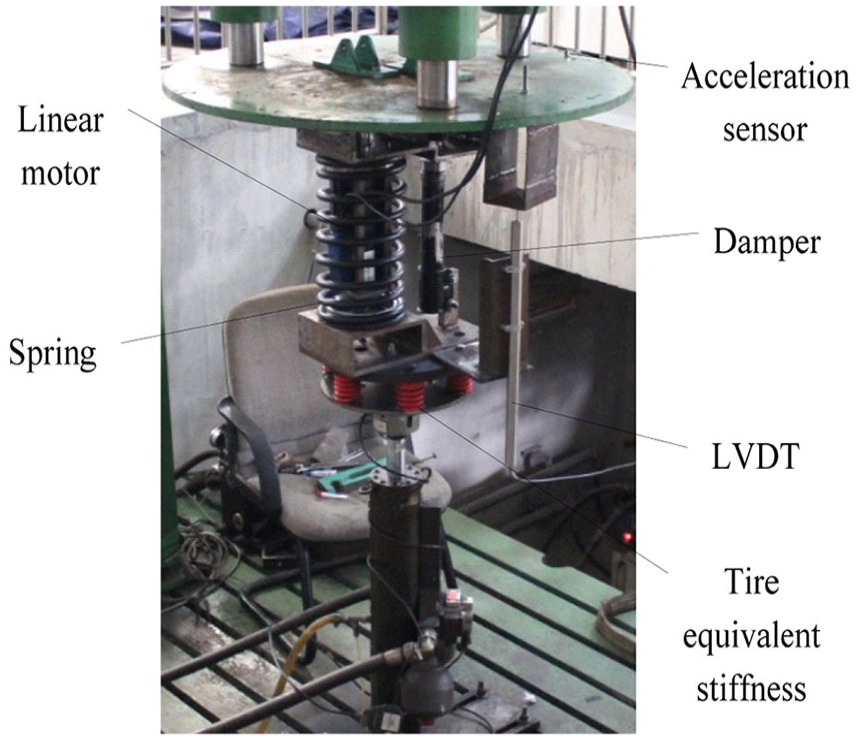
To obtain the detailed parameters of the linear motor, a force test of the linear motor was carried out, and the layout of the bench test is shown in Figure 3.

Force test of the linear motor.
The linear motor was excited by different frequency sine displacements, and the velocity signal, force signal, voltage signal, and current signal were collected by sensors and oscilloscope. The relationships between the speed of the linear motor and the induced voltage are shown in Figure 4, and the relationships between the induced voltage and the output force are shown in Figure 5.
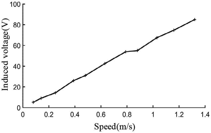
The relationships between the speed of the linear motor and the induced voltage.

Relationships between the induced voltage and the output force.
In terms of the linear motor, the equations are


where U is the voltage of the linear motor, F is the force of the linear motor, ke is the Back-Electronic-Manufacturing-Facility (EMF) coefficient, and kn is the force coefficient of the linear motor. According to equation (2) and Figure 4, ke = 64.4 Vs/m. Figure 5 shows the relationships between the linear motor force and the voltage when there is only a 10 Ω resistor connected in the external circuit. In that case, kn = 78.8 N/A.
Design of the energy-regenerative circuit
Analysis of the resistance
The protective resistance is working in the Buck mode, and the schematic of the working condition is shown in Figure 6. When we do not take the influence of the linear motor inductance L into consideration, according to the Kirchhoff law, the equation is

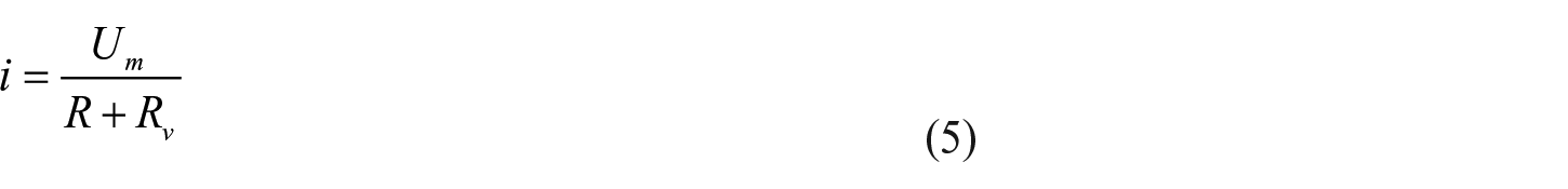
The power of the load resistance Rv can be obtained as follows

Equation (4) is brought into equation (5), yielding

In equation (7), when Rv = R, the power of the protective resistor is the largest, and thus the power of the resistor of the linear motor will be minimized. Therefore, the protective resistor will be set to the same value as the resistor of the linear motor.
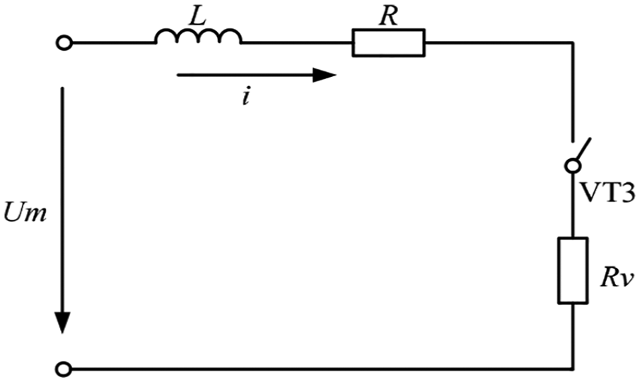
Second stage of the Buck mode.
Analysis of the inductance
An inductor is an electrical element that can convert electrical energy into magnetic energy and store it. The inductor has the following characteristics: when there is no current running through it, it will block the current flowing through it while the circuit is connected, and when the current flows through it, it will try to maintain the same current while the circuit is disconnected. Thus, the inductor has the function of storing temporary energy. When the energy-regenerative circuit works in the Boost mode, the calculation of the inductor can be conducted according to the following formula 6


In equations (8) and (9), Uout is the output terminal voltage of the energy-regenerative circuit, Ts is the switching period, D is the duty ratio of the Metal-Oxide-Semiconductor (MOS) tube, I is the current change value of the flow through the inductor, and fs is the switching frequency.
According to the actual situation and test data, select Uout = 20 V, D = 1/3, and I = 4 A. Because the working noise of the MOS tube in the 9~10 KHz range is very large, 7 and high switching frequency always requires higher power of the MOS tube, in this article, the switching frequency is set as 1 KHz in order to reduce the caloric power and extend the lifetime of the MOS tube. The inductor value can be calculated as 3.3 mH.
Analysis of the initial voltage
The super capacitor is the energy storage element, and the setting of the initial terminal voltage is related to both the efficiency of the energy-regenerative circuit and the performance of the vehicle hybrid suspension. In the previous study, 4 a capacitor group with a capacitance value of 25/3 F and a withstand voltage value of 32.4 V was used according to the result of the linear motor characteristic test; on the basis of that, this article will further optimize the terminal voltage of the super capacitor to improve the energy-regenerative efficiency and dynamic performance of the hybrid suspension.
The efficiency of the energy-regenerative suspension is defined as
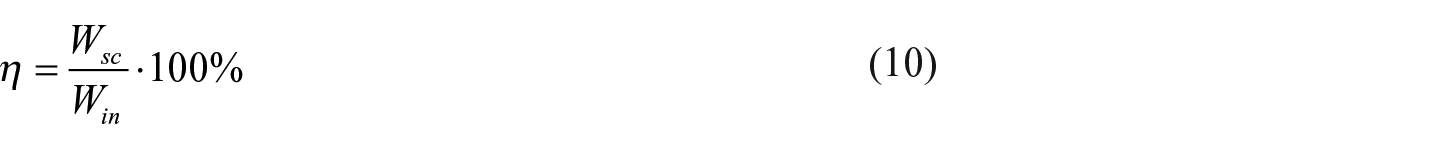


In the above equation, η is the energy-regenerative efficiency, Wsc is the recovery energy of the super capacitor, Win is the energy generated by the two terminals of the energy-regenerative circuit, C is the capacity of the super capacitor, Uc1 is the ended terminal voltage of the super capacitor, Uc0 is the initial terminal voltage of the super capacitor, Um is the input voltage of the energy-regenerative circuit, i is the current in the energy-regenerative circuit, and t is the time.
According to equation (11), the recovery energy of the super capacitor is related to the initial terminal voltage, and thus it is essential to know how the dynamic indexes will change when there are variations of the initial terminal voltage. To determine the initial terminal voltage of the super capacitor, the initial voltage is set from 1 to 30 V. The simulations are carried out in the MATLAB/Simulink software, and the step is set as 0.002 s. The parameters of the hybrid vehicle suspension in the simulation are shown in Table 1. Assume that the vehicle is driving at a speed of 20 m/s on the grade C road. Figures 7 through 10 show the variation of energy-regenerative efficiency, vehicle body acceleration, suspension deflection, and dynamic tire load.
Vehicle parameters.


Variation of the energy-regenerative efficiency.

Variation of the vehicle body acceleration.

Variation of the suspension deflection.

Variation of the dynamic tire load.
It can be inferred from Figures 7–10 that,
In the range of the selected initial terminal voltage, the energy-regenerative efficiency of the hybrid suspension system will become larger with the increase of terminal voltage. When the terminal voltage rises to 23 V, the energy-regenerative efficiency of the hybrid suspension system tends to be stable.
There is an irregular change in the vehicle body acceleration and the dynamic tire load, but the variation range is very small.
When the terminal voltage of the super capacitor changes, the suspension deflection of the suspension is a constant, which indicates that, the suspension deflection of the suspension has no relationship with the terminal voltage.
With the goal of obtaining the maximum energy-regenerative efficiency, the terminal voltage of the super capacitor is selected as 23 V.
Simulation analysis
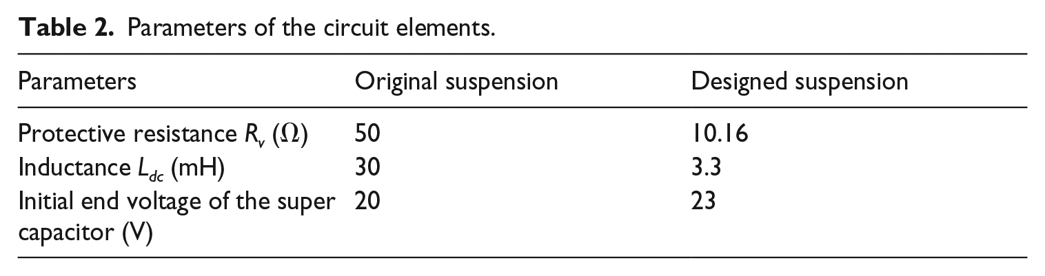
On the basis of the designed energy-regenerative circuit, the detailed parameters of the circuit elements are shown in Table 2.
Parameters of the circuit elements.
On the basis of the parameters, Figures 11 and 12 show the time responses and the frequency responses of the vehicle body acceleration and the dynamic tire load. Figure 13 shows the terminal voltage of the super capacitor when the vehicle is also driving at a speed of 20 m/s on the grade C road.

Responses of vehicle body acceleration.

Responses of the dynamic tire load.
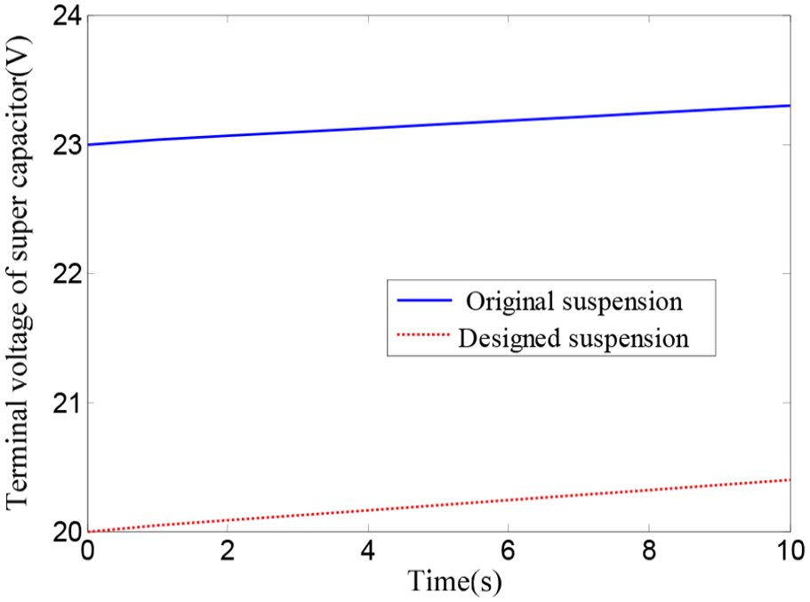
Responses of the terminal voltage of the super capacitor.
The root mean square (RMS) of all dynamic performance indexes of the hybrid vehicle suspension are calculated and listed in Table 3.
RMS of the simulation results.

RMS: root mean square.
It can be seen that the ride comfort of the hybrid suspension is slightly improved from that in Figure 11(a) especially in the low frequency. For the handling stability performance, the RMS of the designed hybrid suspension is slightly decreased compared to the original suspension. Meanwhile, there is no change of the RMS of the suspension deflection. At the same time, the energy-regenerative efficiency of the hybrid suspension can be calculated and is shown in Table 4.
Results of the energy-regenerative performance.

As shown in Table 4, the feed-in energy is slightly reduced, but the energy-regenerative efficiency of the designed hybrid suspension is 10.9% higher than that of the original suspension system. It is indicated that the designed hybrid suspension system is more effective in recovering the vibration energy because the changing of the key coefficients of the circuit elements according to the analysis of the variation of the energy-regenerative efficiency in “Design of the energy-regenerative circuit” section.
Experimental study
Finally, the bench test was carried out on the INSTRON 8800 vibration test rig, and the bench layout is shown in Figure 14. The other tools used in the bench test include the acceleration sensor, displacement sensor, LMS data acquisition unit, stabilized voltage power supply, three-phase rectifier, current sensor, voltage sensor, and oscilloscope. The dSPACE was also used to control the interruption of the MOS tube in the energy-regenerative circuit.
Bench layout.
Figure 15 shows the damping performance of the regenerative suspension, it is noted that, the damping coefficient of the linear motor is a constant. When considering the damper, the damping performance of the regenerative suspension is a nonlinear model because the damping in the compression stroke and stretch stroke is different. In the bench tests, the acceleration sensor was used to detect the acceleration of the vehicle body, and the displacement sensor detected the suspension deflection. The voltage sensor detected the input voltage of the energy supply circuit, and the current sensor detected the current in the circuit. The LMS data acquisition instrument was used to collect the data, and the oscilloscope was used to collect the voltage data and current data. Table 5 shows the results of the bench tests at a speed of 20 m/s on the grade C road. Table 6 gives the energy-regenerative results for different experiments. Because the changes of the suspension deflection and dynamic tire load in Table 5 are very small, Figure 16 only shows the responses of the vehicle body acceleration results in the bench tests.
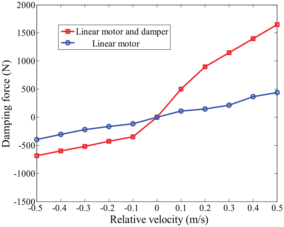
Damping performance of the regenerative suspension.
Results of the bench tests.
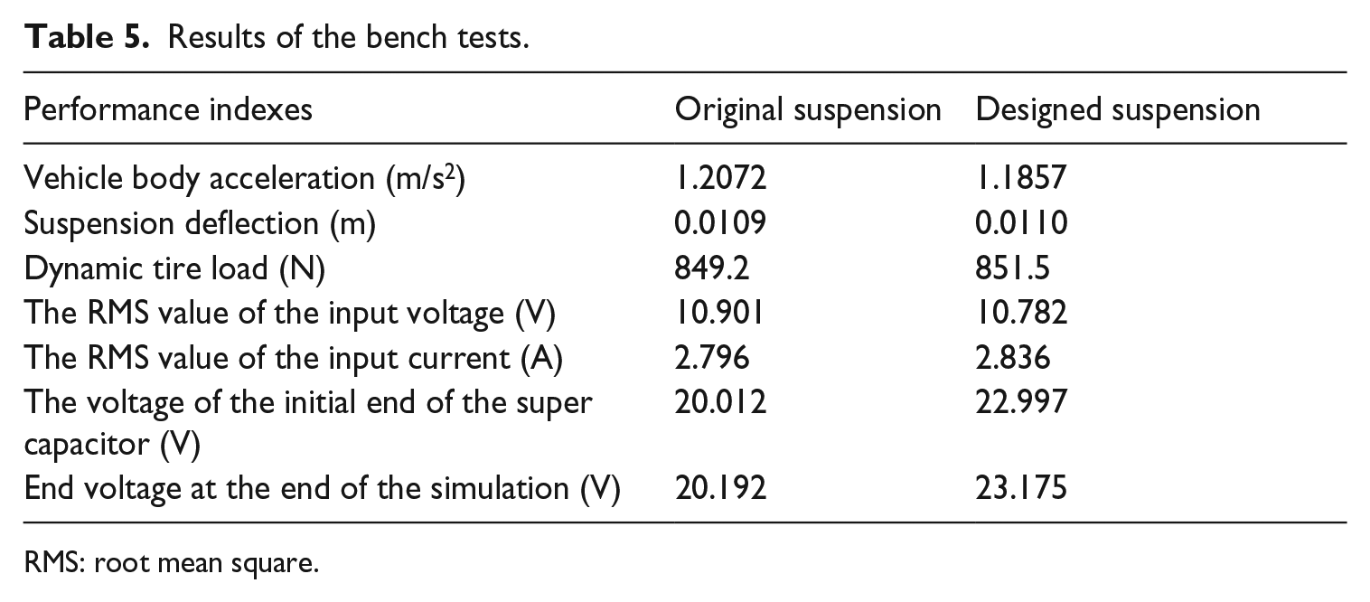
RMS: root mean square.
Energy-regenerative results.


Vehicle body acceleration responses in the bench test.
From the above comparisons, it can be seen that the RMS of the vehicle body acceleration is slightly improved in the hybrid suspension system from 1.2072 to 1.1857 m/s2 compared to the original suspension, while there are very slight changes of the RMS of suspension deflection and dynamic tire load. For the energy-regenerative results at different speeds in Table 6, it can be seen that, the recovery energy of the designed hybrid suspension is significantly improved from 21.148 to 24.869 J at a speed of 10 m/s, from 30.153 to 34.244 J at a speed of 20 m/s and from 36.456 to 40.548 J at a speed of 30 m/s. The energy-regenerative efficiency is improved from 9.5% to 10.6% at a speed of 10 m/s, from 9.9% to 11.2% at a speed of 20 m/s, from 9.8% to 10.9% at a speed of 30 m/s. By comparison to the simulation results shown in Table 4, the improvement of the energy-regenerative efficiency is 11.5%, 13.1%, and 11.2% at speeds of 10, 20, and 30 m/s, respectively. In a word, both the recovery energy and the energy-regenerative efficiency under the different experimental conditions are improved.
Conclusion
This article investigated the design problem of the energy-regenerative circuit in a hybrid vehicle system by considering both the vehicle suspension performance and the energy-regenerative efficiency. The hybrid suspension system was introduced and the dynamic model was established based on a general quarter car model where the simulation results were verified based on bench tests. Then, the protective resistance, inductance, and initial terminal voltage of the super capacitor were analyzed and their impacts on the dynamic performance indexes and the energy-regenerative efficiency were studied in detail. Simulations were carried out to compare the performance of the designed hybrid suspension system with that of the original suspension. The dynamic performance of the hybrid suspension was found to be slightly improved, while its energy-regenerative efficiency was greatly improved. Experimental results indicated that the recovery energy of the designed hybrid suspension was significantly improved, and the energy-regenerative efficiency was improved by 11.5%, 13.1%, and 11.2% at speed of 10, 20, and 30 m/s, respectively, which verified the correctness of the theoretical analysis.
Footnotes
Data availability statement
All of the data in the manuscript are public and no additional data are available.
Declaration of conflicting interests
The author(s) declared no potential conflicts of interest with respect to the research, authorship, and/or publication of this article.
Funding
The author(s) disclosed receipt of the following financial support for the research, authorship, and/or publication of this article: This work was supported by the National Natural Science Foundation of China (Grant No.51705209), Key Research and Development Program Projects in Zhenjiang and the Natural Science Foundation of Jiangsu Province (BK20160533).