
Abstract
As the key to the movement of automated guided vehicle (AGV), the design of control algorithm directly affects whether AGV can follow the preset path. Aiming at the difficulty of AGV control, an AGV path tracking control method based on global vision and reinforcement learning is proposed. Firstly, the global view is obtained by the visual sensor, and the position information of obstacles and AGV is obtained by the target detection algorithm. Secondly, the path planning algorithm is used to obtain the driving path information which is used to establish a virtual environment. Thirdly, the position and pose of the physical AGV are introduced into the virtual environment by the visual sensor, and the virtual AGV is reset. Finally, the image obtained by virtual vehicle camera is input into the reinforcement learning model and the output action is sent to the physical AGV for execution. In the experimental part, this method can not only plan the driving path in different environments but also well control AGV to drive along the specified path, which proves that this method has strong robustness and feasibility.
Introduction
Automated guided vehicle (AGV) is an intelligent industrial transport device, which has the characteristics of high autonomy, flexibility, programmable control, and applicability. Therefore, it is considered to be one of the most promising technologies.1,2 At present, it has become an important part of industrial production intelligence and automation and has become a key equipment in flexible manufacturing systems and logistics automatic transmission systems. 3 However, AGV is a strong coupling and time-varying nonlinear complex system, which is easily disturbed by uncertain factors in the operation process. This uncertainty will lead to AGV deviating from the preset path. Therefore, the quality of its control algorithm plays a decisive role in whether AGV can complete the transportation task.
Current traditional control algorithms can be divided into model-based and model-free algorithms according to different characteristics. Model-free algorithm mainly includes classical Proportional-Integral-Differential (PID) control algorithm and fuzzy control algorithm. 4 In PID control, Zhang et al. 5 used PID algorithm to control the real-time speed of AGV drive motor, so as to improve the path tracking accuracy of AGV. Wang et al. 6 used PID control algorithm to construct AGV steering control system to reduce the center deviation in the process of AGV steering. He et al. 7 used PID algorithm to adjust the speed of direct-current (DC) motor to correct the pose of AGV in real time. However, PID control learning and adaptive ability is relatively weak, in the case of external disturbances, the controller effect may be unstable. If combined with other related technologies to solve the problem of PID adaptability is weak, such as genetic algorithm 8 or particle swarm algorithm, 9 there may appear large overshoot and lead to fall into local optimum or other problems. In fuzzy control, Wang et al. 10 used fuzzy control algorithm on four-wheel independent steering robot to achieve high-precision tracking control. Awad et al. 11 proposed a multi-input and multi-output linear prediction model based on fuzzy control to achieve the purpose of optimizing the steering angle and steering speed. Ren et al. 12 output real-time adjustment of AGV forward speed and rotation angular velocity through fuzzy control algorithm. The quality of fuzzy control depends on the fuzzy membership rules formulated by professionals, and the robustness of the established model is poor. With the change in the environment, a lot of adjustment parameters are needed.
Model-based control mainly includes inversion control and sliding mode control. In the inversion control, Mahgoub et al. 13 designed the robot tracking controller based on the inversion control idea and finally realized the curvature continuity at the joint. Pan et al. 14 use inversion control algorithm combined with nonlinear exponential observer method to obtain the motion law, in order to achieve high-precision trajectory tracking control objectives. However, inversion control is applicable when the system model is determined, otherwise there will be many limitations. And the Lyapunov function of inversion control needs to be redesigned as the system changes, which increases the difficulty of controller setting. In the sliding mode control, Sun et al. 15 introduced a new approaching synovial control algorithm to improve the control performance of the inspection robot. Zhang et al. 16 linearized the established system through linear transformation method and designed the sliding membrane structure controller to realize the reverse path tracking. However, it is difficult for the sliding mode control to slide along the sliding mode toward the equilibrium point. Instead, it fluctuates up and down on both sides to reach equilibrium, which will cause jitter and affect the actual use.
With the development of deep learning technology, reinforcement learning is gradually applied to various fields. In the field of AGV, reinforcement learning is mainly applied to AGV path planning, AGV scheduling, and adjustment parameters. Liu et al. 17 proposed an Improved Dyna-Q algorithm for AGV path planning in large complex dynamic environments. This algorithm can effectively reduce the path search space and improve the efficiency of obtaining the optimal path. Sagar et al. 18 proposed a real-time AGV scheduling strategy based on reinforcement learning technology, which uses a novel deep reinforcement double Q-learning method to schedule different AGVs to different states. Sierra-Garcia et al. 19 proposed an intelligent hybrid control scheme that combines reinforcement learning-based control with conventional Proportional-Integral (PI) regulators. In this control scheme, PID is used to control the speed of two AGV wheels, and the parameters of PID are adjusted by reinforcement learning algorithm, which makes the path tracking mode strong robustness.
In general, there are few reinforcement learning algorithms that directly control AGV dual wheel for path tracking. Aiming at the problems existing in traditional path tracking algorithms, this paper proposes an AGV path tracking control method based on global vision and reinforcement learning in undisturbed indoor environment with varied layout. This method has strong adaptability and portability, and does not need to redesign the control function when replacing the mobile environment or mobile devices. In the experimental part, the results verify that the proposed control method has strong robustness.
The paper is organized as follows: In the section “Path tracking process and reinforcement learning algorithm”, the control method flow and reinforcement learning algorithm are introduced. In the section “Virtual environment building and model training”, the training environment required by reinforcement learning is set up and the reinforcement learning model trained in the virtual environment is retrained in the real environment via transfer learning. In the section “Physical model validation”, the reinforcement learning model is transplanted to the physical AGV to verify the feasibility of the proposed method. Finally, the fifth section concludes this article.
Path tracking process and reinforcement learning algorithm
Path tracking process design
The path tracking process based on global vision and reinforcement learning is shown in Figure 1.

Path tracking flow chart based on global vision and reinforcement learning.
The first step is to obtain position information of AGV and obstacle by using the image obtained by the vision sensor through the target detection algorithm.
The second step is to generate a binary map based on the AGV and obstacle information obtained in first step, and use the obtained binary map as the input graph of the path planning algorithm to plan the walking path of the AGV intelligently.
The third step is to establish a virtual environment based on the planned path information and load the reinforcement learning model to complete the training.
The fourth step is to get the image by the global visual sensor and obtain the position and pose information of AGV by identifying the vehicle marks.
The fifth step is to input the information obtained in the fourth step into the virtual environment. The current virtual vehicle camera image is obtained by resetting the AGV pose and position in the virtual environment. Then the image is input into the reinforcement learning model and the action in the current state is obtained.
The sixth step is to execute the action sent by the fifth step on the actual AGV and judge whether to reach the destination position. If so, the program is terminated, otherwise, it jumps to the fourth step.
Selection and design of reinforcement learning algorithm
Theoretical basis of reinforcement learning
Reinforcement learning is a popular machine learning method in recent years. Its basic idea is to obtain reward value by interacting with the environment and carrying out self-learning according to this value. Reinforcement learning mainly includes agent, environment, action, state, and reward, and its relationship is shown in Figure 2. 20
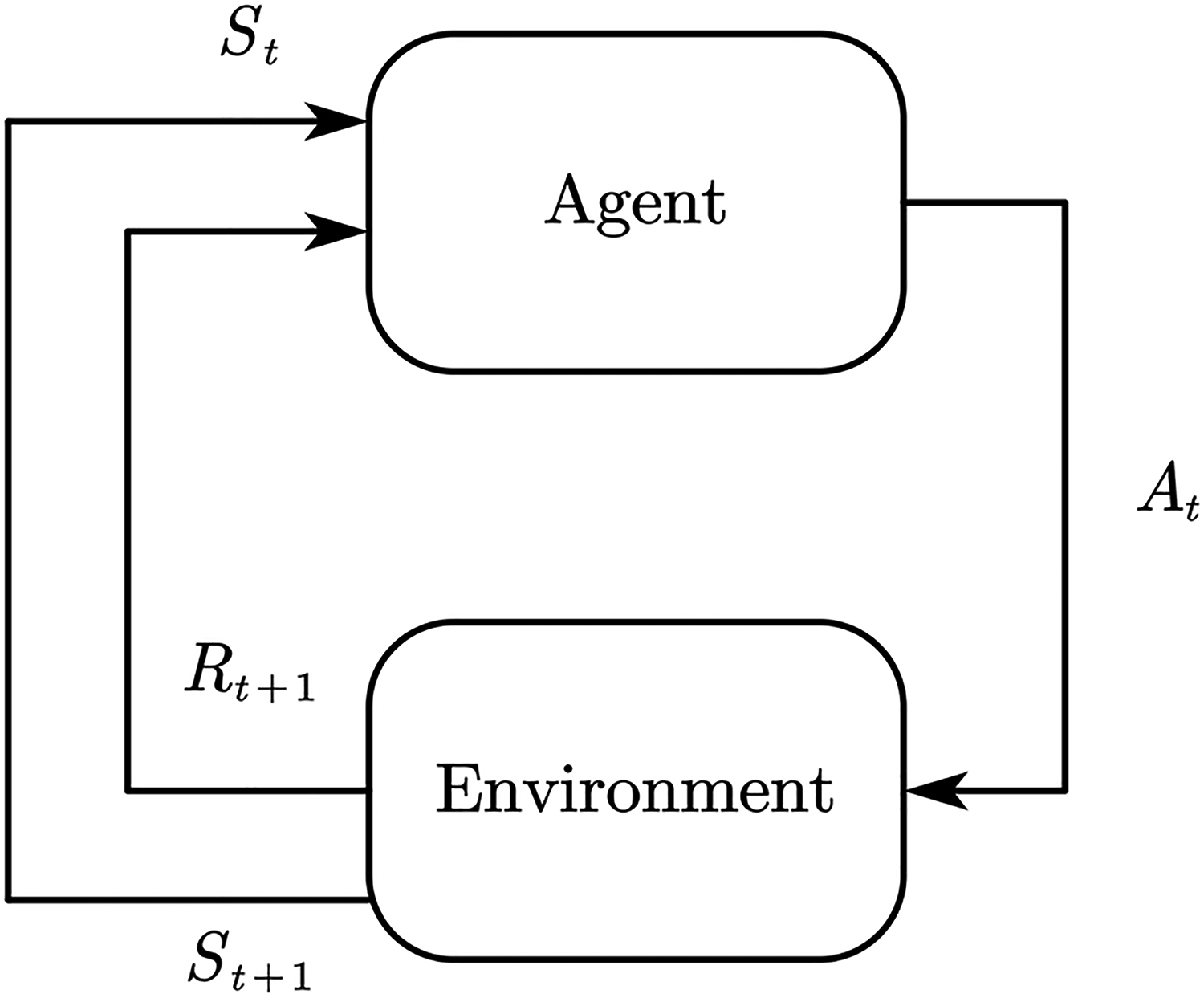
Reinforcement learning diagram.
In any time step, the agent first observes the state
DeepMind team formally proposed deep reinforcement learning in 2013 to implement end-to-end learning by combining deep learning with reinforcement learning. 22 The rapid development of deep reinforcement learning has produced many excellent reinforcement learning algorithms, which are mainly divided into value-based methods and policy-based methods. 23
Value-based reinforcement learning algorithm is to obtain the optimal value function through training to make decisions, and select the actions corresponding to the maximum value function in each decision-making process. The representative algorithms include Q-learning, State-Action-Reward-State-Action (SARSA), etc., which are characterized by high sample utilization rate, small variance of estimated value of value function, and not easy to fall into local optimal, but prone to overfitting and only suitable for discrete space. 24
The main way of the policy-based reinforcement learning algorithm is to train both the value function and the policy function in the training process, and only rely on the policy function after the training. The representative algorithms include proximal policy optimization (PPO) algorithm, twin delayed deep deterministic policy gradient (TD3) algorithm, and deep deterministic policy gradient (DDPG) algorithm. PPO algorithm has become the default algorithm of OpenAI due to its advantages such as stable training, simple tuning, and strong robustness. Therefore, this algorithm is selected as the control algorithm of AGV path tracking in this paper.
Theoretical basis of PPO algorithm
Policy gradient (PG)
25
algorithm is a policy-based method. Its principle is to update the policy by calculating the value of the PG and using the random gradient rise algorithm. The most widely used gradient calculation formula is shown in Equation (1).

However, the traditional PG algorithm is difficult to obtain good results in practical problems, because the gradient policy update is very sensitive to the selection of step size. PPO
26
algorithm modifies the logarithmic probability gradient of the original PG formula for this problem. The ratio of the action probability of the current policy to the action policy of the previous policy. The mathematical expression is shown in Equation (2), and the objective function of the PG is updated to Equation (3).

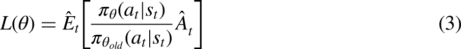

In general, the PPO algorithm first obtains the current state, action, and reward, and then calculates the advantage function and objective function. The parameter
PPO network structure construction
The structure of PPO network in this paper is shown in Figures 3 and 4. Figure 3 is the feature extraction network structure layer of PPO algorithm, and Figure 4 is the structure layer of PPO algorithm policy network and value network.

Feature extraction network structure layer by PPO algorithm.

PPO algorithm policy network structure layer (top) and value network structure layer (bottom).
It can be seen from Figure 3 that the input form of feature network extraction layer of PPO algorithm used in this paper is 84 × 84 × 3 picture. After multiple convolution operations and linear transformation, 64 feature values are finally extracted from this network. Figure 4 shows that PPO policy network and value network take these 64 characteristic values as input. Then, multiple linear transformations are performed, respectively, to output the action controlling AGV movement and value evaluating the current network selection policy.
Virtual environment building and model training
Building virtual environment
The training reinforcement learning network needs to build a virtual environment for algorithm operation, which is mainly used for the training of PPO control algorithm model in this paper. In addition, when the AGV moves, it is necessary to convert the binary map into virtual map and obtain the rotational speed value of the AGV twin wheels.
Pybullet is a Python module based on the famous open source physics engine bullet, which is mainly used for physical simulation of robots, games, visual effects, and machine learning. 27 Pybullet is selected as the virtual environment of reinforcement learning in this paper because it has the characteristics of low difficulty and the simulation results are practical.
The construction of virtual environment mainly includes the establishment of agent model, the setting of virtual path, the input and output of reinforcement learning algorithm, and the setting of reward function of training reinforcement learning model. The components are shown in Figure 5.
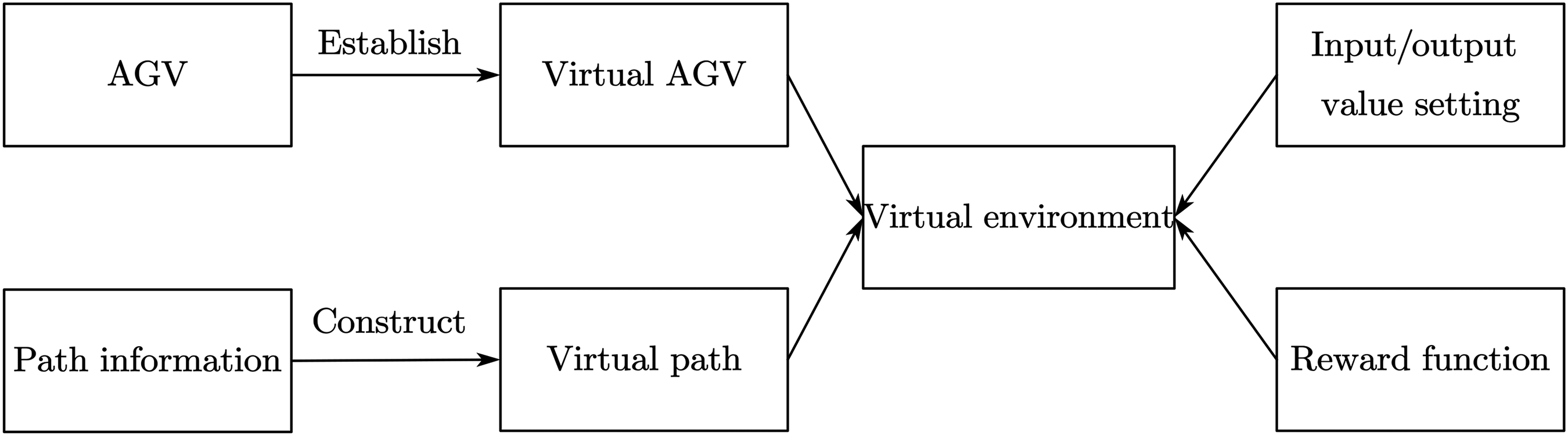
Composition of virtual environment.
The main function of the virtual AGV is to synchronize the pose information of the AGV to the virtual environment through the established model. The main purpose of setting the virtual path is to synchronize the planned path information to the virtual environment by constructing virtual points and lines. After setting the virtual AGV and virtual path, a reasonable observed value should be selected as the input of the reinforcement learning algorithm, and the size of the output value controls the movement of the virtual AGV. Finally, in order to make the virtual AGV travel along the planned path, a reward function limiting AGV movement should be set, which can guide the virtual AGV to move along the path during reinforcement learning training.
Agent modeling
In order to verify the effectiveness of the proposed algorithm, a two-wheel differential car with flexible movement but high control difficulty is selected as the control object in the experiment. The kinematics model is shown in Figure 6.28,29

Kinematic simplified model of two-wheel differential AGV.
AGV is driven by two motors independently, and the rotation center is the center of two wheels. According to the motion model of AGV, the current position of AGV is estimated. The relationship is as follows:


Assuming that the coordinate of the mobile robot in the two-dimensional coordinate system is (x, y), and the angle


According to the above principle, the three-dimensional model is established as shown in Figure 7. The model has three coordinate systems, namely, the base coordinate system, the left-wheel coordinate system, and the right-wheel coordinate system. The establishment of the left-wheel coordinate system and the right-wheel coordinate system is mainly used to control AGV moving in the virtual environment. The establishment of the base coordinate system is used to determine the position of the car and determine whether the car walks according to the specified path.

3D model diagram of AGV.
Virtual path setting
In this paper, after obtaining the location information of AGV and obstacles, the path planning algorithm is needed to obtain the AGV travel path information, and the information is introduced into the virtual environment. Among the common path planning algorithms, A-Star(A*) 30 algorithm is the most effective direct search method for solving the shortest path in a static road network. It is widely used in path planning tasks because of its good performance and accuracy. Therefore, this paper selects this algorithm as the planning algorithm.
In path planning, A* algorithm searches the node as a unit, so the final path is the connection between the node and the node. According to this feature, in the path information transmission, only the coordinate position of the path turning point is introduced into the virtual environment, and the effect is shown in Figures 8 and 9.

Binary graph of path planning.

Import paths to the environment.
Figure 8 is a binary map after the implementation of A* path planning, and its path turning point information and driving route have been annotated in the map. Figure 9 shows the virtual environment after loading the turning point of the path. The black thin line represents all the paths that AGV needs to walk, the red thick line represents the path that AGV needs to walk in the current stage, and the yellow point represents the target point in the current stage. When the AGV reaches the current stage target point, it will determine whether there is a next stage target point. If any, open the next stage path and the target point to continue the path tracking, the effect is shown in Figure 10, otherwise, the AGV reaches the target point to complete the tracking task.

Reach current phase target point and open next phase target point.
Observation value and output action setting
As the input of reinforcement learning algorithm, different observation values will train different network strategies. In this paper, the reinforcement learning model needs to realize the path tracking task, so the observation value should include path information and point information. Based on this, the paper uses virtual vehicle camera to obtain the above required information, and its structure is shown in Figure 11.

Structure diagram of vehicle vision sensor.
It can be seen from Figure 11 that the field of view of the virtual vehicle vision sensor is 60°. In order to obtain a wider field of view, the angle between the optical axis direction and the vertical direction of the vision sensor is set to 60°. Setting the parameter into the virtual environment, the effect is shown in Figure 12.

Virtual camera shooting mode diagram.
It can be seen from Figure 12 that the set virtual camera can well obtain the path and the target point information of the current stage, which proves the rationality of the set parameters.
The above image is taken as the input image of reinforcement learning algorithm, and the output result is set as the rotational speed value of the left and right wheels of AGV. The value is between [−1, 1], where the symbol represents the steering of the wheel, and the value represents the rotational speed of the wheel. In this paper, the two-wheel speed of AGV is matched with the two-wheel speed of virtual environment by proportional amplification.
Training reward setting
The setting of reinforcement learning reward function is mainly to specify and digitize the target task, so that the agent can obtain the reward value of the selected action and determine the direction of the next action update. Its design directly determines whether the training model can converge quickly and whether the agent can acquire the correct policy. In the path tracking task in this paper, the reward function should be set by integrating the planned path information and AGV poses information. For this task, the reward function in this paper is composed of multiple factors, and its mathematical as follows:


AGV distance target point diagram.
When AGV moves toward the target point, the reward value is positive, while when AGV moves away from the target point, the reward value is negative. Therefore, the setting of this value effectively ensures that AGV moves toward the target point continuously.

AGV axis and path angle diagram.
When the angle between AGV direction and path direction becomes smaller, the reward value is positive, otherwise is negative. The setting of the reward value enables AGV to travel along the planned path direction during the training process without large angle change in the process of movement.

AGV base point and path distance diagram.
Model training and training results
During the training process, the virtual environment is set to randomly select positions and postures at the beginning of each round to reset the information of the virtual AGV. And seven target points of the path are randomly selected as driving nodes in non-overlapping areas. The connection of these seven target points is used as the driving path of the AGV, and the effect is shown in Figure 16. The center of the picture is the global visual image, and the left is the images captured by virtual vehicle camera.

Virtual environment information reset diagram.
After simple debugging, the final training parameters adopted by PPO algorithm are shown in Table 1.
PPO algorithm training parameters.

Basic Parameter of AGV.

The results of reinforcement learning training model are shown in Figure 17, where the abscissa is the training time step and the ordinate is the loss value. The total step size of the model training is 8 million times. In the first 1 million step size, the loss function of PPO network shows a trend of increase and then decrease with the oscillation. In the 1 million to 5 million step size, the loss function of the network shows a slow downward trend. And in the last 3 million step size, the loss function of the network shows a gentle trend, which proves that the model has reached convergence after training 8 million step size.

Loss curve of PPO algorithm.
The trained model is put into the virtual environment for testing. The global planning path is set as a black line, and the AGV actual walking path is set as a blue line. The effect is shown in Figure 18.

Virtual environment test diagram.
In Figure 18, the reinforcement learning model finally trained has the ability of rotating in place, correcting deviation, and walking in straight line. When vehicle visual sensor views there is no yellow target and the red path image will spin around looking for target and path. When visual sensor captures target point and path information vehicle will be to move. And according to the target and the path the image in different position, so as to constantly adjust the AGV two rounds of speed. Finally, the AGV runs along the preset path and arrives at the set point.
Transfer learning
The control policy obtained from the virtual environment model cannot be directly applied to the actual environment, because there are certain differences between the virtual environment and the actual environment, as well as between the virtual AGV and the actual AGV. The actual environment and AGV are often more complex and time-varying. Therefore, in order to ensure the actual AGV moving accuracy, this paper puts the control model in the virtual environment into the actual environment for transfer learning.
In this paper, the way of transfer learning is model transfer, which is to train the control model in the virtual environment in the actual environment. The training method is shown in Figure 19.

Model transfer training diagram.
Firstly, AGV is randomly placed in the driving area, and then point A and any point B are selected as the driving path of AGV. Then, the AGV is controlled to drive according to the path. After reaching the selected point B, point A and other point B are selected as the driving path, so that the AGV is controlled to move repeatedly and the reinforcement learning adjustment control policy is continuously carried out. The final loss value of reinforcement learning in the actual environment is shown in Figure 20.

Model transfer loss curve.
The loss value of model transfer is shown in Figure 20. PPO_1 training is carried out first. The loss value shows a downward trend from the orange line in Figure 20, but the loss value of this training does not finally tend to be flat. Therefore, the second training continued on the basis of PPO_1 model, and the PPO_2 model was finally obtained. From the blue line in the graph, the loss value shows a gentle trend, which indicates that the model PPO_2 has converged.
Physical model validation
In order to verify the reliability and feasibility of the method proposed in this paper, Arduino is used as the control board, the stepper motor is used as the driver, and the Apriltag is used as the sign board component. AGV is shown in Figure 21.

Physical AGV.
The parameter is shown in Table 2.
Experimental process
Firstly, the global vision sensor is used to obtain the image of AGV driving area, as shown in Figure 22.

Image taken by vision sensor.
Secondly, the obstacle information and vehicle information in Figure 22 are obtained through target detection algorithm. The binary map is established with obstacle information. Then the binary map is used as the input map of the path planning task. The starting point is the center point of the two rounds of AGV, and the end point is the manual selection point. The effect after the planning is shown in Figure 23. Figure 23(a) is the binary graph after path planning, and Figure 23(b) is the physical graph drawing the planned path information.

Path planning.
The planned path information and AGV pose information are input into the virtual environment, so that the virtual environment can establish virtual path, virtual AGV, and virtual target points similar to the real environment, as shown in Figure 24.

Virtual environment establishment.
Through the global vision sensor, the actual AGV pose and position information is continuously introduced into the virtual environment. And the AGV in the virtual environment is also reset. The virtual vehicle shooting map under this pose is input into the trained reinforcement learning model. Finally, the action output from the reinforcement learning model is sent to the actual AGV for execution. By continuously repeating the above process, AGV is controlled to reach the designated position. The effect is shown in Figure 25.

AGV moving diagram.
In Figure 25(a), the blue line is the virtual AGV moving path, and the red is the planning path. In Figure 25(b), the black point is the actual AGV moving path, and the black line is the planning path. It can be seen from Figure 25(b) that AGV can reach the target point according to the planned path through the above way, which effectively proves the feasibility of the method proposed in this paper.
Different layout experiment
In real life, different application scenarios have different layouts. In order to verify the robustness of the method described in this paper, different layouts are simulated by placing different positions and numbers of obstacles in the experiment.
In this paper, single obstacle, double obstacle, three obstacle, and five obstacle maps are used as the driving environment of AGV. With the increase of obstacles, the longer the path AGV needs to travel, the more turning points need to pass. This setting method can well test the robustness and tracking ability of the path tracking algorithm, as shown in Figure 26.

AGV mobility diagram under different layout environments.
From the actual driving path of AGV in Figure 26, it can be seen that the reinforcement learning algorithm trained in this paper has a strong ability to move and correct deviation and to decelerate at the inflection point. The correction ability can ensure that AGV can timely adjust the wheel speed and move to the preset path when it deviates from the planned path due to external factors. The deceleration capacity at the inflection point can ensure the smooth running of AGV at the turning point and the stop accuracy of AGV.
In order to check the moving accuracy of the proposed algorithm, 60 moving experiments are carried out in a single obstacle environment, and the maximum path displacement deviation and stop deviation in each experiment are recorded. The experimental results are shown in Figures 27 and 28.
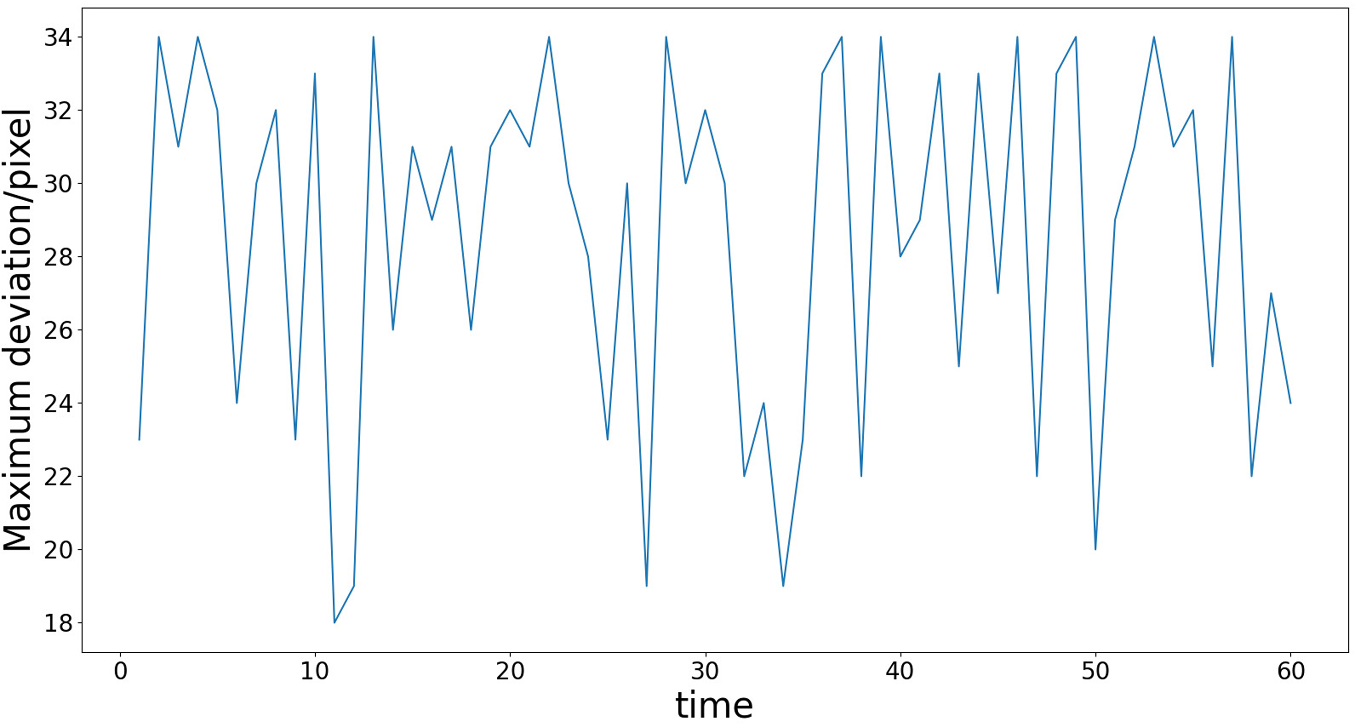
Maximum path displacement deviation.
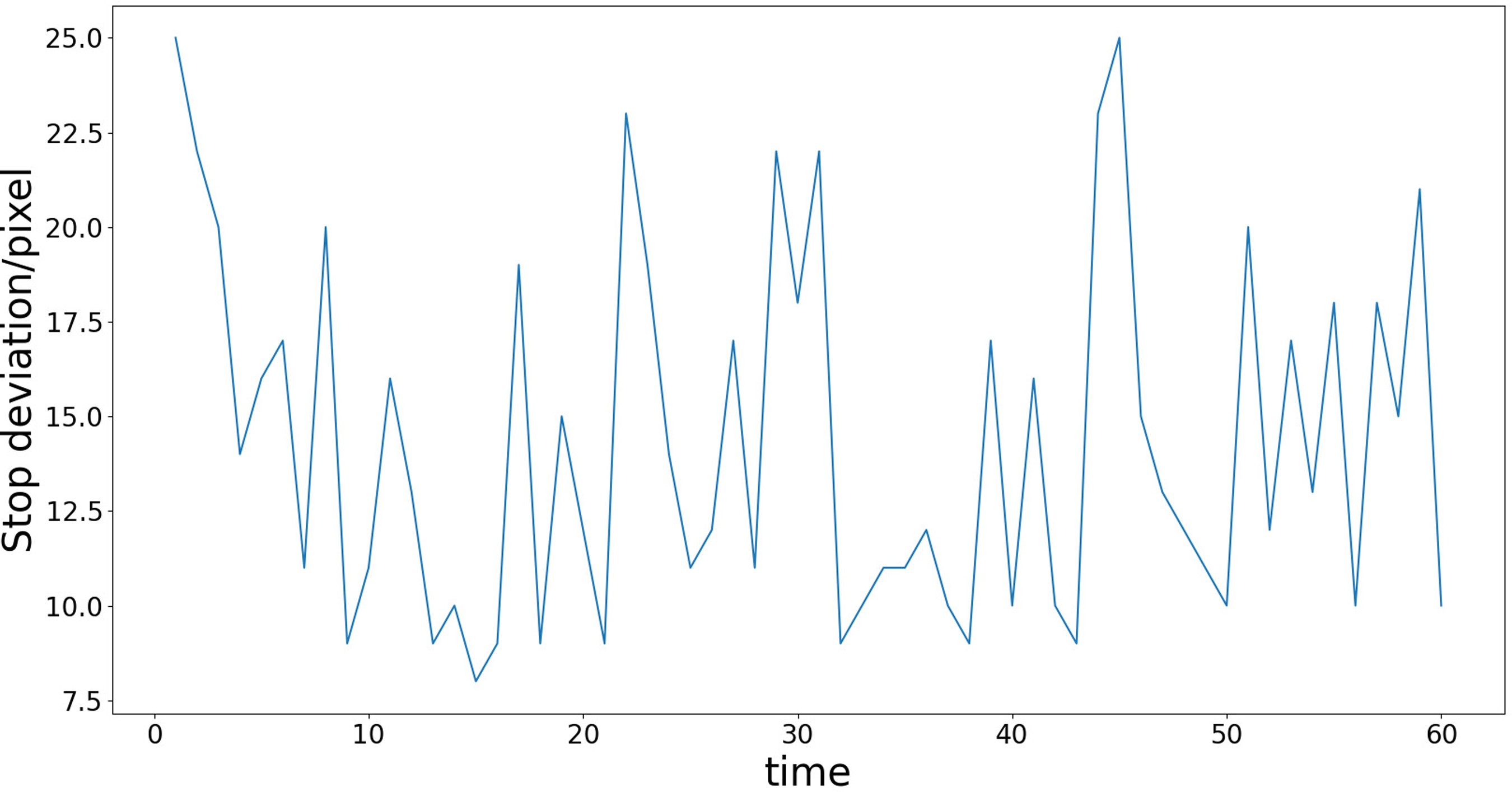
Stop deviation.
Finally, the average maximum path displacement deviation is 28.6 pixels, and the average stop deviation is 13.9 pixels. The actual deviation distance is related to the resolution of the visual sensor. For example, under the version of vision sensor used in this paper, it can be seen through measurement that the length of 180 mm occupies 200 pixels. Therefore, by calculating the ratio of 9:10, the average maximum path displacement deviation is 25.74 mm and the average stop deviation is 12.51 mm. If a visual sensor with higher pixels is used and the ratio of length to pixels is reduced, the actual error of the final movement will be smaller. In addition, the AGV movement accuracy is also affected by the reinforcement learning training conditions. If the proportion of Rd in the reward value setting is increased, the trained model will have smaller AGV movement displacement deviation, but this setting will also increase the difficulty of model convergence.
Conclusions
This paper proposes an AGV path tracking control method based on global vision and reinforcement learning. This method first detects the target of the global image to obtain the obstacle information of the map and the position and orientation information of AGV, and then establishes a binary map and conducts path planning. The planned path information is mapped to the virtual environment, and the two-wheel speed value of AGV is obtained by continuously resetting the virtual AGV. Finally, the speed value is sent to the actual AGV for execution until the AGV reaches the destination.
The method is verified in the section “Physical model validation” of the experiment. The final experimental results show that the method described in this paper can not only well complete the path planning tasks under different layout environments, but also the reinforcement learning algorithm can control AGV to travel according to the specified path and finally reach the destination, which proves that the method described in this paper has adaptability and feasibility. Compared with the algorithm which needs a large number of sensors and carries out route planning in advance, the advantage of the proposed algorithm in this paper is low price and strong flexibility.
The experimental background of the proposed path tracking technology is undisturbed indoor environment with variable layout. In future work, this technology can be used as a basis for expansion, such as adding obstacle recognition sensors to achieve AGV mobile obstacle avoidance, and establishing a virtual environment matching the real environment to achieve automated driving, etc.
Footnotes
Declaration of conflicting interests
The author(s) declared no potential conflicts of interest with respect to the research, authorship, and/or publication of this article.
Funding
The author(s) disclosed receipt of the following financial support for the research, authorship, and/or publication of this article: This work was supported by the Key R&D Project of Zhejiang Province (2022C01242), Longgang Institute of Zhejiang Sci-Tech University (LGYJY2021004), and Zhejiang Provincial General Scientific Research Projects Fund of China (Y202148127).