
Abstract
With the change of manufacturing mode and the progress of science and technology, the traditional manufacturing industry has gradually developed to intelligent manufacturing and flexible manufacturing. To achieve factory transformation, Automatic Guided Vehicle (AGV) is indispensable. In this paper, an AGV trackless guidance technology based on global vision is proposed. Firstly, the global vision camera is used to obtain the image of the AGV driving area, and then the obstacle information and position information of the AGV are obtained by image processing technology. Secondly, the A* algorithm is used to intelligently plan the AGV driving path, and the wireless network communication is used to control the AGV driving according to the planned path. Experiments show that the method is feasible and has the advantages of high flexibility, high precision, low cost and strong expansibility, which is of great significance to the realization of intelligent warehouse and unmanned chemical plant.
Introduction
With the development of manufacturing industry, the traditional manufacturing and transportation mode gradually cannot meet the current logistics demand, which makes the application of intelligent technology in warehouse storage more and more significant. Automatic Guided Vehicle (AGV), a kind of mobile robot used for material handling, is considered to be one of the most promising technologies owing to its high autonomy and applicability.1–6 It is widely used in material supply operations in various workshops and warehouses, and becomes an indispensable part of intelligent factories.7–9 However, AGV positioning and guidance technology is the key and difficult point in the production, manufacturing and application of AGV at present. The quality of positioning and guidance technology has a great influence on whether AGV can meet the requirements of autonomous operation.10,11 In this paper, according to whether AGV has a fixed guiding line, AGV guidance can be divided into trajectory guidance technology and trackless guidance technology. 12
In today's technological context, trajectory guidance technology for navigation control of AGVs through pre-set fixed paths has been widely used. 13 The design idea is to obtain the information of the car ‘s movement through a variety of sensors mounted on the AGV, such as position, speed, acceleration, direction of motion, etc. The collected information is compared with the pre-designed information to obtain the difference between the actual running path of the AGV and the set running trajectory, and then adjust the movement trend of the AGV according to difference. 14 The trajectory guidance technology includes the electromagnetic guidance technology, two-dimensional code guidance technology and trajectory visual guidance technology. In electromagnetic guidance technology that relies on the fixed magnetic wire to complete the material handling, Cho et al. 15 presented an improved positioning method for Magnetic Encoder type Guided Vehicle using the Extended Kalman Filter and Encoder Compensation Method. Zhou et al. 16 combined electromagnetic guidance with radio frequency identification technology and used three different path selection methods to overcome the limitations of electromagnetic navigation technology which could not adapt to complex paths. Two-dimensional code guidance technology which corrects the deviation by affixing two-dimensional code on the road and obtaining the code's information by camera at the bottom of the AGV. Xu et al. 17 proposed a visual navigation automated guided vehicle system based on quick response (QR) code, and the experimental research shown that in the process of the navigation, the site location error of AGV had been greatly improved after revision. In trajectory visual guidance technology which controls AGV movement by pasting ribbons path and identifying the set path using image processing technology, 18 Zhang et al. 14 proposed a dynamic threshold transfer and segmentation method to solve the problem of uneven light in the process of AGV travel. Liu et al. 19 proposed a design of composite navigation control system based on vision, which recognized the station with radio frequency identification firstly, then AGV built an image recognition system with visual technology to achieve the accurate positioning.
Trajectory guidance technology has high positioning accuracy and simple navigation mode, so it can make AGV walk according to the specified path without too many algorithms. However, compared with trackless guidance technology, this technology has low flexibility and limitations in application scenarios. For factories that need to regularly change production modes and update equipment, this guidance technology is difficult to re-plan paths according to the new environment.20,21 Therefore, the trackless guidance technology with the characteristics of non-fixed path has become the focus of AGV research at this stage.22–25
The control method of trackless guidance technology is similar to the trajectory guidance technology. The main difference is that the path of trajectory guidance technology is predetermined and fixed in the real world, and trackless guidance technology does not need to lay a fixed physical path on the ground. The current trackless guidance technologies mainly include inertial guidance, laser guidance and SLAM (simultaneous localization and mapping).
Inertial navigation technology uses the gyroscope in the inertial measurement unit to measure the rotation angle and the accelerometer and to obtain the translation acceleration, so as to calculate the current positioning, heading pose and other information of the car. 26 Song et al. 27 proposed the method of inertial guidance and QR code to correct the deviation position and the heading deviation of the AGV. Wang et al. 28 proposed the models and algorithms of the data fusion navigation and the obstacle avoidance. The encoder, gyro, acceleration sensor, ultrasonic sensor and infrared sensor were selected to establish the Kalman filter multi-sensor to improve the navigation accuracy of AGV and navigation performance. This technology has high positioning accuracy, strong flexibility and wide applicability. However, the cost of this technology is high, and the accuracy and reliability of the guidance are closely related to the manufacturing accuracy and service life of the gyroscope. With the increase of the use time, the moving error value will be continuously superimposed.
Laser guidance technology installs laser positioning mark (laser reflector with high reflectivity) on the driving path. The laser sensor installed on the AGV collects the laser reflected by the reflector in real time and performs signal processing. The position, attitude and trajectory deviation of the AGV in the environment are calculated in real time, and the AGV is controlled to run along the predetermined path. Luo et al. 29 proposed a new calibration method to solve the problem of position calibration of two-dimensional laser range finder sensor in automated guided vehicles. The attitude of sensors in the vehicle was obtained by solving the trajectory equation and using the sensor attitude information when the vehicle was controlled to move straight. Jung et al. 30 proposed a positioning improvement of a laser navigation system (LNS) using the unscented Kalman filter (UKF) and fuzzy inference system (FIS). Jung et al. 31 proposed a positioning method to improve the performance of the laser guidance system, which integrated two encoders, a gyro sensor and laser guidance through the particle filter. However, the accuracy of AGV movement using laser guidance technology is reduced when it is affected by the specific environment. And to ensure accuracy, more laser positioning signs need to be installed, which makes the technology cost higher.
SLAM techniques can roughly be divided into the visual-based and the LiDAR-based. 32 The principle of both is to obtain the information around the AGV through sensors, and then obtain the attitude and position of the AGV through filtering or feature point extraction, so as to achieve target navigation. Zhou et al. 33 proposed a novel 6-degree-of-freedom visual simultaneous localization and mapping method based on the structural regularity of man-made building environments. R Mur et al. 34 presented ORB-SLAM2 a complete SLAM system for monocular, stereo and RGB-D cameras, including map reuse, loop closing and relocation capabilities. This system included a lightweight localization mode that leverages visual odometry tracks for unmapped regions and matches to map points that allow for zero-drift localization. Olson 35 described an approach for posing a scan matching query over these candidates jointly, finding the best match between a particular pose and a set of candidate poses, or the best match between two sets of poses. Jia et al. 36 proposed a block-based local map correction module that takes both map and pose into consideration to construct accurate constraints. The constraints are then added to the global pose optimization module to significantly reduce the cumulative error of the rough map and thus construct a high-accuracy 2D map. However, visual SLAM is limited by visual sensors and real-time processing speed. The monocular, stereo, and depth camera systems are all sensitive to ambient light and optical textures in the environment. And the captured image may be lack of texture and may also easily get blurred when the platform moves in a high speed. These shortcomings limit the application of this technology.37,38 For LiDAR SLAM, the change of ground material, uneven ground and the change of AGV load will bring great influence on the construction error of odometer. And it is easy to lose localization in a long and straight corridor with walls on both sides or in a dynamic environment.
Therefore, this paper proposes an AGV guidance technology with low cost, high precision, high flexibility and strong expansibility aiming at the existing problems of AGV trackless guidance technology. This technology uses a global camera and an AGV equipped with finite sensors. The position information of AGV and obstacles in the driving area is obtained through the global camera, and the AGV driving route is intelligently planned. Then the command transmission is carried out through the wireless network to control the AGV to the specified position. The guiding technology innovation points are as follows:
The realization of this method mainly relies on camera and image processing technology. AGV does not need to be equipped with too many sensors, which greatly reduces the operating cost of AGV. The guidance path generated by this method is determined by the AGV position and target point. According to the intelligent planning of the walking path of the AGV surrounding environment, the AGV walking path can be adjusted in time and automatically in case of emergencies, with high flexibility. This method can observe the AGV position information in real time through the camera, and realize the AGV automatic path correction and remote-control function in the process of AGV movement. This method controls the AGV movement driven by the camera, and can achieve the yaw angle error within 2 degrees and the positioning error of less than 30 pixels.
The remainder of this paper is organized as follows. Section 2 introduces the overall structure of the autonomous navigation system under global vision. Section 3 introduces the image processing algorithm of autonomous navigation under global vision. Section 4 introduces the AGV control algorithm under global vision. Section 5 design experiments and verify the feasibility of the method. Section 6 provides conclusions for this paper.
Overall design of autonomous navigation system under global vision
Layout and process design of visual guidance system
The main layout of the global vision AGV guidance technology proposed in this paper is shown in Figure 1. The system consists of global camera, marking plate, AGV and master control computer. The camera is located in the upper part of the AGV driving area. The marking plate is fixed on the top of the AGV. The battery, control board and ultrasonic sensor are loaded on the AGV. And the master control computer is located outside the driving area.

Overall layout of autonomous navigation AGV global vision.
It can be seen from Figure 1 that at the same height, the oblique camera shooting method can obtain a larger field of vision, collect more image information and expand the AGV driving area compared with the vertical camera shooting method. In the feasibility verification of Section 5, the oblique angle of the camera is adjusted to be 2 meters from the vertical height of the driving area and 45 degrees with the horizontal line to obtain the image. This oblique angle can not only meet the needs of large field of vision, but also ensure that the image does not have large distortion. The marking plate fixed on AGV can quickly determine its coordinate position after image processing. This method can obtain AGV position information in real time, and achieve the purpose of positioning and tracking. The control board is used to realize AGV mobile control, wireless network communication between AGV and master control computer. The ultrasonic sensors mounted on AGV for mobile obstacle avoidance.
The flow chart of autonomous navigation AGV under global vision is shown in Figure 2.

Autonomous navigation AGV map under global vision.
Firstly, the image obtained by the camera is processed by image processing technology to obtain AGV position information and target position information, and the obstacle position information in the image is obtained by binarization and image gradient operation. Secondly, the binary map is generated by synthesizing the above AGV, target point and obstacle information, and the obtained binary map is used as the input map of the path planning algorithm to plan the walking path of AGV intelligently. Then the control board loaded on the AGV is used as the server to connect the master control computer. By comparing the actual position information and the expected position information of the AGV, the mobile command is sent to continuously adjust the coordinate position and yaw angle of the AGV, and the AGV is controlled to walk according to the specified route. Finally, the ultrasonic sensor is used to determine whether there is an obstacle in the driving direction. If there is a new obstacle, the AGV stops moving, and requests the master control computer to re-plan the path until the AGV reaches the specified location or manually sends the stop command.
AGV hardware selection
According to the overall layout and operation process of autonomous navigation AGV studied in this paper, this paper will verify the feasibility of the algorithm in Section 5. The hardware involved is introduced in detail.
Visual sensor
In this paper, a Hikvision camera with model MV-CA060-11GM/10GC is selected to collect images. The camera uses a special network port line to connect the master control computer, and the transmission rate is faster than the USB interface, which can guarantee the stability of transmission.
After testing, the camera can ensure the transmission of images within 5 meters, which meets the distance requirements of the master control computer and the camera in this study. The camera does not need to connect another image acquisition card, and the image quality obtained meets the needs of this study. The parameters are shown in Table 1.
Communications facilities
Camera parameters.

The data communication between the master computer and AGV is wireless, which can solve the problem of camera separation from AGV in global vision and make AGV system more flexible. 39
Indoor short-range wireless data transmission is commonly used in Bluetooth and WIFI. Compared with Bluetooth, WIFI transmission has the advantages of fast transmission speed, longer transmission distance and multi-point transmission. Therefore, this paper uses WIFI wireless transmission technology as the master control computer and AGV communication mode.
Taking into account the AGV control using Arduino chip, this paper selects the compatible ESP8266 module to achieve communication and AGV control, the chip parameters are shown in Table 2.
Automatic guided vehicle
ESP8266 parameters.

AP, access point
In this study, AGV is the main controlled object. In path tracking control, AGV steering mode is particularly important for automatic guidance. The AGV in this paper not only needs to have the ability to move flexibly and rotate on its own axis, but also needs to be simple in structure and convenient to establish a mathematical model. The final selection of AGV is shown in Figure 3.

AGV real picture.
The AGV is controlled by two stepper motors and a universal wheel. In addition, it is equipped with a 12 V battery, an 8 V battery, WEMOSE D1 control board, HC-SRO4 ultrasonic module and a marking plate.
AGV control model
The AGV used in this paper is a two-wheel differential drive mobile car, which can be regarded as a moving joint and a rotating joint. The moving direction of the moving joint is the direction of the AGV forward movement, and the rotating joint is turned with the center of the two wheels of the AGV as the rotating point. The simplified kinematics model of two-wheel differential AGV is shown in Figure 4.40,41

Simplified kinematics model of two-wheel differential AGV.
The left and right motors of AGV are driven independently, and the centroid is at the midpoint of the two wheels on the central axis of the chassis. Therefore, the kinematics model of AGV can be simplified as a simple geometric motion problem. According to the motion model of AGV, the current position of AGV is estimated. The relationship is as follows:

Assuming that the coordinate of the mobile robot in the two-dimensional coordinate system is (x, y), and the angle 

Image processing algorithm under global vision
Perspective transformation
It can be seen from Section 2.1 that the oblique projection of the camera is adopted in this paper, and the obtained image has a certain degree of perspective distortion. In the image, the actual two same straight lines away from the camera position are obviously different from those close to the camera position. The perspective transformation can well solve this problem. Its principle is to project the imaging to a new visual plane, also known as projection mapping.42,43 The perspective transformation model can be expressed as the following matrix equation:


Original image obtained by camera.

Image after perspective transformation.
AGV positioning and obstacle recognition
AGV positioning
Apriltag is an open source visual positioning system based on ARToolkit and ARTag. It is a visual reference library, which completes rapid detection through specific signs and calculates relative position. It is widely used in robot, unmanned aerial vehicle positioning guidance, etc. As shown in Figure 7, it uses a two-dimensional code label with low complexity. The amount of encoded data is only 4 ∼ 12 bits, and it is easy to obtain and has high-precision local accuracy. 44

Apriltag tag series.
The type and ID of Apriltag can be accurately identified by image processing algorithm, and different types and different ID labels can store different information. In this paper, AGV position information needs to be obtained in real time and quickly in the visual navigation task, so Apriltag is selected as the marking plate to obtain AGV position information in real time. The Apriltag tag type used in this paper is TAG36H11 series.
In the process of controlling AGV movement, it is not only necessary to obtain the x and y direction coordinates of AGV, but also to know the orientation angle of AGV. This problem can be solved by the method of double label tag. Apriltag with different IDs are affixed on the upper and lower parts of the marking plate, and the marking plate is fixed on the top of the AGV. The center of the upper Apriltag is in the center of the two-wheel connection of AGV, and the center of the lower Apriltag and the upper Apriltag is parallel to the body. After image processing, the coordinate position of the two-wheel center of AGV and the orientation angle of AGV can be obtained. As shown in Figure 8, AGV position and orientation angle are marked in the figure.

Marking AGV position and orientation angle.
Obstacle recognition in driving area
The calibration of obstacles in the driving area is divided into two types. One is the position information of known obstacles, which are basically immobile. And the others are the position information of unknown obstacles, which are moving.
In view of the known obstacles, we use the above Apriltag calibration to obtain the location and size information of the object by fixing the Apriltag tags with different IDs at the top of the AGV. After image processing, the location of the tag will be filled with a gray value of 0 in the binary Map, indicating that the area cannot be reached in the path planning. The effect is shown in Figure 9 and Figure 10.

Apriltag real picture with different IDs.
Map of apriltag binary map with different IDs.
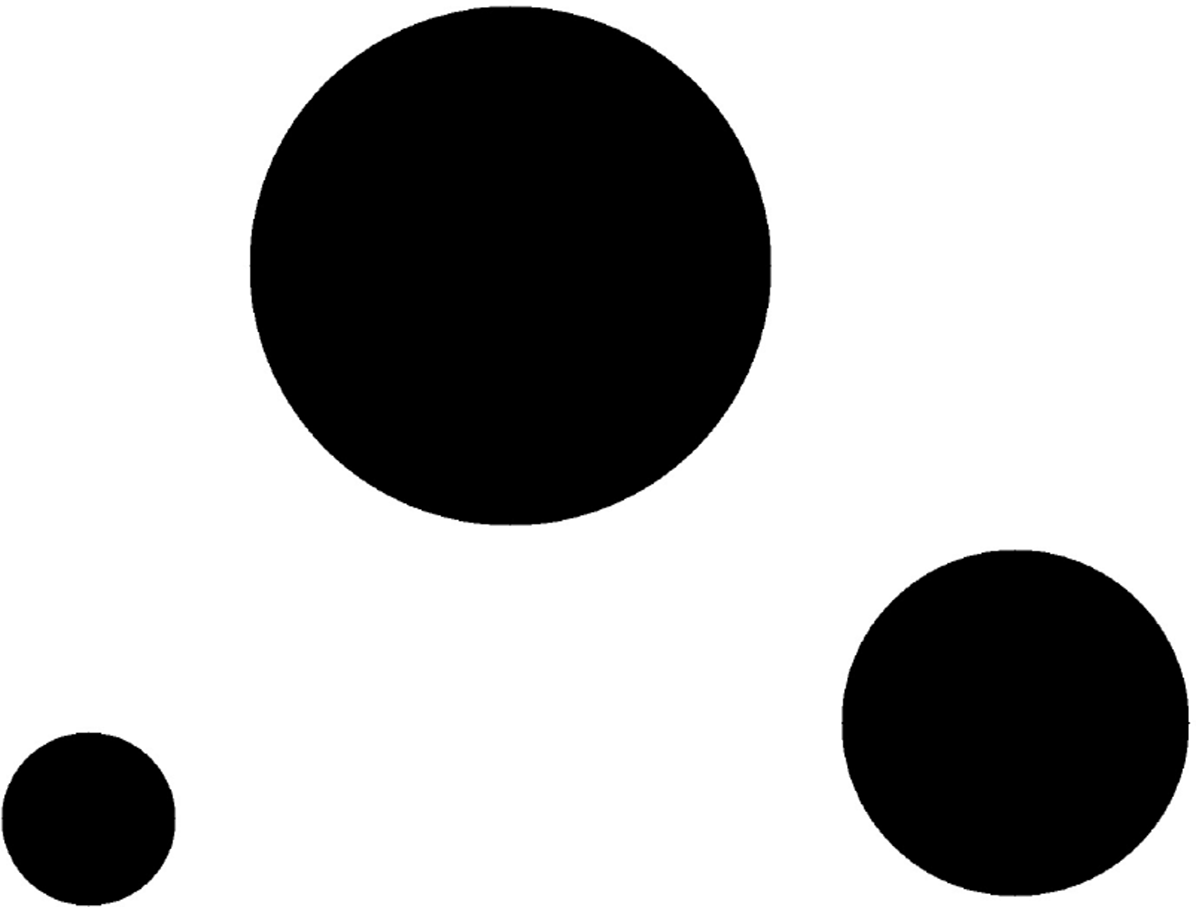
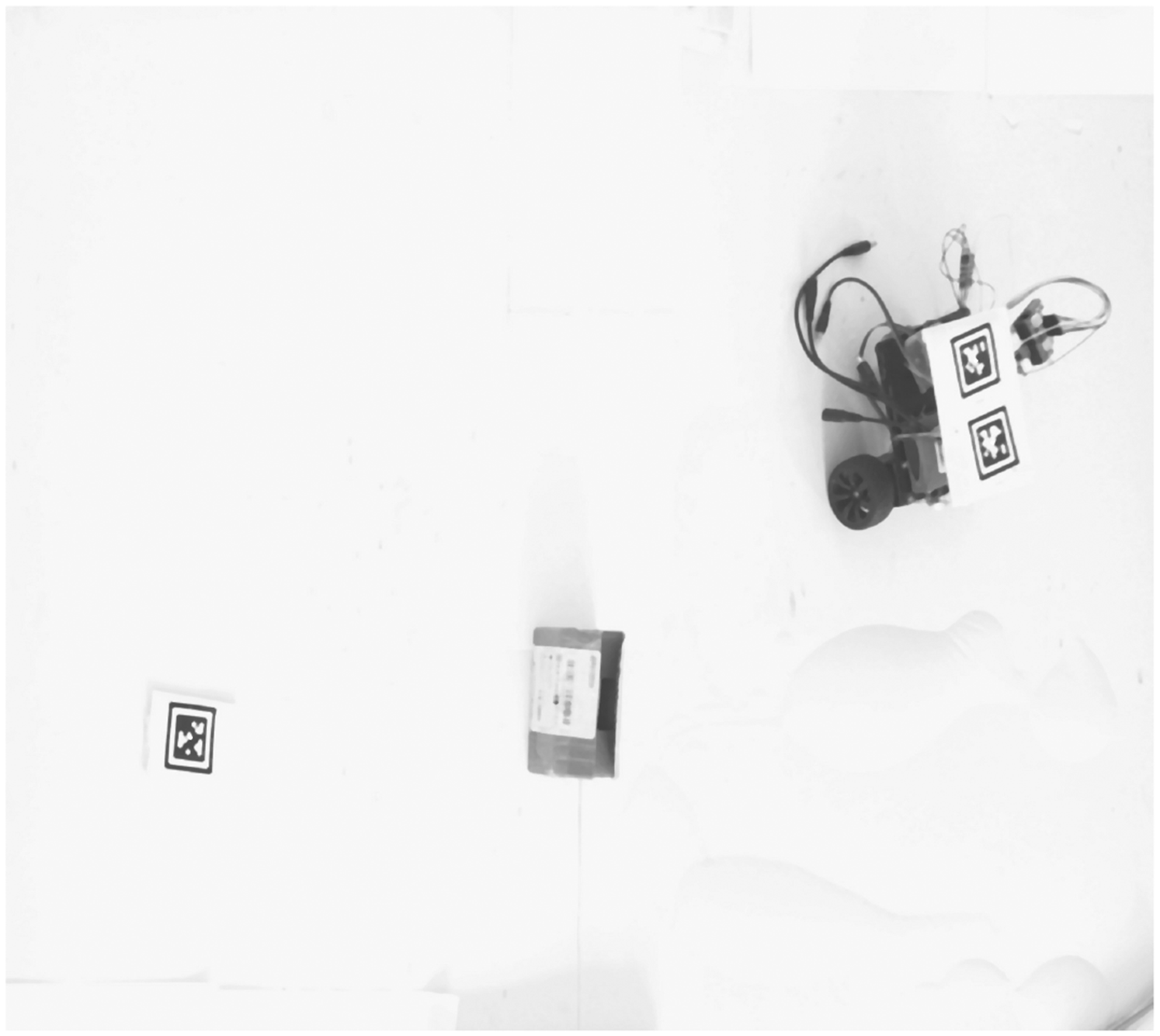
For the unknown obstacles, such as the box in Figure 11, this paper obtains the location and size information by image processing technology. Firstly, median filtering is used to remove the noise points and ensure the edge image. The effect is shown in Figure 12.

Images with unknown obstacles.
Images after median filtering.
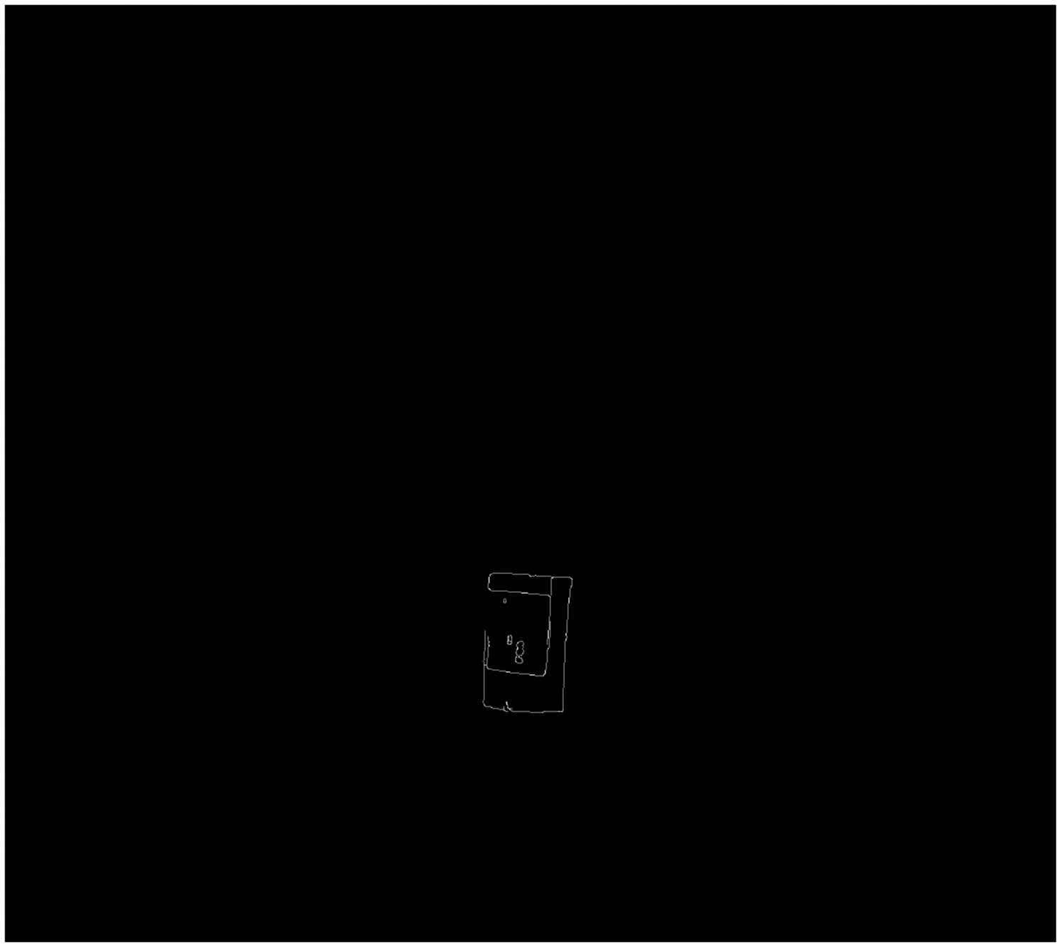
Then the edge of the image after median filtering is extracted. Canny operator is used as edge extraction. The algorithm uses two different thresholds to detect strong edge and weak edge, and when the weak edge and strong edge are connected, the weak edge is included in the output image, which can well suppress noise. The effect is shown in Figure 13. It can be seen that AGV, Apriltag and obstacle contours are well extracted after Canny operation.

Images after Canny operation.
As shown in Figure 14, the unknown obstacles need to be removed in the form of mask, because the contours of AGV and Apriltag are known information. Then morphological dilation and morphological closure are performed on the edge image which removes the known information. The purpose is to expand the area of the obstacle and fill the small grooves in the defect image while removing some edge stray points. The effect is shown in Figure 15.
Images for removing known obstacles and car contours.

Image after morphological operation.
Finally, all the obstacle information is integrated to form a binary map, as shown in Figure 16. The unknown obstacle area is represented by a rectangle, and the known obstacle area is represented by a circle. The binary map obtained here will be used as the input map of the path planning algorithm.

Binary Map images after image processing.
Path planning algorithm
There are many path planning algorithms, such as ant colony algorithm, genetic algorithm, A* algorithm etc. As the most effective direct search method for solving the shortest path in a static road network, A* is chosen to plan the path. At the same time, in order to verify the expansibility of the proposed method, other path planning algorithms will also be used for experiments.
A* algorithm
45
is a very common path finding and graph traversal algorithm, which has good performance and accuracy. The A* algorithm needs to search nodes in the map, and set the appropriate heuristic function to guide. By evaluating the generation value of each node, the next best node that needs to be expanded is obtained, until the final target point is reached. The cost function is expressed as:

The position of the center coordinates of the two rounds of AGV is set as the starting point of the path planning, and the target point is set as the end point. The binary map obtained by 3.2 is treated as the input map of the A* algorithm. The effect is shown in Figure 17. It can be seen that the algorithm can not only complete the path planning task well, but also label the position coordinates of each node.

A* algorithm for path planning.
With the continuous expansion of binary map, the time consumed by A* algorithm will increase. To solve this problem, the global map compression method for planning is adopted in this paper. The effect of this method is shown in the Figure 18 and Table 3.

Processing results of A* algorithm at different rates.
Time consuming of A* algorithm at different rates.
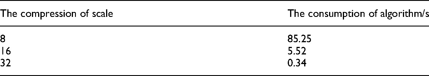
The time spent by A * algorithm is shown in Table 3. When the map is compressed to 8 times, 16 times and 32 times of the original map, the consumption of this algorithm is 85.25 s, 5.5 s and 0.34 s, respectively. This can prove that this method can greatly reduce the time consumed by the computer in path planning. In terms of driving accuracy, the path planned by this method can ensure the AGV to reach the destination from the starting point. As shown in Figure 18, the position coordinates planned by Figure 18 (c) with a reduction of 16 times and Figure 18 (b) with a reduction of 8 times are basically the same. And the position coordinates planned by Figure 18 (d) with a reduction of 32 times are slightly interfered with the obstacles only in oblique planning compared with Figure 18 (b). This problem can be solved by appropriately expanding the non-driving area to expand the safe driving range of AGV. Consequently, this method can shorten the path planning time under the premise of ensuring that AGV completes the driving task, which greatly improves the practicability of the proposed method.
AGV control algorithm under global vision
AGV steering adjustment and motion correction
According to 3.3, the starting point of path planning is the two-wheel center of AGV, and 3.2.1, the coordinate position and orientation angle of AGV are known. The A* algorithm has recorded the coordinate information of each path node in the realization of path planning, and thus the slope of each path driving section can be calculated. By continuously comparing the current position information and path position information of AGV, the AGV can be controlled to drive according to the specified path.
AGV steering adjustment
The AGV steering adjustment method is shown in Eq. (13), where is expressed as the driving path angle and the current angle of the AGV, and 

AGV steering adjustment diagram.
AGV moving correction
When the AGV completes the steering adjustment, the direction line and the driving path line of the AGV overlap. If the two-wheel skidding is not considered, at this time, only the AGV needs to keep straight to reach the node of the next planning path. The Euclidean distance between the AGV and the node of the planning path is calculated by Eq. (12), and the AGV stop condition is shown in Eq. (14):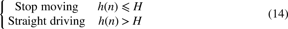
Through Eq. (14), it can be judged whether
In the actual operation process, when the AGV moves, there are different degrees of skidding in the two wheels. If the AGV is controlled straightly, it will make the AGV deviate from the planned path. In order to ensure the accuracy of AGV movement, it is necessary to use the rectification algorithm to control the AGV to walk according to the original planned path. The principle is shown in Figure 20.

AGV correction schematic diagram.
In Figure 20, the orientation of AGV coincides with the target path. In the straight process, assuming that the right wheel of AGV slips more seriously than the left wheel, the actual walking distance of the left wheel will be more than that of the right wheel, which makes the AGV deviate from the right. The deviation distance can be calculated by Eq. (15), where the coordinates of point A, B and C are
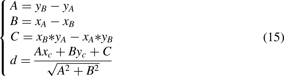
The absolute value of d is expressed as the vertical distance between the AGV center and the planning path, and the positive and negative of d is expressed as whether the AGV needs to correct the deviation to the left or the right. When the absolute value of d exceeds the set value, the master control computer will send correction instructions to the AGV control board, and control the direction and distance of AGV correction according to the value of d.
The correction method of AGV is shown in Figure 21. When the AGV is located on the right side of the target path, the AGV first rotates

AGV correction diagram.
AGV ultrasonic obstacle avoidance
When the AGV completes the path planning, the AGV needs to stop moving if it encounters a sudden situation or a moving object during the planned path, and different processing methods are performed according to different situations. This paper will be divided into two categories of emergencies, one is a short stay blocking, such as pedestrians, mobile devices through, etc. The second category is a long stay blocking, such as cargo loading and unloading on the original planning path.
For the first kind of problem, this paper adopts the way of AGV stop moving and waiting, and for the second kind of obstacle residence time is longer, this paper adopts the way of replanning the path. When the HC-HR04 ultrasonic module in front of the AGV detects that an object stays in front of the AGV during driving, the AGV controller sends a new obstacle request to the master control computer and controls the AGV to stop moving. After a short wait, the AGV again detects whether there is an obstacle in front of the AGV. If not, the AGV continues to follow the original planned path. If still exists, the AGV controller sends a replanning path request to the master control computer, and controls the AGV to follow the new planned path.
When AGV is planning the path according to Figure 17, the original path of AGV is artificially added with obstacle. AGV requests to re-plan the path, and the new path is shown in Figure 22. This proves that the ultrasonic module can solve the problems caused by sudden accidents, which greatly improves the flexibility and practicability of AGV driving under global vision.
Requests re-planning path.
Verification and analysis of AGV guidance technology based on global vision
In order to verify the feasibility and reliability of the proposed method, an AGV is built with the hardware described in section 2.3, as shown in Figure 23.

AGV physical map.
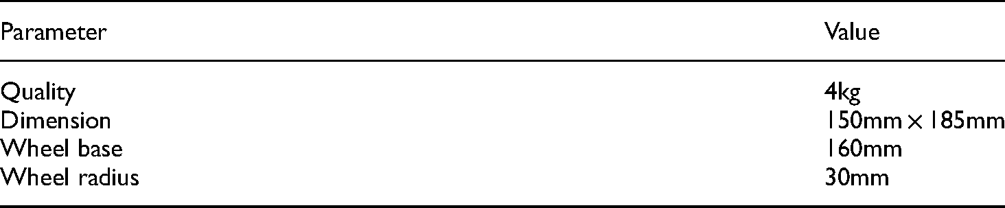
The basic parameters of the vehicle are shown in Table 4.
Basic parameters of AGV.
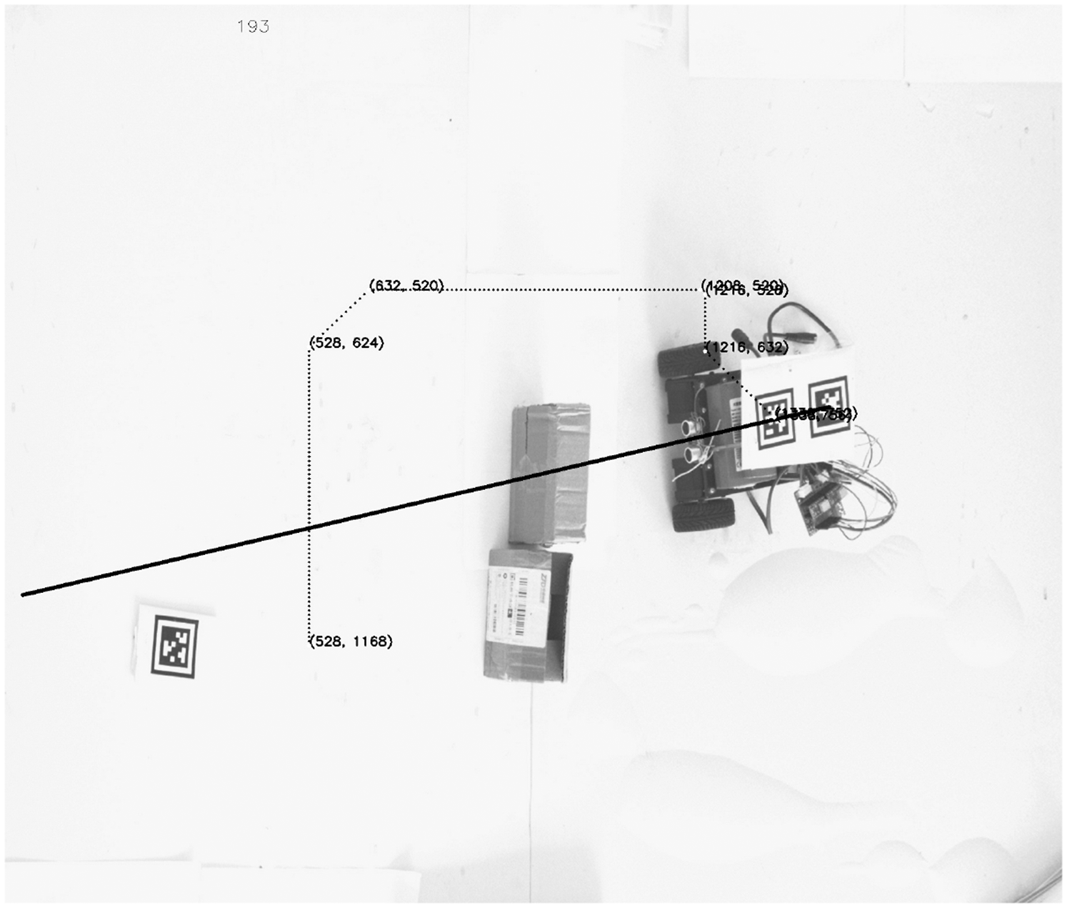
In this paper, different layouts and driving emergencies of different factories are simulated by placing different obstacle positions and artificially moving AGV. The maximum deviation distance, parking accuracy and average moving speed are recorded respectively. The allowable AGV angle error value is set to be positive and negative 2 degrees. When the AGV is less than 30 pixels from the target point, it is regarded as the destination. When the deviation distance is greater than 40 pixels, it is judged as the current AGV deviates from the driving path. The effect is shown in Figure 24, where the dashed line represents the planned path of A* algorithm, the solid line represents the actual walking path of AGV, and the boxes and black objects represent obstacles. The test results are shown in Table 5.

AGV movement diagram under different obstacle environments.
Test parameters of different obstacle types.

It can be seen from Figure 24 that the guidance technology proposed in this paper can not only complete the path planning task in different obstacle environments, but also respond well to emergencies in the driving process, and finally control the AGV to reach the target position. This experiment strongly proves the feasibility and reliability of the guidance technology proposed in this paper.
It can be seen from Table 5 that the average maximum deviation distance in the normal test is 37.8 pixels (6.3 mm), and the average stop accuracy is 24.6 pixels (4 mm). The average moving speed is 0.35 m/s at the fastest and 0.18 m/s at the slowest Due to the influence of transmission speed and image processing speed, the average moving speed of the guidance technology proposed in this paper is low. However, with the improvement of technology and the replacement of hardware equipment, there is still much room for the improvement of the moving speed of the guidance technology. The maximum deviation value and stop accuracy in the experiment are within the specified range, and with the increase of camera pixel value, AGV moving accuracy will also be greatly improved.
To verify the flexibility of the technology, new obstacles are added to the driving path when AGV is running along the planned path. The result is shown in Figure 25.

Add new obstacles when AGV is running.
As shown in Figure 25, the green box in the figure is the obstacle placed at the beginning. The green point is the starting point of the first path planning, and the planned route is A. Then, a new obstacle, namely the red box, is added when AGV is moving. AGV recognize the obstacle at the red point and re-plans the path to obtain the new route B. AGV continues to drive along the new route and finally reaches its destination. This experiment well proves the flexibility of the proposed method to adapt to the dynamic environment.
In addition, the proposed method in this paper also has strong expansibility. That is, different path planning algorithms can be used according to different needs in different situations. For example, D * algorithm can be used in dynamic planning, and rapidly-exploring random tree (RRT) * algorithm can be used in complex environments. In the experimental part of this paper, RRT*-Smart is used to replace A * algorithm for path planning to verify expansibility. The result is shown in Figure 26.
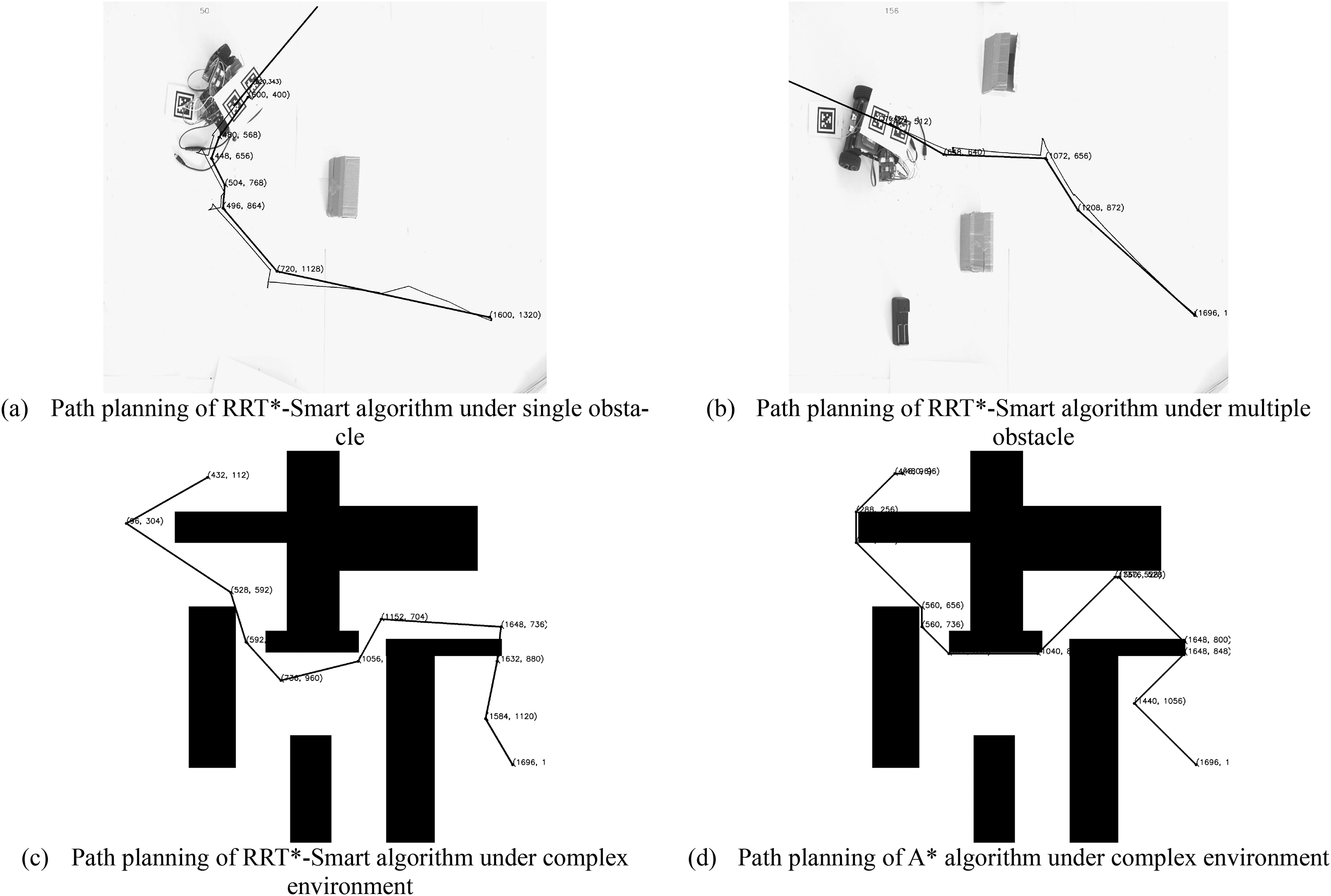
RRT*-smart algorithm for planning path.
As shown in Figure 26(a) and Figure 26(b), the RRT algorithm can well complete the path planning task and make AGV reach the target point, whether in single obstacle or multiple obstacles. At the same time, due to the strong randomness of the algorithm, the algorithm is not very ideal in a simple environment. However, the comparison between Figure 26(c) and Figure 26(d) shows that this algorithm performs better in complex environment than the A * algorithm for fewer break points. This also proves that different algorithms have different advantages in different environments, which indicates that a highly extensible guidance technology is crucial for AGV.
In the experiment, this paper uses a single camera to verify the feasibility of the algorithm. In fact, the guidance technology proposed in this paper can also be applied to multi-camera control AGV movement. Through multi-camera stitching technology, the image range can be greatly improved, and the AGV driving area in this paper can be effectively improved, so that the guidance technology has better practicability and adaptability.
Conclusion
This paper presents an AGV trackless guidance technology based on global vision. Firstly, the moving area of AGV is obtained by image perspective transformation, and then the position information of AGV and its obstacles is determined by positioning technology and image processing technology. Then the information is synthesized into binary map and used as the input map of A* algorithm to plan the AGV path. Finally, the AGV is controlled to travel according to the planned path by wireless communication until the AGV reaches the set position.
The guidance technology designed in this paper is verified in the experimental section. The experimental results show that the method can plan the path intelligently according to the surrounding environment of AGV, and adjust the AGV walking path timely and automatically in case of unexpected situations. It has high flexibility, reliability, expansibility and mobile accuracy, and has obvious advantages over existing guidance technologies in terms of operating costs.
Footnotes
Declaration of competing interest
The authors declare that they have no known competing financial interests or personal relationships that could have appeared to influence the work reported in this paper.
Declaration of conflicting interests
The author(s) declared no potential conflicts of interest with respect to the research, authorship, and/or publication of this article.
Funding
The author(s) disclosed receipt of the following financial support for the research, authorship, and/or publication of this article: This work is financially supported by Key R&D Project of Zhejiang Province (2020C01084, 2021C01071), Longgang Research Institute Project of Zhejiang Sci-tech University (LGYJY2021004) and Zhejiang Provincial General Scientific Research Projects Fund of China (Y202148127).