
Abstract
The purpose of this study was to save manpower and reduce costs on water quality measurement in cage culture. An unmanned aerial vehicle system was applied to locate the target net cage and detect the water quality and temperature in the desired cage automatically. This paper presents the use of image recognition and deep learning to find a predefined target location of cage aquaculture. The whole drone control and image recognition process was based on an onboard computer and was successfully realized in an actual environment. When the drone approached the net cage, image recognition was utilized to fix the position of the unmanned aerial vehicle on the net cage and drop a sensor to check the water quality. The proposed system could improve conventional manned measurement methods and reduce the costs of cage culture.
Introduction
Marine fish farming has grown to be a major industry in many regions of the world, producing approximately 6.6 million tons of fish per year. 1 Sea-cage fish farms are the most commonly used standard production units in the marine aquaculture industry. Cage farms are positioned to utilize natural currents, which provide the fish with a free flow of water with oxygen and other appropriate natural conditions. Two major types of cages are surface-based cages and submerged cages. Although cage aquaculture has many benefits, there are challenges to be solved. These include the overcrowding of fish in cages, and a relatively high incidence of disease that can spread rapidly; there can be localized poor water quality, such as low dissolved oxygen, in and around cages; caged fish do not have access to natural food, so a nutritionally complete diet is required; accumulation of unused feed and excreta will lead to water pollution as well as eutrophication. 2 Submerged cages may reduce some of these problems. 3 Despite these problems, all cages need a monitoring system and a detection device for environmental conditions. Nowadays, the wireless internet of things (IoT) sensors are desired for a variety of such applications as agriculture, aquaculture, and security. Specifically, water quality monitoring IoT sensors are already applied to cage aquaculture. 4 However, wireless and low-power systems are needed for sea-cage fish farms. For long-range data transmission, the LoRa wireless system is mostly used. LoRa consumes low power, but the range is only about 1 km with 95% data accuracy. Longer range transmission requires a higher power battery. In addition to the battery, each cage needs its sensors. The cost of sensors and batteries for a large farm is high. The objective of this study is to apply an unmanned aerial vehicle (UAV) to automatically measure the water quality in the net cage. Only one set of sensor and battery is needed in the UAV. This study is expected to save manpower, reduce the cost of sensor devices, and further achieve accurate data of the cage culture environment.
The early applications of UAVs were mainly military reconnaissance missions or attack activities.5–7 In recent years, UAVs have been mainly used for civilian applications, and they have been developed rapidly and extensively. UAVs have now become an important tool for commercial, government, and consumer applications. 8 They can be used for disaster relief as well as in the agriculture and fishery industries, as used in this study. Among these applications, UAVs with cameras are the most commonly used devices. This study integrated image recognition and deep learning into a UAV to recognize target images that could also be used for UAV position control. There are three types of UAVs, namely fixed-wing drones, helicopters, and multicopters. A multicopter was used in this study. Although a multicopter is not as fast as a fixed-wing aircraft, it is more flexible than a helicopter, as it can move in any direction and has strong disturbance resistance, which the other two do not have. 9 A multicopter UAV has a simple structure and a low cost, which is quite suitable for aquaculture. At present, most of the common multi-axis drones have four axes. In this study, in consideration of the wind on the sea and the weight of the drone, we used a six-axis UAV which had strong wind resistance and a high load capacity. The UAV was also equipped with an RTK (real-time kinematic) four-galaxy positioning chip that was more accurate than GPS, 10 thus making the UAV positioning more accurate. The onboard computer gave instructions to control a Pixhawk flight control board. As GPS may be disturbed due to weather factors or environmental influences, image recognition was needed to correct the position of the drone. This study used a modified YOLOv4-tiny (you only look once version 4-tiny) detection system for image recognition. The proposed neural network structure reduced the computational complexity and improved the frame rate (frames per second [FPS]).
With the rapid and versatile development of UAVs, they can be applied to people's lives to reduce labor costs and improve efficiency. Unmanned vehicles have been utilized in many applications,11–17 such as failed solar panel detection, octopus drift fishing, geological and environmental applications, parcel delivery, and pollution monitoring. In many applications, the drone flies to a location to collect data, and the navigation is achieved either through human operators or autonomously. This study used automatic navigation. Current approaches to image recognition make essential use of machine learning methods. Deep learning belongs to a branch of machine learning and artificial intelligence (AI) and was developed by simulating the operation of human neural networks. First, it uses an algorithm and a large amount of data for training to generate a model, which is then used to make predictions. Since the advent of deep learning, it has become a part of various leading systems, especially in computer vision and speech recognition. Experiments on general test data sets, such as ImageNet 18 and Cifar10 19 in image recognition, have proved that deep learning can improve the accuracy of recognition. Hardware advancements are also an important factor for the increased attention paid to deep learning. The emergence of high-performance graphics processors has greatly improved the speed of numerical and matrix operations and has significantly shortened the execution time needed for machine learning algorithms. Common deep learning network architectures include the support vector machine (SVM), 20 recurrent neural network (RNN), 21 and convolutional neural network (CNN). Liu et al. 22 used the scale-invariant feature transform (SIFT) algorithm to locate the objects. Image cropping was applied to get the object region from image features. It was then put into the CNN object recognition system and could recognize specific objects with 70% accuracy. Zhao et al. 23 improved the Libra R-CNN and solved the difficult-to-distinguish target in target detection problems. The experiment was carried out on the MS COCO 2017 and traffic sign datasets. The improved Libra R-CNN is 3 percentage points better than the unimproved Libra R-CNN's mean average precision (mAP). In 2016, Redmon et al. proposed the You Only Look Once algorithm (YOLO), which uses one-stage real-time object recognition. YOLO is faster than R-CNN, and at 57.9%, its mAP is better than those of R-CNN and fast R-CNN. 24 The YOLOv4-tiny algorithm 25 used in this study was proposed in 2020. It is based on YOLOv4 26 but has a smaller size and uses less computing time. YOLOv4-tiny is suitable for vehicles that move quickly, such as the drone used in this study. In recent years, the manpower and costs of aquaculture have been greatly reduced, but the time needed to detect water quality has been prolonged. For this paper, the main contributions are as follows: (1) this study applies a UAV to replace the manpower needed for water quality measurements, which can reduce the detection time; (2) different types of cages can be located by the improved image recognition networks, the UAV is then guided to the desired cage location by this image; (3) sensor devices for each cage are not required, and the costs of aquaculture can be further reduced.
System description
The hardware structure was mainly divided into two parts. The first part was the ground station, which contained a computer, an RC (radio control) system, and an RTK base station. The second part was the drone, which consisted of a Pixhawk flight control board, a GPS module, a radio telemetry module, an RC receiver, a camera, a gimbal, and an onboard computer. The signal flowchart is shown in Figure 1. Radio telemetry was used to communicate between the drone and the ground station. The flight information of the UAV was transmitted back to the ground station through radio telemetry. The computer was connected through a network to the onboard computer to remotely control the UAV's operations.
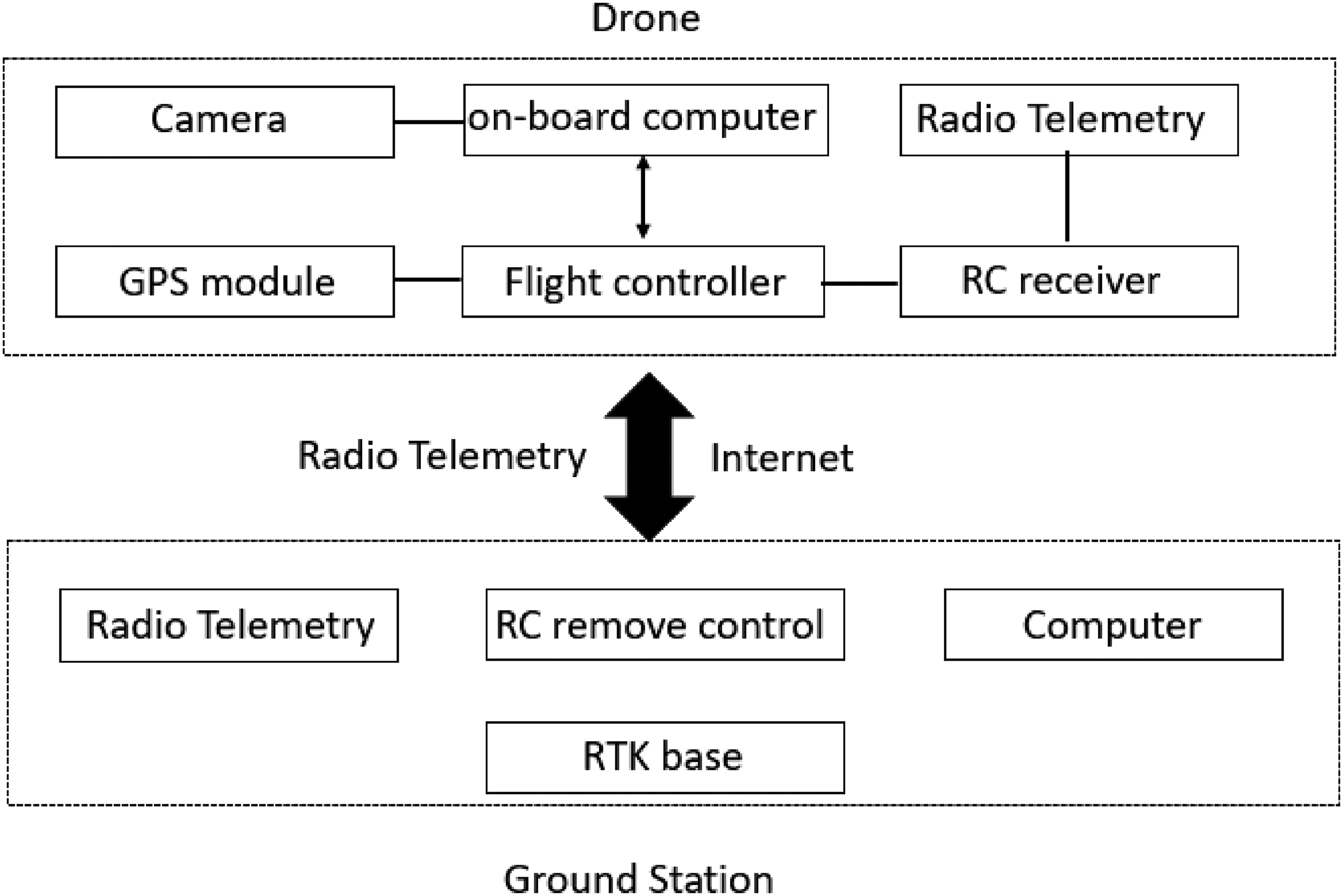
Signal flowchart of the overall drone hardware.
There are many types of UAVs in the world today, but none of them could be used to carry out the object of this research; therefore, this study used a self-made UAV that contained the required equipment. Because the UAV had high equipment requirements and would encounter strong winds at sea, a six-axis drone was used, which can carry more equipment to overcome strong winds and stabilize the flight. Figure 2 is the main body of the UAV.

UAV main body. (a) Front view of the UAV. (b) Rear view of the UAV. (c) Top view of the UAV.
The UAV performed its mission on the sea, about 1 km away from the coast. Image recognition was used to detect and locate the net cage target. As the mission required complex computations, UAV control, and flight status monitoring of the UAV, it required a powerful processor. An NVIDIA Jetson Xavier NX 27 was chosen as the onboard computer. The NVIDIA Jetson Xavier NX has the advantages of being small in size, being lightweight, and having high-performance capabilities. The Jetson Xavier NX can provide up to 21 trillion operations, which is most suitable for supporting high-performance computing and operating in embedded system and it can execute multiple modern neural networks in parallel. The operating system used Linux and Python, which are both compatible with the Jetson Xavier NX. Several peripheral devices were also connected to realize UAV automation. The camera used in this study was an SJCAM SJ5000X, which has an adjustable angle of view (from 70° to 140°) and allows streaming when performing image recognition, which allowed the target to be more clearly detected when performing image recognition. The gimbal was a Tarot T2-2D, which used a two-axis gimbal to accurately lock the camera and maintain high stability. The built-in independent Inertial Measurement Unit (IMU) could accurately control the gimbal posture and integrate the gimbal and servo module. Giving Pulse-Width Modulation (PWM) signal through the process program to control the gimbal pitch angle, the camera could recognize the desired target, and then the flight controller could fix the UAV position.
In this study, a Pixhawk 4 28 control board was used to assist the UAV's flight. The Pixhark had a built-in accelerometer, a barometer, a gyroscope, a compass, and other sensors. The attitude of the UAV could be calculated by the speed changes of the three axes obtained by the accelerometer. The gyroscope could measure the speed, and the barometer could get the flight altitude. The Pixhawk 4's microcontroller had 2 MB flash memory and 512 KB RAM. The high-performance and low-noise IMU on the board was designed for stable applications. The vibration isolation device allowed more accurate readings so that the UAV could achieve better overall flight performance. To maintain the UAV at a certain altitude, a barometer was set in the flight controller to calculate the current altitude of the UAV. However, barometers can cause errors due to wind, resulting in unstable UAV altitudes; therefore, GPS was used to calculate the altitude of the UAV and reduce the error. At the same time, the use of GPS provided better UAV positioning and flight stability. The GPS module is neo-m8n, which can only receive three Global Navigation Satellite System (GNSS) signals at the same time (GPS, Galileo, and BeiDou). In response to the high accuracy requirements of flying at sea in this research, we used an F9P-RTK GPS module, which can receive four GNSS signals (GPS, GLONASS, Galileo, and BeiDou). It has a multi-band RTK receiver with a fast convergence time, reliable performance, and an error accuracy of within 1 m, which allowed our UAV to travel near the target. The error could therefore be greatly reduced, while the height and stability of the UAV could be greatly improved. The F9P-RTK chip on the UAV is shown in Figure 3, and the RTK base station is shown in Figure 4.
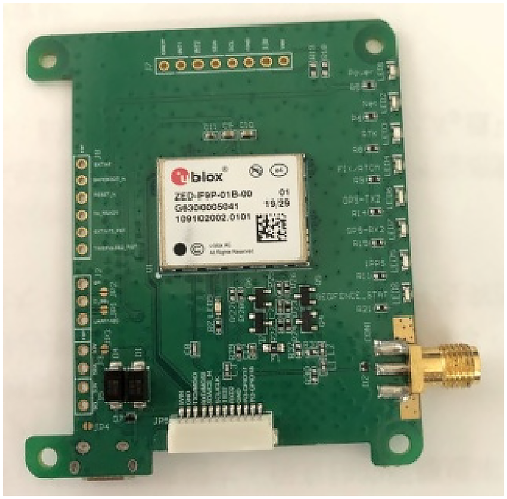
F9P-RTK.

RTK base station.
To obtain the water quality and temperature data of the net cage, a dual-motor reel was designed, as shown in Figure 5. Because the sensor wire was thick and the surface had an insulator, the friction force would be insufficient to pull up or drop the sensor using a single motor. Therefore, two motors were clamped to the sensor wire to increase the friction and allow the sensor to be pulled up or dropped down.

Dual-motor reel system.
The image data of the target net cage were collected and used as the learning data for the YOLOv4-tiny network. After deep learning, the weights were put into the YOLOv4-tiny network. The onboard computer executed the YOLOv4-tiny network for image recognition and commanded the Pixhawk controller to maneuver the UAV to the target net cage position. After the GPS information of the target net cage was transmitted to the onboard computer, the drone could lift off and move toward the target net cage, and then start running YOLOv4-tiny. When the target was recognized, the UAV would reduce its forward speed, and the gimbal would adjust its angle. The camera would gradually tilt down until the lens faced directly downward, to keep the image of the net cage in the frame. Afterward, the UAV position could be adjusted to keep the net cage image at the center of the camera screen by adjusting the UAV's left and right movement. After the correction was completed, the sensor would be placed at a low altitude and the dual-motor reel system signal would be given. After the task was completed, it would immediately return to the starting point. System control and image detection were all performed through the Jetson Xavier NX onboard computer automatically. The flow chart of the UAV mission is shown in Figure 6.
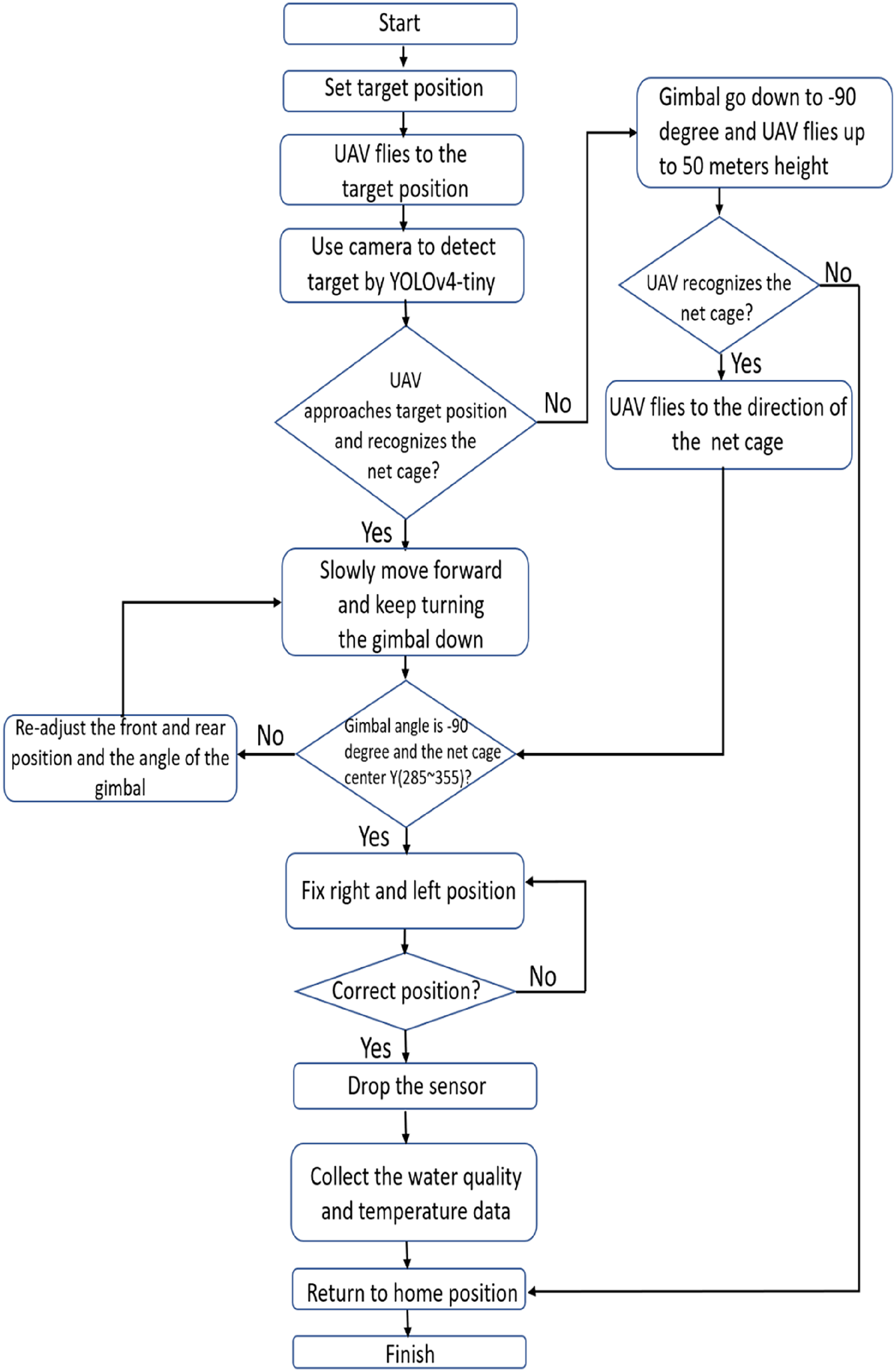
Drone task flowchart.
Image recognition
Image recognition was an important part of this study, and deep learning and CNNs were used to obtain the required training data weights. Then, YOLOv4-tiny was used for image recognition, and the position of the UAV was adjusted through image recognition. The flow chart of the deep learning procedure used in this study is shown in Figure 7.

Deep learning flowchart.
Nowadays, AI has developed rapidly, and image recognition has gradually entered people's lives. The field of image recognition represents the most vigorous development of deep learning in recent years and can be seen in areas such as smart home devices, self-driving systems, production of defect detection, security monitoring, and medical imaging, which are all closely related to deep learning image recognition technology. Although the image recognition rate for ordinary pictures is equivalent to that of humans, the recognition accuracy of dynamic images is still not as accurate. In response, various algorithms have been developed and can be mainly divided into two categories:
Two-stage algorithms: including R-CNN and fast R-CNN, etc., in which the prediction box is carried out in the first stage and classification is carried out in the second stage. Although the accuracy is high, the calculation amount is too large for real-time identification. One-stage algorithms: including SSD
29
and the YOLO series, etc., which address the problem of the excessive calculation requirements of the two-stage algorithms. In one-stage algorithms, the prediction box and classification are generated at the same time, thus reducing the number of calculations and making them suitable for real-time identification.
The YOLOv4-tiny algorithm used in this study is a one-stage algorithm. In past years, One-stage accuracy was not as good as Two-stage, but it has been improved recently.
Object detection is an image recognition technique. In this study, target recognition was divided into the three steps of image classification, target location, and target recognition, as shown in Figures 8 to 10, respectively. Figure 11 shows the bounding box and center information. Image classification involves predicting the category of an object in an image. There was only one category for the target in this study, and no special classification was required. Target positioning refers to identifying the location of one or more objects in an image and drawing a bounding box around their range. Target recognition combines these two tasks and locates and classifies one or more objects in the image, thus providing the name and confidence index of the target. In this study, the bounding box (X, Y, W, and H) of the recognition target was used to control the UAV positioning to the target net cage.

Image classification.

Target location.

Target recognition.

Target recognition, bounding box, and target center.
In 2015, YOLO was proposed, which is the first one-stage object detection algorithm and the first object detection algorithm that can achieve real-time detection; however, fast R-CNN still has slightly better detection accuracy. YOLOv2 30 was presented as an improved version in 2016. It has an efficient network structure that uses Darknet-19 as the main network. The calculation procedure is only 1/5 of VGG-16 (the most famous deep learning model of the Visual Geometry Group), and YOLOv2 does not contain a fully connected layer, which means that it has no limit on the size of the input image. The recognition accuracy and recognition speed can be adjusted by adjusting the size of the input image. YOLOv3 31 was launched in 2018, and its most important feature was the change of the main body network. A new backbone (Darknet53) was used in YOLOv3, and multi-level feature maps were used for detection. In April 2020, Bochkovskiy et al. 26 launched YOLOv4, in which the main structure was changed to CSPDarknet53. The excitation function and loss function were improved, as were the accuracy and calculation speed. In June 2020, YOLOv4-tiny was developed to simplify the structure of YOLOv4 and increase the calculation speed. This study used YOLOv4-tiny because it can perform real-time image recognition and has good accuracy.
YOLOv4-tiny was proposed on the basis of YOLOv4. YOLOv4-tiny only uses two feature layers for classification and regression prediction, which simplifies some network structures and greatly improves the speed. While YOLOv4 has a total of about 60 million parameters, YOLOv4-Tiny has only 6 million parameters, which makes it suitable for applications in mobile and embedded devices. Its performance on the COCO dataset, whether it is AP (average precision) or FPS performance, is a huge improvement compared to YOLOv3-tiny, Pelee, 32 and CSP, 33 as shown in Figure 12. 34

YOLOv4-tiny on the MS COCO.
The network layer of YOLOv4 has as many as 162 layers, regardless of size and computational complexity (its billion floating-point operations [BFLOPS] are greater than those of YOLOv4-tiny). When real-time image recognition is performed, the large number of network layers will cause a delay. YOLOv4-tiny has only 38 layers, which is nearly 10 layers more than YOLOv3-tiny's 24 layers, but the accuracy and FPS are better than YOLOv3-tiny. The YOLOv4-tiny network structure is shown in Figure 13.

YOLOv4-tiny structure.
YOLOv4-tiny uses the CSPDarknet53-tiny 35 network as the backbone network instead of the CSPDarknet53 used in YOLOv4. The CSPDarknet53-tiny network uses the CSPBlock module network, as shown in Figure 14. Instead of using the ResBlock module in the residual network in the cross-stage part, the CSPBlock module divides the feature map into two parts and combines the two parts through cross-stage residuals. This allows the gradient flow to propagate the network path in two different directions to increase the correlation difference among the gradient information. The CSPBlock module can enhance the learning ability of the convolutional network better than the ResBlock module. Although this increases the calculation amount by 10–20%, it improves the accuracy. To reduce the calculation amount, it eliminates the modules with higher calculation amounts in the CSPBlock module, which improves the accuracy of YOLOv4-tiny and reduces the number of calculations.

YOLOv4-tiny CSPBlock.
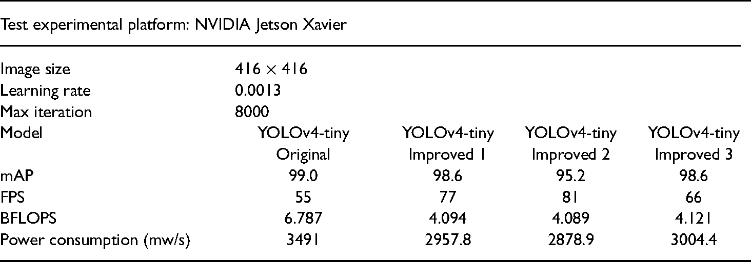
Before performing image recognition, it was necessary to collect enough data and obtain proper weights for later image recognition. A total of 3202 images were collected in this study, including negative data. According to the recommendations of the YOLO network, all the image data were divided into 1841 training data items and 461 validation data items (a 4:1 ratio). These data were labeled by the freely available LabelImg tool as the bounding box and class name of the net cage. In order to improve the accuracy of recognition, images of the net cage were taken at different angles, sizes, and types of focus. These data helped to improve the training results and reduce the occurrence of unrecognized or incorrectly recognized rates. Figure 15 shows part of the training dataset. The training parameters and graphics processor are shown in Tables 1 and 2.

Net cage training dataset. (a) TOP view of the net cage. (b) Top view from another angle of the net cage. (c) Overlook of the net cage. (d) Blurry net cage.
Graphics processor.

Training parameter setting.

YOLOv4-tiny improvements
In this study, YOLOv4-tiny was used for real-time image recognition. Although YOLOv4-tiny is mainly used for mobile or compact computers, it still consumes a lot of time and power in image recognition. We improved its structure so that it could be used in UAVs to save power without reducing the accuracy of recognition. The following are the categories we want to improve and then compare with the original YOLOv4-tiny:
mean average precision (mAP) Billion floating-point operations (BFLOPS) frames per second (FPS) electric energy consumption.
The mAP is a common measurement method in target detection problems. Semantic and even instance-based segmentation detection methods need to predict the target position in the image, and mAP is used at this time. For each application, it is necessary to find a metric to compare the performance of the model. However, before explaining mAP, we must also know the precision, recall, and AP. Table 3 is the so-called confusion matrix. The first True and False represent whether the result of the prediction itself is correct or incorrect, while the latter Positive and Negative represent the forward direction of the prediction.
Confusion matrix.

(1) Precision
The ratio of the predicted object to the target object is actually the target object. It can be known whether the result is accurate when the model predicts the target object.
(2) Recall
The actual target is also predicted to be the proportion of the target, and the ability of the model to find the target can be known. Through Table 3, we can get precision and recall.
(3) Average Precision
The AP can be obtained through precision and recall. In simple terms, the AP is the average value of the precision for each recall. If the image recognition targets are more than one category, the AP can be calculated for all classifications, and the average value can be used to get the mAP. Since there was only one category in this study, AP was equivalent to mAP.
(4) BFLOPS
BFLOPS refers to floating-point operations and is understood as a calculation amount. It can be used to measure the complexity of CNN algorithms or models. It describes how many BFLOPS are required for a certain convolution operation and is used to express the complexity of an algorithm model. The greater the BFLOPS is, the better the performance of the computing consumption will be.
(5) FPS
FPS refers to the number of frames per second, which is used to describe how many frames can be processed per second. In image recognition, the image is composed of pictures, and each picture is one frame. The higher the FPS in the model is, the more pictures can be processed per second. FPS was extremely important in this research because if the real-time image recognition FPS was not high enough, it would cause a delay, which would affect the UAV positioning correction.
YOLO image recognition has a multi-layer CNN that requires many calculations, and there will be high power consumption at this time. The UAV used in this study was powered by a LiPo battery. As the battery power was limited, power consumption was very important. The YOLOv4-tiny architecture is simplified compared to that of YOLOv4. Since the characteristics of the target identified in this research were simpler, only one category needed to be identified. Therefore, we could reduce the number of neural network layers in YOLOv4-tiny. In the case of counting and reducing the amount of BFLOPS, YOLOv4-tiny still has high accuracy and high FPS. From this goal, the improved structure of YOLOv4-tiny with three architectures was applied.
(1) YOLOv4-tiny Improved 1
YOLOv4-tiny Improved 1 is shown in Figure 16. There were a total of 37 layers of CNNs. The difference from the original structure is that part of filter 512 was deleted, and the YOLO output layer deleted filter 512 while adding filter 32 and filter 64 as convolutional layers. The YOLO output layer was the same as the original version, with 13 × 13 and 26 × 26 structures used to predict the detection target.
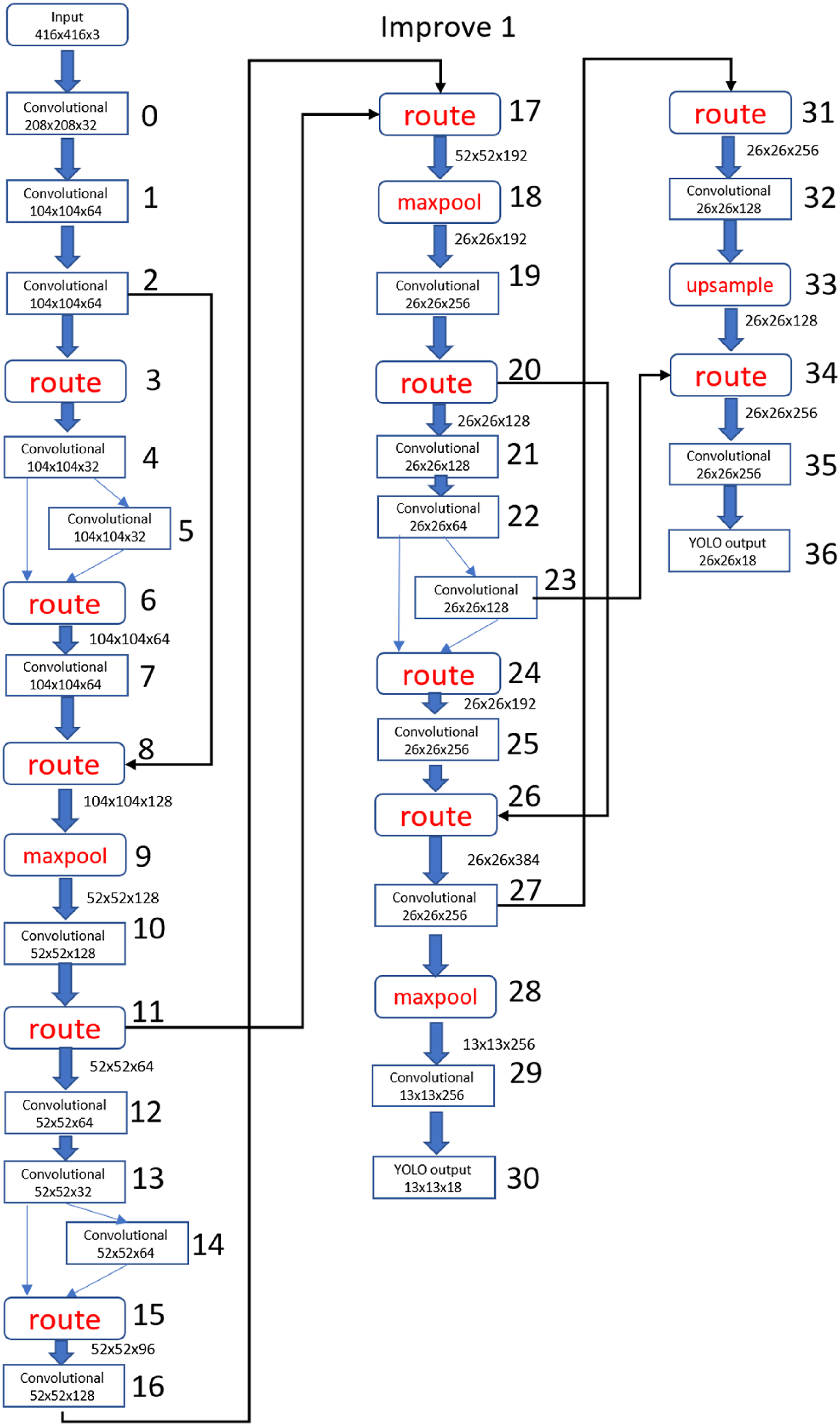
YOLOv4-tiny Improved 1 structure.
(2) YOLOv4-tiny Improved 2
As shown in Figure 17, there were a total of 38 layers of CNNs. The number of layers was the same as YOLO4-tiny, but its structure was similar to YOLOv4-tiny Improved 1. Part of filter 512 in the YOLO output layer was deleted, and filter 32 and filter 64 convolutional layers were added at the same time. The YOLO output layer had two 13 × 13 structures and one more maxpool layer.

YOLOv4-tiny Improved 2 structure.
(3) YOLOv4-tiny Improved 3
As shown in Figure 18, there were a total of 36 layers of CNNs. Compared with the original version and the above two improved models, the number of layers in YOLOv4-tiny Improved 3 was the smallest The biggest change in the CNN structure was that there were only two maxpool layers, and the final YOLO output layer was changed to two 26 × 26 structures.

YOLOv4-tiny Improved 3 structure.
Comparison of the improved structures
We used the same training times and data to compare and analyze the original YOLOv4-tiny model and the three improved models. The main reference indicators were mAP, FPS, BFLOPS, electric energy consumption, and target recognition accuracy.
(1) Improved mAP
Figure 19(a) to (d) show the mAP graphs of 8000 training iterations of the original YOLOv4-tiny, Improved 1, Improved 2, and Improved 3. It can be seen from the figure that there was only one category and the target characteristics of the net cage were simple, so the mAP had more than 95% accuracy.

Comparison of mAP. (a) Original YOLOv4-tiny mAP. (b) YOLOv4-tiny Improved 1 mAP. (c) YOLOv4-tiny Improved 2 mAP. (d) YOLOv4-tiny Improved 3 mAP.
(2) Improved FPS
Table 4 shows the FPS of the original YOLOv4-tiny, Improved 1, Improved 2, and Improved 3 algorithms when running on the onboard computer.
Filter comparison.

(3) Improved BFLOPS
Figure 20(a) to (d) show the calculated BFLOPS of the original YOLOv4-tiny, Improved 1, Improved 2, and Improved 3 when the onboard computer was running. The BFLOPS of each CNN layer was calculated separately and then added up to get the total BFLOPS. The total BFLOPS of the original YOLOv4-tiny, Improved 1, Improved 2, and Improved 3 algorithms were 6.787, 4.094, 4.089, and 4.121, respectively. Through the following pictures, we could find that the BFLOPS of Improved 1, Improved 2, and Improved 3 were less than that of the original YOLOv4-tiny algorithm because of the improvement in the neural network structure.

Comparison of BFLOPS. (a) YOLOv4-tiny BFLOPS. (b) YOLOv4-tiny Improved 1 BFLOPS. (c) YOLOv4-tiny Improved 2 BFLOPS. (d) YOLOv4-tiny Improved 3 BFLOPS.
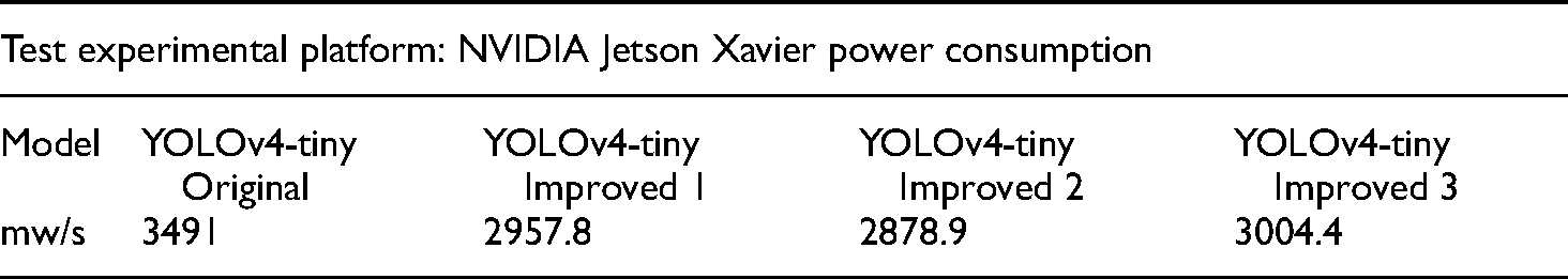
(4) Improved Electric Energy Consumption
The YOLOv4-tiny real-time image recognition requires a lot of computing power. An onboard computer was used on a UAV, and excessive power consumption would cause the battery power to drop too fast for image recognition. Table 5 shows the average power consumption per minute for YOLOv4-tiny, Improved 1, Improved 2, and Improved 3 when running on the onboard computer.
Comparison of electric energy consumption.
Control scheme
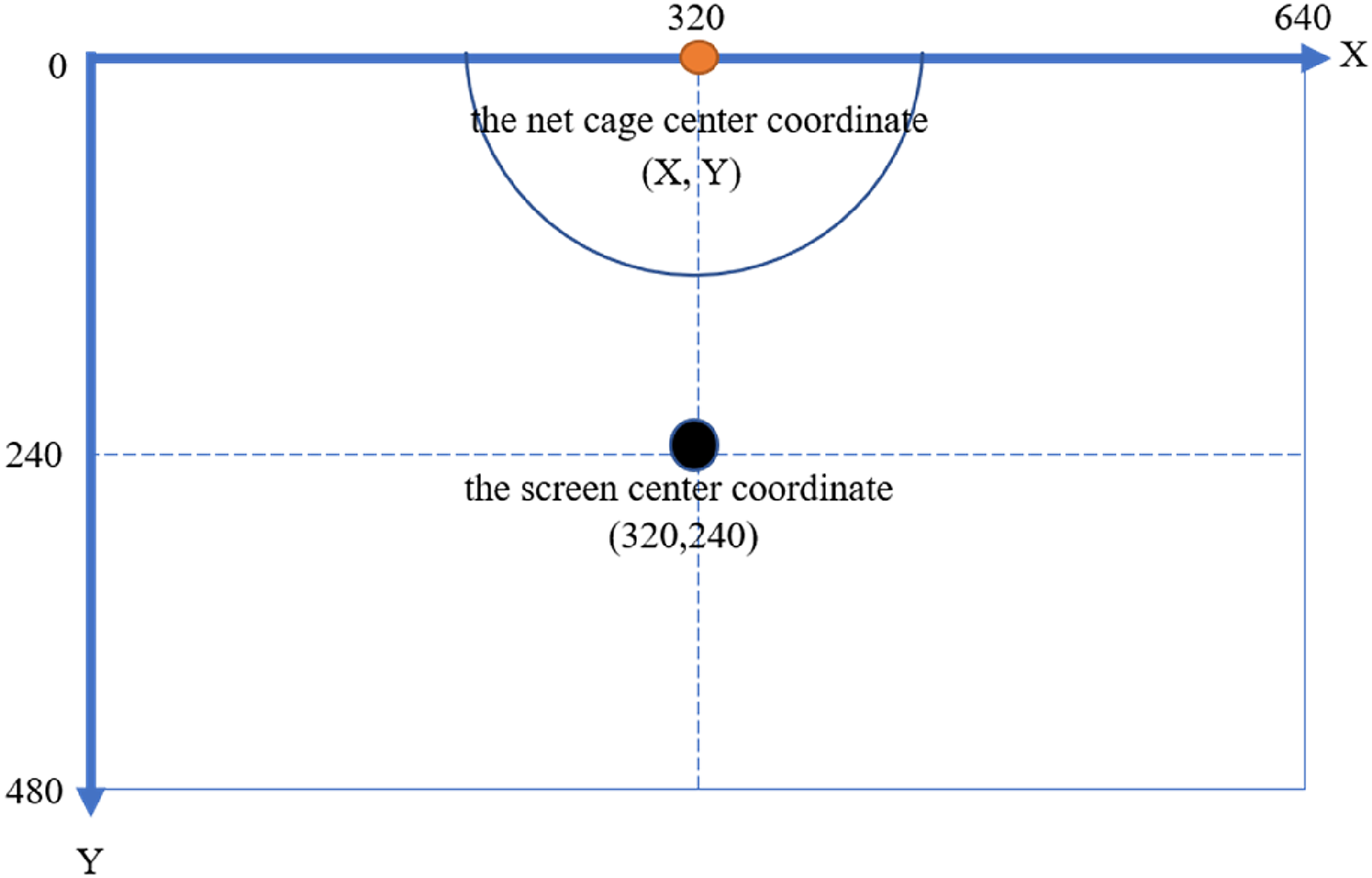
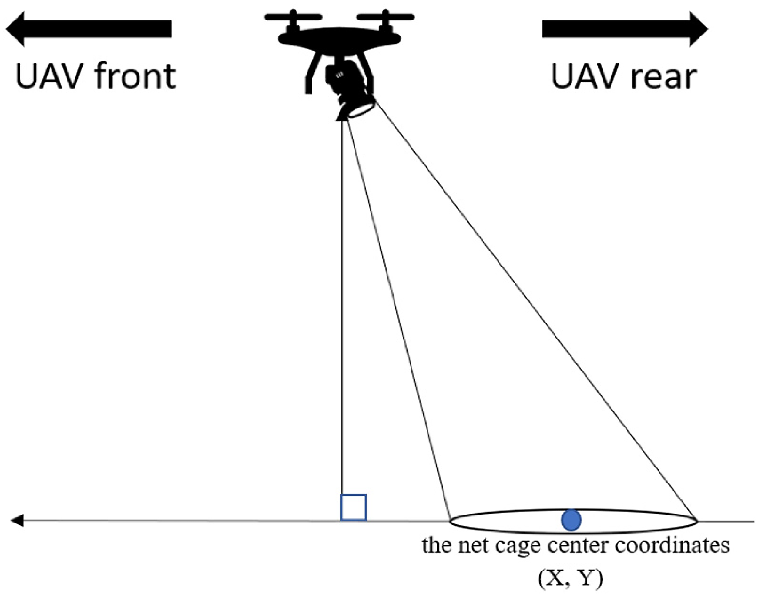
The coordinates of the target net cage were obtained by the GPS module and sent to the Pixhawk flight control board through the NVIDIA Jetson Xavier NX module. The UAV was then controlled by the Pixhawk and flew to the net cage location. GPS can be affected by weather factors and magnetic field interference. This leads to inaccurate positioning; therefore, in this study, image recognition was applied during the flight to assist in correcting the UAV positioning. When the UAV moved close to the target area, the image recognition process was turned on, and the net cage was identified based on the camera frame ratio. The length and width of the camera's picture output were, respectively, 640 × 480 pixels; therefore, the center point of the picture (X, Y) was (320, 240). When the UAV moved forward, the pitch angle of the gimbal gradually adjusted downwards until the net cage was within the boundaries of the camera frame.
The UAV controlled the gimbal angle adjustment when the target net cage was recognized. The procedure was as follows:
(1) When the target net cage is in the upper half of the camera screen, as shown in Figure 21:
(1-1) If the distance between the target center point and the screen center point is less than 35 pixels and the gimbal angle is greater than −90°, the UAV continues to move forward, and the gimbal continues to rotate downward.
(1-2) If the distance between the target center point and the screen center point is less than 35 pixels and the gimbal angle is approximately −90°, the UAV continues to move forward, and the gimbal remains motionless.
(1-3) If the distance between the target center point and the screen center point is less than 35 pixels and the gimbal angle is less than −90°, the UAV stays still, and the gimbal continues to rotate upward.
(2) When the net cage is in the lower half of the camera screen, as shown in Figure 22:
(2-1) If the distance between the target center point and the screen center point is greater than 35 pixels and the gimbal angle is greater than −90°, the UAV remains stationary, and the gimbal continues to rotate downward.
(2-2) If the distance between the target center point and the screen center point is more than 35 pixels and the gimbal angle is approximately −90°, the UAV continues to move backward, and the gimbal remains motionless.
(2-3) If the distance between the target center point and the screen center point is greater than 35 pixels and the gimbal angle is less than −90°, the UAV continues to move backward, and the gimbal continues to rotate upward.
(3) When the net cage is near the center of the screen but the gimbal is not rotating downward and approaching −90°.
(3-1) If the distance between the target center point and the screen center point is within 35 pixels and the gimbal angle is greater than −90°, the UAV continues to move forward, and the gimbal continues to rotate downward. The diagrams of the action are shown in Figures 23 and 24.
(3-2) If the distance between the target center point and the screen center point is within 35 pixels and the gimbal angle is less than −90°, the UAV continues to move backward, and the gimbal continues to rotate upward. The diagrams of the action are shown in Figures 25 and 26.
When the gimbal rotated downward (−90°) and the net cage position was in the center line of the camera screen, the left and right positions would be adjusted until the center coordinates (X, Y) of the net cage target object's bounding box approached the camera screen's center coordinates, thus confirming that the UAV positioning correction was completed and the UAV was located directly above the net cage.
Net cage is in the upper half of the screen diagram.

Net cage is in the lower half of the screen diagram.

UAV gimbal angle is greater than −90°.

The camera screen center point is directly below the target center point.
UAV gimbal angle less than −90° diagram.

The camera screen center point is directly above the target center point.
Experiment results
Target recognition comparison
In order to improve the image recognition accuracy, we collected net cage images from various angles, heights, and different light and shadow changes, to be used as the training and test data. After the four models were trained, the trained weights were used for image recognition to verify the differences.
(1) 100% Full Presentation in the Camera Screen
The vertical top view of the target is shown in Figure 27 and indicates the screen showed the complete net cage. The four types of YOLOv4-tiny got the same results, and the confidence score was 100%.

Comparison of 100% full presentation. (a) YOLOv4-tiny. (b) YOLOv4-tiny improved 1. (c) YOLOv4-tiny improved 2. (d) YOLOv4-tiny improved 3.
(2) 50% Presentation in the Camera Screen
As shown in Figure 28, when 50% of the net cage was presented on the camera screen, the confidence score remained above 90%, but the score for the original YOLOv4-tiny algorithm was only 88%.

Comparison of 50% presentation. (a) YOLOv4-tiny. (b) YOLOv4-tiny improved 1. (c) YOLOv4-tiny improved 2. (d) YOLOv4-tiny improved 3.
(3) Target Edge Presentation in the Camera Screen
When only the edge of the net cage was captured by the camera, only Improved 3 could recognize the target, and its confidence score remained as high as 86%. The other structures could not identify this image, as shown in Figure 29.

Comparison of target edge presentation. (a) YOLOv4-tiny. (b) YOLOv4-tiny improved 1.
(4) Target Recognition Failure
Even after using 1841 items of training data and 461 items of verification data, training 8000 times, and adjusting the output threshold of the confidence score to 85%, there was still a chance of identification failure. A comparison of the four models showed that only YOLOv4-tiny Improved 1 did not fail in recognition, as shown in Figure 30.

Comparison of recognition failure. (a) YOLOv4-tiny. (b) YOLOv4-tiny improved 1. (c) YOLOv4-tiny improved 2. (d) YOLOv4-tiny improved 3.
A comparison of the improvements is shown in Table 6, which shows that most of the modified YOLOv4-tiny algorithms were better than the original model. Regarding the FPS, Improved 2 was the fastest because its BFLOPS was the smallest and the YOLO output layer was only 13 × 13, but the mAP and accuracy were poor. Although the original YOLOv4-tiny still had the best mAP, the FPS, BFLOPS, and power consumption of the improved architectures were better than the original. Although we sacrificed some accuracy, the object could still be detected. In addition, the higher FPS reduced the error affecting the identification, greatly reduced the BFLOPS, and reduced the computational complexity, thereby reducing the power consumption of the onboard computer. This could greatly improve efficiency and save power consumption under long-term usage. Although the accuracy of the complete target image recognition was high, when only the edge was recognized, only Improved 3 could successfully recognize the target. The results indicated that the improved architectures were more optimal than the original architecture.
Comparison of improved result.
Field test
To enable the UAV to execute the proposed method smoothly and safely, we first simulated and verified our experimental results on the university campus. We set up a canvas with a net cage printed on it, as shown in Figure 31. The size of the net cage was about 15 m. In this experiment, the UAV only flew to a height of 8 m. We first sent the target GPS position to the UAV and executed the start action through a command given by the ground station, and the image recognition system was turned on after takeoff. When the UAV approached the net cage and the net cage was recognized, positioning correction was activated. After the correction was completed, the UAV altitude was lowered to an altitude of 5 m. The water quality sensor was then lowered for 10 s. After 10 s, the dual-motor winding system was used to retract the sensor, and the UAV returned to the take-off point to end the mission. The complete mission is shown in Figure 32.

UAV home position and canvas net cage position.
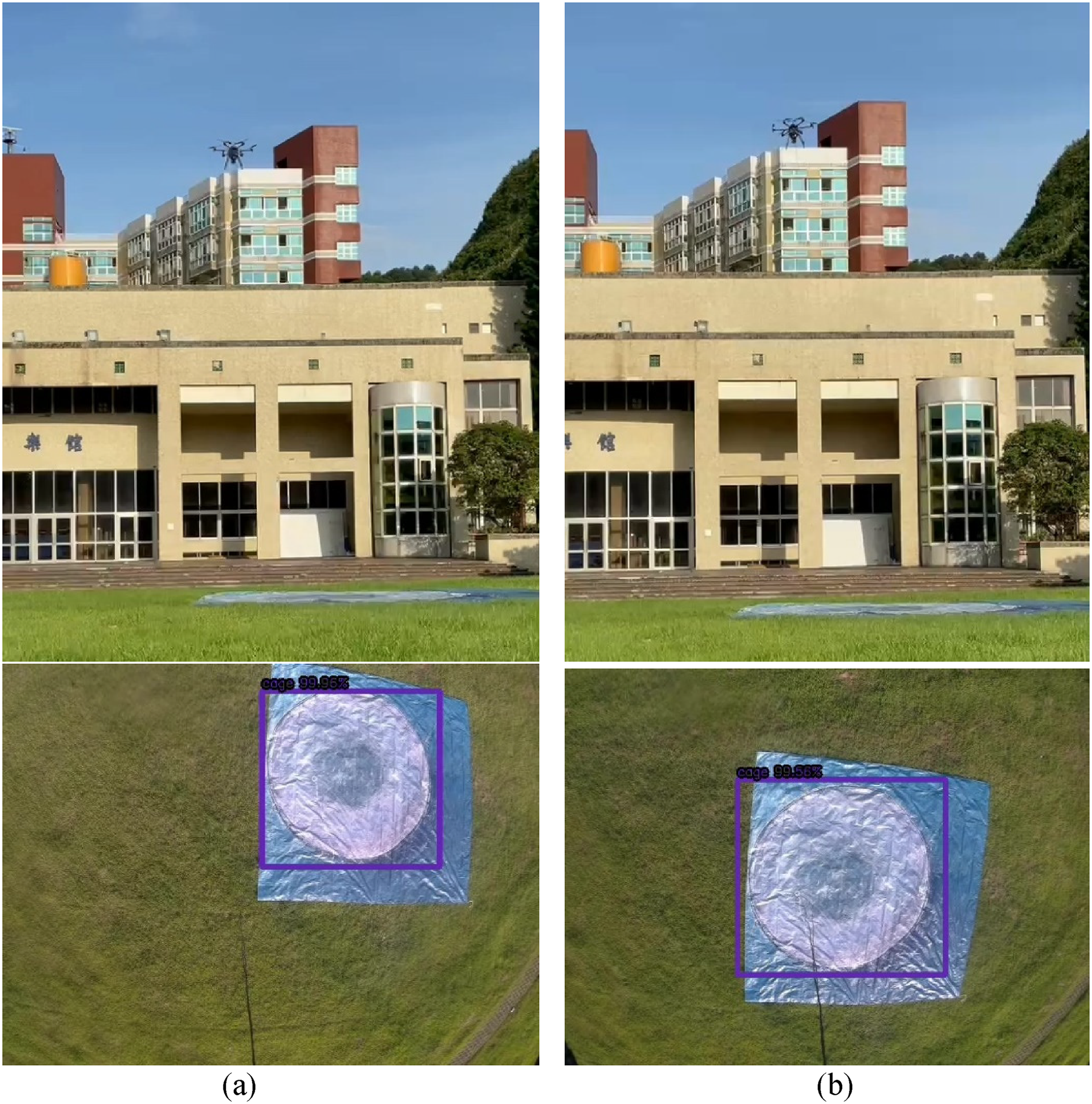
Complete performance of UAV actions. (a) Fix forward and backward, and shift right and left. (b) Fix above the net cage. (c) Move down to 5m height. (d) Drop the sensor. (e) Pull up the sensor. (f) Return to home position.
In the field test, a square net cage was used. This net cage was different from the original net cage used for training, as it was a square net cage (as shown in Figure 33). The training weights were changed, and then a flight test was performed. This time, the actual application used the original YOLOv4-tiny and Improved 1 models. However, identification errors still occurred. The UAV could not be adjusted to the correct position when the original YOLOv4-tiny was used, but the Improved 1 model could stabilize the identification box. The original YOLOv4-tiny and Improved 1 image recognition and correction screens are shown in Figure 34, and the sensor-dropping procedure is shown in Figure 35.

Net cage of field test.

Image recognition and correction screens on UAV. (a) Original YOLOv4-tiny could not identify the net cage position. (b) YOLOv4-tiny Improved 1 recognized net cage and its position.

Dropping the sensor into the net cage.
Conclusion
This study mainly discussed how to use image recognition to help a UAV find the target and perform positioning correction through a recognition screen. At the same time, considering the applications of UAVs, it was necessary to improve power consumption. YOLOv4-tiny can detect the target at a faster speed than the ordinary YOLOv4 algorithm. This study used an improved CNN structure to result in an even faster speed than YOLOv4-tiny and reduce the number of calculations. At the same time, the power consumption was also reduced, making it more suitable for UAV applications. The improved neural network structure could reach up to 77 FPS while reducing the image delay. Different types of YOLOv5 are being studied, and the results will be submitted at the end of this year. Preliminary results show that the computation time of YOLOv5s reduces by 15% but the object confidence score of YOLOv5s drops by 10%. In this study, the accuracy of cage location is very important for dropping the sensor in the target cage. Since the improved YOLOv4-tiny has at least 66 FPS, this is good enough for real-time cage recognition. The UAV positioning correction speed was faster, and the proposed method was more accurate than using GPS alone. Even if the GPS encountered interference or failure, the proposed method could support UAV positioning correction through imaging assistance. The proposed system could be applied to aquaculture methods to reduce labor cost and water quality detection time. In cage aquaculture, most water quality sensors can measure dissolved oxygen, pH, temperature, salinity, nitrogen, and phosphorus. In our study, the RBRcoda3 sensor was used. The weight of this sensor is 180 g and its size is 28 mm × 116 mm. This series of sensors can track water parameters, such as temperature, depth, salinity, dissolved gases, pH, and many others. Since this study puts a focus on image processing and UAV control, water measurement and analysis are not included in this paper.
Footnotes
Declaration of conflicting interests
The authors declared no potential conflicts of interest with respect to the research, authorship, and/or publication of this article.
Funding
The authors disclosed receipt of the following financial support for the research, authorship, and/or publication of this article: This work was supported by the Ministry of Science and Technology, Taiwan (grant number MOST 110-2634-F-019-001).
Author biographies
Wei-Yi Liang earned his MSc degree in Communications, Navigation and Control Engineering from the National Taiwan Ocean University, Keelung, Taiwan. His research focuses on unmanned aerial vehicle control, deep learning, object identification, neural network applications, and image recognition.
Jih-Gau Juang is currently a distinguished professor with the Department of Communications, Navigation and Control Engineering, National Taiwan Ocean University. He obtained his PhD degree in Electrical Engineering from the University of Missouri, Columbia, USA. His research focuses on artificial intelligence, intelligent control, intelligent systems, vehicle control, and robotics.