
Abstract
Background
Many faults occur in the modular multi-level converters (MMCs), including unbalancing capacitor voltage, lower and upper arm unbalancing, the line to line voltage unbalancing, sensors and actuators fault, system fault, and sub-modules fault in high as well as medium voltage applications.
Introduction
Several fault-tolerant approaches are presented to overcome these problems, such as active fault-tolerant control system (AFTCS), passive fault-tolerant control system (PFTCS), hybrid fault-tolerant control system (HFTCS), redundant system technique, special power circuit with the controller, and zero sequence voltage methods, which we will explain extensively in this article.
Methodology
This review emphasizes the types of faults in the MMCs and discusses the protection methods under failure conditions. The MMC is more popular in high voltage applications because it not only improves the quality of the grid but also has good harmonic performance in high power transmission. There is no need for any isolated dc sources to operate it. When faults are removed, the efficiency and reliability of the system will be increased.
Results
This extensive explanation of the current literature on MMC fault diagnosis and control techniques will conclude which methods provide a more valuable solution. Finally, this paper discusses the best approach to reduce MMC faults and provides a future research direction to the readers.
Keywords
Introduction
The modular multi-level converter (MMC) is commonly used in a diverse number of applications, i.e., high power transmission in grid stations,1–3 motor drives, 4 and energy storage devices. 5 MMC replaced many voltage source converters and multi-level inverters. It has shown much attention in the industry, and it has given a suitable solution in high power transmission applications. 6 The MMC consists of a series of sub-modules (SMs), including many switch modules, called the half-bridge and full-bridge modules. Due to the usage of many switches, switch faults have occurred in MMC, which is one of the main reasons for the system's failure. The switching faults include open switch fault caused by over-temperature and short switch fault caused by overcurrent and high temperature as shown in Figure 1. Besides many types of faults, the most common is unbalancing issues such as lower and upper arm unbalancing, capacitor voltage unbalancing, and line to line voltage unbalancing in SMs.7–8 The other faults are gate misfiring faults and systems faults. The system faults include AC side and DC side which are basically critical faults that cause the whole MMC system failure. In some topologies of MMC DC link capacitors are also the main reason of MMC failure. 9 So, it is essential to provide compensation to MMC in a faulty condition. Fault diagnosis is the crucial factor in MMC because if any fault occurs in MMC, it will lead the complete system to fail. To overcome these problems, the fault-tolerant control approaches are extensively discussed in this article.

Structure of MMC under faulty conditions. 10
There are lots of fault detection approaches for MMC as described in11–14 which include park transformation, Fourier transform (FT), wavelet transform (WT), the comparison between measured and reference values, fuzzy logic, and a lot of neural network (NN) approaches. Two other approaches commonly used to detect fault are signal processing (SP) based and artificial intelligence (AI) based. In SP, feature extraction and classification algorithms were used, and in AI, trained algorithms were used to detect faults in MMC. 15
After fault diagnosis, it is a challenge to overcome these faults. To remove these faults, several fault-tolerant control approaches were used. Fault tolerance control is one of the best approaches used to prevent the system from shutdowns and increase the system's reliability. It is also used to fend off the system under failure conditions. In fault-tolerant control approaches, redundancy is one of the most important strategies to protect the MMC from faults. To overcome switch fault in MMC, redundancy is used to make a copy of the switch attached parallel to the faulty switch, as proposed in. 16 Duplex and Triplex redundancies approaches have been used where two or three copies of switches are required, attached parallel to faulty switches in MMC. Another method added zero-sequence voltage injection in17–18 to the reference voltages to control the arm voltage and current unbalancing issues produced in MMC. A special power circuit with a controller deals with MMC faults. 18 Another approach was used in 19 to reduce power oscillations generated from signal phase fault of lower and upper arms of capacitors.
This paper evaluates the detailed review of different fault diagnoses and fault tolerant control techniques for MMC based on the above data. Section II presents the methodology of varying fault diagnosis and control techniques for MMC. Section III consists of a comparative analysis of the best approach to detecting and compensating for MMC faults. Finally, section IV consists of the conclusion and future work of the paper.
Fault diagnosis and control techniques for MMC
This section summarizes the current literature results related to fault diagnosis and fault-tolerant control approaches for MMC.
Faults diagnosis techniques
In fault diagnosis, first, we monitor whether the MMC was operating in normal or faulty conditions. If MMC does not operate normally, the system detects the fault using the appropriate method. There are lots of fault detection approaches that are extensively discussed below:
Submodules faults
There are two types of faults that occur in SMs of MMC, open circuit and short circuit switch faults. If short circuit fault occurs in the SMs of MMC the voltage will be reduced in the faulty interval. We have simulated 3-phase MMC with four half-bridge SMs in both the lower and upper arm of MMC in each phase to observe all modes of faults as shown in the structure of MMC in Figure 1. The pulse width modulation (PWM) generator is used to control the Switching of MMC. First, we observe the lower and upper arm voltages under normal conditions, when no-fault occurs in the SM of MMC. Figure 2 shows the MMC lower and upper arm voltage under no-fault.

MMC lower and upper arm voltage under no fault.
Then, we inserted a short circuit symmetrical fault in the range (0.02–0.03s) to observe the MMC under faulty conditions. The lower and upper arm voltage of MMC is reduced due to a short circuit fault as shown in Figure 3. If an open circuit fault occurs in SMs of MMC, the voltage across the faulty switch of SM is maximum in the interval of fault.

MMC lower and upper arm voltage under short circuit fault.
This mechanism is used to diagnose the open switch fault in MMC. We have to observe the voltage in both AC and DC sides of SMs in MMC in this approach. The half-bridge SM in normal and faulty conditions has been shown in Figure 4.

Half bridge sub modules SMs: (a) normal condition (no fault) (b) faulty condition (open circuit switch fault). 20
In normal conditions, if the upper switch is turned on and the lower switch is turned off, both AC and DC sides voltage and current should be the same. In reverse condition, if upper switch T1 is off and lower switch T2 is on, the voltage and current should be zero on both AC and DC sides. If any fault has occurred, the voltage and current value will differ from normal conditions. Considering this scenario, the author proposed a method in 20 of fault diagnosis based on sliding mode observer (SMO). By using the above approach, we can easily detect open switch faults in the sub-module of MMC. This approach is easily implemented in microcontrollers, independent of frequency operation, and implemented in half-bridge and full-bridge SMs. The one limitation of this approach is that inaccuracy was monitored in measured parameters, and imbalances occurred in voltage profiles.
In the proposed technique, 21 a fault diagnosis method and removal of this fault based on state SMO was proposed for insulated gate bipolar transistors (IGBTs) open circuit failures in SMs of MMC. This method quickly detected open circuit faults, which is the main reason for the failure of SMs of MMC. The first fault is detected using the observer method and then removed by bypassing faulty SMs with healthy ones. There is no use of any additional hardware components, and no interruption happens during the whole process. Still, one deficiency of this method concerning fault detection is that it could not identify how many IGBTs failed when multiple IGBTs are faulty. The authors used simple SMO in 22 and integral SMO in 23 to detect and isolate the multiple open switch fault in MMC. The essential criteria of this method are to find the difference between the measured value and the observed value of the voltage of the capacitor in SMs. If the difference is higher than the threshold voltage, the SM is faulty. The implementation of this method is straightforward, with no additional sensor requirements. The main advantage of this method is to diagnose and isolate multiple open switch faults within 20ms. In24–26 authors also used SMO, modified SMO technique, and discrete-time SMO, respectively. All methods aimed to detect faults in SMs that reduced voltage sensors and simplified communication systems. In 27 a triple star bridge cell (TSBC) of MMC with the three SMs in one cluster was implemented in piecewise linear electrical circuit simulation (PLECs) software to detect open switch fault in SMs. This method is efficient, and easy to understand, and no additional measuring devices were used.
In 28 the authors proposed an SMO technique based on Lyapunov theory to detect open circuit fault in SMs. This method detects open circuit fault and tells the type of fault in MMC. For open-circuit fault diagnosis, first fault features were extracted, and the fault location in MMC was calculated using SMO. The results verified the usefulness and accuracy of this technique.
In29–33 the authors implemented an extended state observer (ESO) technique to detect and localize open circuit faults in SMs of MMC. By taking the difference between observed and theoretical values, we can easily detect fault using ESO. To find the change rate of fault tracking differentiator (TD) method was used. The accuracy of this method is better as compared to simple SMO.
In 34 the authors implemented an open circuit fault detection method based on weighted amplitude permutation entropy (WAPE) and the evidence fusion theory (EFT). The experimental results show the feature extraction ability of the WAPE method is better than SMO. The main advantage of this method is easily detected multiple faults in SMs.
In 35 the authors proposed a trigging event mechanism (ETM) to diagnose and locate open circuit faults in SMs of MMC. In ETM, the fault diagnosis is activated in this condition, where capacitor voltage and current are combined. The proposed approach reduces the controller's computation time and does not use extra hardware.
In 36 the authors implemented an arm current reshaping-based method to diagnose open circuit faults in SMs under overvoltage conditions. The arm current is reshaped to reduce discharging of the capacitor under faulty conditions. The proposed method is reliable and concentrates 50% of extra hardware.
The Authors in 37 proposed a machine learning (ML) classifier-based technique with feature extraction and random forecast to diagnose and locate open circuit faults in SMs. In the proposed ML technique, the author first trains the data set, then test the data set based on fault diagnosis and localize (FDL) classification. The accuracy of the proposed method is very high and easily verified by the confusion matrix. In 38 authors presented a convolutional neural network (CNN) and auto deep learning neural network (DNN) to diagnose open switch faults in SMs of MMC. The fault diagnosis accuracy of the DNN technique is better than CNN because of training time.
For short circuit non-permanent faults in DC lines for MMC in high voltage direct current (HVDC), a new method was proposed in 39 based on redundancy. According to this method, every SM was bypassed by using a dual switch consisting of double thyristors to eliminate the freewheeling effect of the diode. The advantage of this method is that it clears faults very fast. The system automatically recovers itself for nonpermanent faults on dc lines; however, the drawback of this method is having an issue when we use it on multiple ends in HVDC. So, it could not be extended to multi-terminal voltage source converter (VSC) for HVDC systems.
In 40 a fault detection technique based on wavelet transform (WT) and adaptive neuro-fuzzy inference system (ANFIS) to diagnose short circuit faults that occurred in SMs of MMC was proposed. According to this technique, features are extracted using wavelet transform in faulty conditions, then fuzzy logic algorithm which was already trained is used to diagnose the short circuit fault. In this method, no additional sensors are used as well as high accuracy was achieved compared to the neural network method. The authors in 41 used wavelets transform with a support vector machine (SVM), a more transparent classification technique. It used a 17 level MMC with high performance to detect short circuit fault in MMC. This technique accurately identifies the faults in SMs and reduces additional sensors. Another method in 42 was used to detect open and short circuit faults based on SVM, commonly used in electronic devices to detect faults. Furthermore, the total harmonic distortion (THD) effects on the system were also mentioned in. 43
In 44 the authors proposed a new fault detection algorithm to detect open and short circuit faults using power electronics switches. This method is easily implemented and does not require measuring sparse voltage. The advantage of this technique is to detect multiple faults at a time in both open and short circuit fault conditions.
In 45 the authors implemented an adaptive fault current limiting control (AFCLC) method to detect the short circuit faults in MMC. This method is highly efficient, fast, and does not need to use various current limiting devices by comparing existing methods. The simulation results prove the accuracy of this method.
System faults
There are primarily three system faults in MMC: AC side, DC side, and whole system fault. In 46 the authors proposed a method to diagnose DC side fault. In this approach, high-frequency components were extracted through wavelet transform to detect fault by taking the difference of transient voltages. We can easily protect the system from DC faults without checking system and power flow communication using this method.
For AC side faults, in, 47 the authors proposed a method to detect and classify faults on the AC side of MMC. The feature extraction phenomenon uses discrete wavelets transform (DWT) and modulus maxima (MM). The author implemented a fault diagnosis algorithm using Matrix Laboratory (MATLAB) software. This method's main advantage is detecting and classifying faults very fast. The fault detection time was just 0.2 ms, and the AC line fault time classification was 1 ms. In 48 the authors proposed a method to diagnose AC system unbalancing fault. AC system unbalance fault can be detected by analyzing the second-order harmonic. In this technique, a dc voltage ripple suppressing controller (DCVRSC) was used to remove these harmonics in DC voltage for MMC. This system cannot detect faults in those conditions where higher-order harmonics have occurred.
In 49 the authors implement an open circuit fault detection method to prevent the whole system from shutdowns based on the Kalman filter and optimized SVM. The fault is detected using KF and located fault by using optimized SVM. The technique was implemented in 11-level MMC using MATLAB Simulink. The accuracy of this method was very high.
Unbalancing faults
Many unbalancing issues occur in MMC, including unbalancing capacitor voltage, the line to line voltage unbalancing, and lower and upper arm unbalancing in sub modules. In50–51 the authors proposed a fault diagnosis technique based on passing current and fault localization method was implemented to balance capacitor voltage. When a fault is detected, a control approach based on redundancy is also implemented to remove faults from MMC. This method has rapid detection capabilities and medium control approach to remove faults from MMC. In 52 the authors found SMs capacitor voltage maximum and minimum values to detect the unbalancing issue in MMC based on the arm average model. According to this model, if the maximum and minimum values are according to normal operation, there will be no balancing fault in capacitor voltage. If there is a vast difference between lower and upper values, the unbalancing fault is detected in MMC.
In 53 the authors proposed a zero-sequence voltage injection (ZSVI) method to detect unbalancing of arm current, which causes the phase unit loss in MMC. A close-loop ZSVI method is implemented to overcome phase unit loss, which is more accurate and reliable verified by transient electromagnetic simulations.
In54–56 the authors implemented an ANN-based technique to remove the unbalancing in capacitor voltage. The proposed approach reduces ripple from capacitor voltage and quickly finds circulating current without analytical computations. The ANN first trained the data using the MMC simulation model and then verified the proposed method results.
In57–59 the author proposed a full-bridge sub-module (FBSM) based technique to remove unbalancing between arms of SMs. Due to unbalancing of arms, the overvoltage issue is produced in MMC. To reduce this voltage, the arm current communication process should be limited. If the voltage is decreasing, the energy between arms is balanced automatically.
Faults tolerant control techniques
The fault was detected in MMC by using various techniques already discussed above. Now to overcome these faults, detailed literature on Fault-Tolerant Control (FTC) techniques is given below:
AFTCS
The AFTCS consists of a fault detection and isolation (FDI) unit and reconfiguration mechanism. If any fault occurs in the MMC sensor side or actuator side, the FDI unit detects the fault, and then isolates and reconfigures it by replacing the faulty value with a healthy value. The observer-based mechanism is used parallel with a plant which generates an estimated value of sensors and feeds the value to the controller (Figure 5). By taking the difference between the actual value and estimated value, if the deviation is very large that means the fault occurred in MMC, if the error between the actual value and the estimated value is within limits then the controller declares no fault in MMC. If the fault is detected in MMC, the next step is to isolate the fault by replacing the correct value which tells the observer-based mechanism running parallel with the plant to maintain the stability of the system and avoid whole system shutdowns. To warn the operator about fault, an alarm is annunciated to carry out necessary actions.60–65
There are lots of techniques used to implement AFTCS.
For fault estimation one of the best techniques which are mostly used is called the Kalman filter (KF). The faults estimation in KF in two steps time update and measurement update by comparing residuals which are extensively discussed in these articles.66–68
In 69 the authors discussed AFTCS approaches in MMC under SMs failure conditions. To use multiple redundant SMs, the size and weight of the system are increased. To overcome this problem, a non-redundant approach was implemented in this article.
The linear parameter varying method (LPVM) is also used for fault estimation. In 70 a discrete LPV method is used for actuator’s fault estimation. A robust fault estimation method is proposed as well which was the main contribution of this paper by using LPV with linear matrix inequality (LMI).
The neural network with the back stepping approach is presented in articles.71–73 The first observer is implemented which gives estimated values of faulty modules. Then a back stepping method is used to remove these faults.
The advantage of AFTCS in MMC, we can easily remove multiple faults such as sensors and actuators faults but due to multiple fault detection, the speed is slow due to high computations. The decision of fault detection can also be wrong if a large noise is added to the system, therefore an intelligent control is required to detect fault which is discussed below.74–75
PFTCS
The architecture of PFTCS is quite simple compared to AFTCS, it is basically a robust control. In PFTCS, the fault diagnosis and isolation and controller reconfiguration are not implemented and the system works only with the same parameters under faulty and normal conditions (Figure 6). Due to the elimination of the controller and detection module, the computations of the system are very small, and very fast. If any fault occurs in sensors, actuators and system, the PFTCS is enabled and rapidly detect fault. The main advantage of PFTCS is that it can easily tolerate fault in noisy and non-linearity conditions due to robust architecture. 64 , 76
If the fault is critical and quick in MMC, the AFTCS will fail in these conditions because of the time to detect the fault. In these situations, a PFTCS is used which is quite simple and fast.76–78
The PFTCS was implemented in79–81 and robust control in 82 to overcome the single point failure. Single point failure is basically a critical fault; if this type of fault occurs the whole system will be shut down. Therefore, fast and accurate detection is required to overcome this issue. The main advantages of these articles are to detect fault very fast and easily diagnose the fault in uncertain conditions.
HFTCS
The HFTCS is basically the combination of both active and passive FTCS.
There are some advantages and disadvantages of both AFTCS and PFTCS; a hybrid combination as shown in Figure 7 of both gives many benefits. By using HFTCS, we can easily detect multiple faults as well as quick fault detection. The time delay issue of AFTCS and multiple fault detection issues of PFTCS are easily solved by using HFTCS.83–85

The architecture of AFTCS. 64
In 86 the authors proposed hybrid FTCS for air–fuel ratio control of internal combustion gasoline engines (ICGE) based on KF and triplex hardware redundancy. The proposed method consists of both types of active and passive FTCS is used for multiple fault detection in ICGE very fast and also overcomes faults using triplex redundancy. The advantage of this method easily detects multiple faults and gives a quick response of fault detection but in the case of harmonic distortion in ICGE the fault estimation is affected. In another paper, 87 the author implemented hybrid FTCS against actuator faults and model uncertainties to overcome the above paper’s drawback. In the case of harmonic distortion, the proposed method easily detects and overcome faults under actuator’s faults.

The architecture of PFTCS. 64

The architecture of HFTCS. 64
Redundancy
Redundancy is one of the essential strategies commonly used to protect the MMC from faults. In88–89 redundant strategies were implemented based on duplex and triplex redundant models to remove faults. As shown in Figure 8, Duplex and triplex redundancies mean attached two or three copies of modules parallel to faulty MMC modules, enhancing the system's durability and reliability.
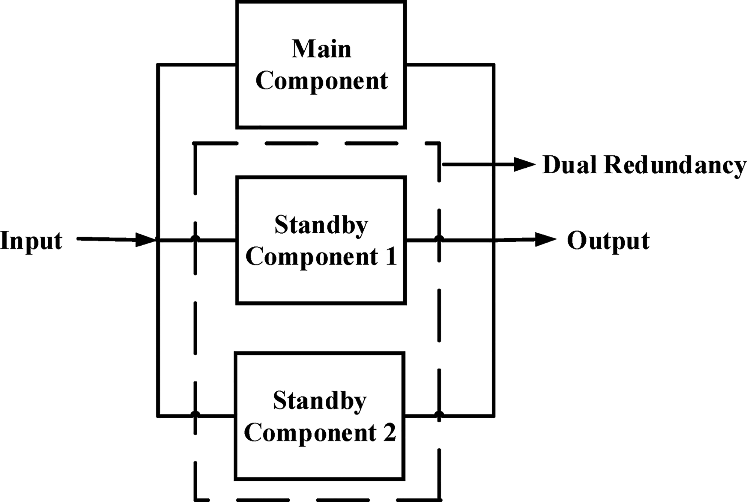
Triplex redundant system.
In90–91 SMs of MMC fault controlling capabilities were achieved by using redundant sub-modules and integrating extra converters to bypass these faulty sub-modules. This redundant approach is shown in Figure 9 using the neural network technique of machine learning. The histogram analysis is used to extract features, and these features are used as the input of neural networks (NNs). The multi-layer NNs have been used to detect the faults. If all faulty sub-modules are smaller than redundancy in sub-modules, it will easily overcome the faulty condition by bypassing the faulty sub-modules. If all the faulty sub-modules increase in number compared to redundancy in sub-modules, then extra modules are required to connect to the arm of MMC.

Redundant system of MMC with extra SMs.
In21,92–93 the authors proposed fault detection and control methods based on state observers to remove open switch fault in SMs of MMC. This method quickly detected open circuit faults, which is the main reason for the failure of SMs of MMC. The first fault is detected using the observer method and then removed by bypassing faulty SMs with healthy ones. There is no use of any additional hardware components, and no interruption happens during the whole process. Moreover, in,94–95 the authors proposed insulated gate bipolar transistor (IGBT) short circuit and open circuit faults to protect from overcurrent, which damages the switches of the arm of MMC. Due to a short circuit, an overcurrent flows in the system. For this purpose, the diode protection was also used parallel with switches.94–95
In 96 the authors implement a fault-tolerant technique for MMC based on the control automation technology Ether CAT communication protocol. If the SMs are very large, the complexity of hardware structures and chances of fault occurrence is increased. For this purpose, a high-speed digital communication network is required for both the central calculation unit and SMs. One limitation of this method is that the controller becomes heavier due to many SMs being used. A fault-tolerant method has been proposed in 97 for MMC based on modulation. The author used a carrier rotation algorithm to balance the voltage of SMs based on pulse width modulation (PWM). This method balanced power as well as voltage in SMs. It will enhance the system's durability, and manufacturing of hardware costs also be reduced.
Control strategies for balancing capacitor voltage
The voltage unbalancing is a critical issue in SMs of MMC. To overcome this issue, authors in98–99 had proposed a method to balance capacitor voltage in MMC. This method uses pulse width modulation (PWM) based on the phase shift carrier technique to balance capacitor voltage. In this method, there is no need to measure the current in the arm of MMC when we are balancing capacitor voltage, and manufacturing cost is also reduced.
If we increase the levels of multilevel converter, the output of MMC will be smoother but the issue of unbalancing of capacitor voltage is occurs. To overcome this fault, in 100 the authors implemented a control strategy based on Proposal Integral (PI) controller. The proposed method not only balance capacitor voltage but also minimizes the circulating current. The main advantage of this technique is having high efficiency, reliability and improved power quality.
The authors implemented a predictive control strategy in 101 to balance the capacitor voltage without any changes in AC. The author used a model-predicted control strategy, which has the advantages of cost function minimization and eliminates circulating current to balance capacitor voltage.
Another technique was proposed in, 102 a simplified nearest level control (NLC) method for balancing capacitor voltage. This method does not require redundancy during time triggering, and capacitor voltages are also balanced in open and closed-loop applications.
In 103 the authors proposed a fault-tolerant control technique for SMs of MMC. This method balanced the three-phase current and voltage when any fault occurred in switching devices. In this method, zero-sequence offset of the three-phase signal was used. Due to this, the line-to-line voltage and current are balanced. Additionally, it does not need any redundant SMs, which would reduce the cost.
Spacial power circuit
Where redundancy is one of the most common strategies used to protect MMC from faults, special power circuits with controllers were also famous for removing faults.
In 104 the authors implemented a control method based on discrete half-bridge SMs to compare the results of continuous model approaches. This technique's main advantages are removing power oscillations due to faults, self-stabilizing the voltage, and balancing the capacitor’s lower and upper arm voltages. In105–106 the authors used the circulating current suppressing controller (CCSC) technique to balance the inner current in MMC. The advantage of this technique is that the internal current's efficiency increases without increasing the arm reactance. In 107 the authors described three state-space models and controllers designed based on CCSC. In this technique, two, six, and ten models were used depending upon efficiency requirements. The ten models are more efficient than the two and six models because the lower models ignore the second harmonics and CCSC. The author implemented these models in MATLAB Simulink and verified the accuracy of models in both the time domain and frequency domain.
In 108 a model-based fast model predictive control (MPC) approach is used to balance capacitor voltages in MMC. It has balanced the capacitor voltage, but high computational time is required to implement MPC. The author proposed a fast MPC method with a reasonable cycle time for finding reference voltages. This method is also used in other multi-level converters. A predictable control strategy is implemented in 109 to regulate 3 phase current of MMC. The author in 109 verified the problem of simultaneously passing current and capacitor voltage unbalancing in MMC. To overcome these problems, the authors proposed a direct model predictive power control (DMPPC) approach to control power simultaneously, passing the current and balancing the capacitor voltages very fast. 109 So, this DMPPC 109 provides better steady-state performance and low computational time required than the MPC approach. 108
Comparative analysis
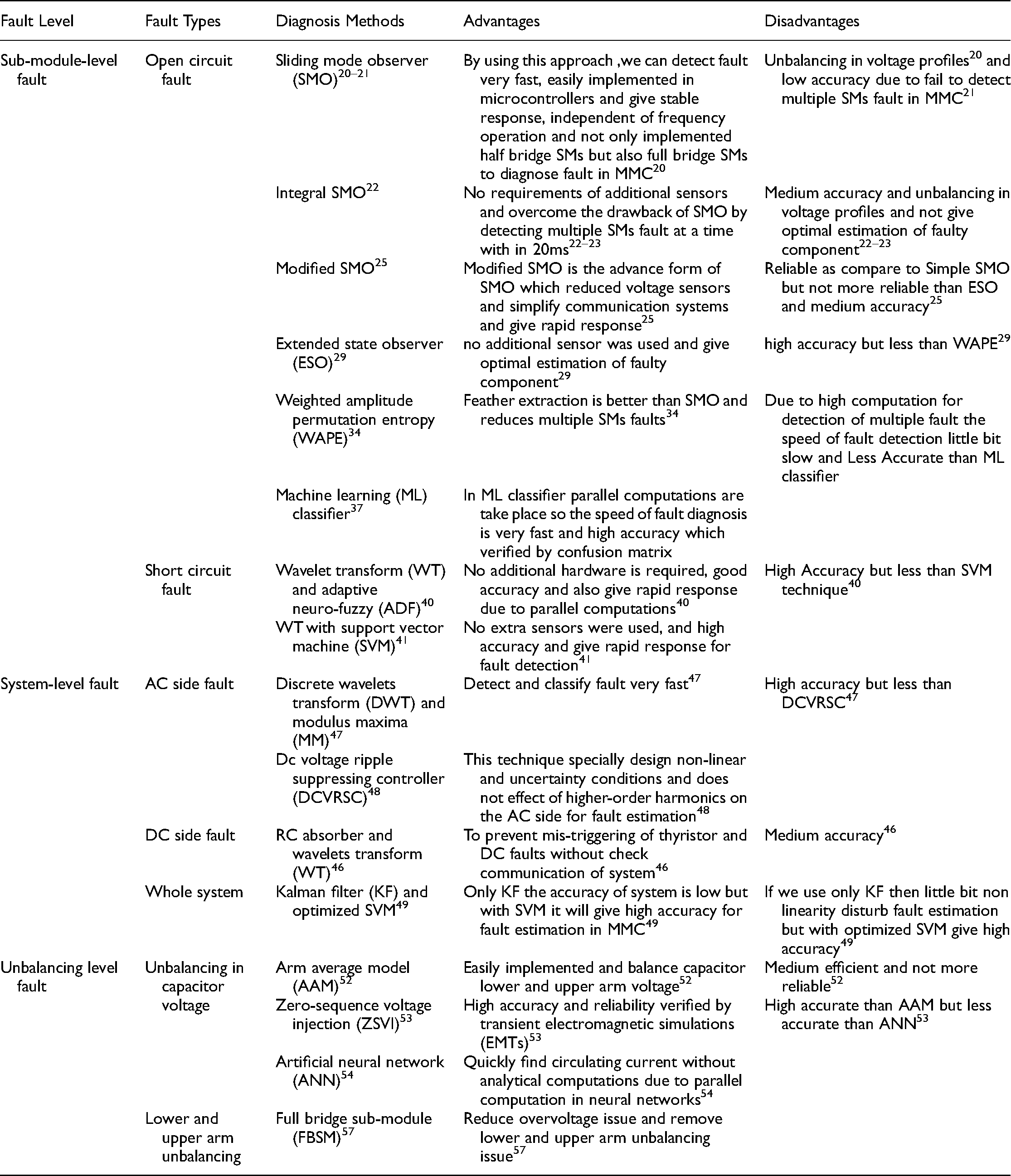
Tables 1 and 2 show the complete comparative analysis of different fault diagnoses and fault-tolerant control techniques used in MMC. These tables also verified the advantages and limitations of each method, thus providing a future path direction to the reader.
Comparative analysis of different fault diagnosis techniques in MMC.
Comparative analysis of different fault-tolerant control techniques in MMC.

Future research directions
Based on detailed literature, many fault diagnoses and fault-tolerant control approaches have been presented in this paper. For fault diagnosis in SMs, the ML classifier approach is best to detect open circuit fault in SMs of MMC in uncertainty conditions. This technique gives high accuracy as compared to other existing methods that the confusion matrix can verify. For system fault, discrete wavelets transform (DWT), and modulus maxima (MM) are the best technique to detect and classify AC system fault in MMC in non-linear conditions because of their fast detection and classification. The fault detection time is just 0.2
Conclusion
In this paper, we have discussed several methods of fault diagnosis and FTC techniques in MMC under failure conditions. Several faults occurred in MMC, such as SMs fault, system fault, and unbalancing fault. For SMs faults, open circuit and short circuit faults have commonly occurred. The system faults include the AC side, DC side, and whole system faults. The other faults are unbalancing in capacitor voltage, lower and upper arm unbalancing, and line to line voltage unbalancing in sub-modules when using MMC in HVDC systems. This paper provides a detailed comparative analysis of different latest fault diagnosis techniques in MMC with the pros and cons of each method to pave a future research direction for the technical experts.
Similarly, several fault-tolerant control approaches are also presented to control these faults, such as the redundant system technique, zero-sequence voltage injection method, and special circuits with controllers, extensively discussed in this article. From this extensive explanation, we provide a solid background related to the advantages and limitations of each fault-tolerant control technique in MMC, thus providing a future research direction for the technical experts.
Moreover, the main applications of MMC are that it is more prevalent in high voltage applications because it replaced many voltage source converters and multi-level inverters and also improves the quality of the grid in high power transmission. Considering future prospects, no doubt the maintenance cost of MMC in high voltage transmission is very high. However, with the continuous effort of technical experts in this area, hopefully, this problem will be resolved, and in the future, the cost of MMC should be further reduced.
Footnotes
Declaration of conflicting interests
The author(s) declared no potential conflicts of interest with respect to the research, authorship, and/or publication of this article.
Funding
The author(s) received no financial support for the research, authorship, and/or publication of this article.