
Abstract
With the increase in power and flow of emulsion pumps, pump valves are more likely to be damaged during long working hours, Therefore, it is important to ensure the reliability of pump valves at all stages. However, there are still some problems that need to be solved urgently. For example, whether the actual dynamic characteristics of the valve are consistent with the simulation results, and whether the simulation can replace experiments to provide a reference for the design improvement of the valve. At the same time, what is the failure mechanism of the valve, and what methods can be used to find the early failure of the valve. Therefore, the dynamic impact contact characteristics and fault diagnosis of valves of reciprocating piston pumps were investigated both experimentally and numerically. They were analyzed using AMESim simulation and U-Adolph theory, respectively, to predict the dynamic characteristics of the valve. The effect of spring stiffness on the dynamic characteristics of the valve was also investigated. The numerical analysis and analytical results are in good agreement with the experimental results, which provide an important reference for the development of new horizontal five-cylinder single-acting reciprocating pumps. In addition, finite element analysis was used to study the impact contact characteristics of the discharge valve closing under different valve diameters. The failure mechanism of the pump and valve was revealed, a fault diagnosis method was proposed, and the effectiveness of the method is verified by experiment.
Keywords
Introduction
Reciprocating piston pumps are classified as positive displacement pumps, which are widely used in the mining, gas, chemical, petroleum, and other industrial applications.1–3 The self-acting valves located at the suction and discharge ports of the liquid end of reciprocating pump are employed to control the intake and discharge of the fluid. The dynamic characteristics of the reciprocating piston pump valve are related to the design of valve parameters, and the study of impact contact characteristics is related to the failure mechanism of the valve. Therefore, the dynamic and impact contact characteristics of reciprocating piston pump valves not only have an important effect on the performance and durability of the pumps, but also affect the noisiness of the pump operation.4,5
Analytical, numerical and experimental studies have been carried out by many researchers, in order to explore dynamic and impact contact characteristics of reciprocating piston pump valves. An analytical model, which is a second order nonlinear differential equation, was proposed by U-Adolph to describe the pump valve movement. 6 Stosiak 7 has detailed the dynamic model of the multi-piston pump, which enables the analysis of the pump's operation under various load conditions and design parameters. The torque on the pump shaft, the pressure in the discharge or suction port, the flow velocity of the working fluid in the pump discharge or suction port can be analyzed. Johnston 8 developed a numerical model, in consideration of cavitation, to predict the dynamic behavior of a reciprocating piston pump with self-acting valves. Wang et al. investigated the influence factor of the valve movement, that is, rotational speed, working condition, clearance and valve installation position, using the displacement sensors installed on the top of the pump valve rings of a reciprocating compressor. 9 Pei et al.10,11 experimentally analyzed the motion characteristics of reciprocating piston pump valve based on the monitoring data Obtained from acceleration sensors, and the numerical analysis was also conducted to clarify impact contact characteristics based on the ANSYS/LS-DYNA. Dong et al. 12 carried out a series of numerical and experimental analyses and found that the wear of suction valve in a water hydraulic plunger pump is caused during closing process under the low speed rotation and heavy load condition. Li et al. 13 ascertain the dynamic flow characteristics of the reciprocating piston pump valve, by use of a LVDT transducer attached on the pump valve and a high speed camera for capturing images of pump valve in a plexiglass liquid end.
By studying the dynamic characteristics of the pump valve, the pump valve structure can be optimized and designed, which enhances the reliability of the pump valve. Research on the impact contact characteristics of pump valve is an important basis for diagnosing the failure of pump valve. As a type of wearing part, the pump valve in a reciprocating piston pump will experience wear or fatigue during operation, resulting in a slow degradation of performance. This degradation may eventually evolve into failure, causing unit shutdown. In particular, when the unit is operating under mild conditions, the performance degradation process is slow. However, when the unit runs under bad working conditions, the bad working conditions will inevitably aggravate the performance degradation process of the wearing parts. The more severe the operating conditions of the unit, the wear or fatigue speed of the wearing parts will also be accelerated, the performance will be sharply reduced, and the service life of the wearing parts will be greatly shortened. How the pump valve failure is not timely warning and diagnosis, it is likely to lead to the plunger fracture and other malignant failures, so the condition monitoring and fault diagnosis of the pump valve is crucial to the safe and stable operation of the reciprocating plunger pump.
The 3D dynamic simulation model 14 or dynamic model of key components 15 of the system can be constructed by combining virtual prototyping and other technologies. Based on CFD, Zhu et al. established the valve dynamics simulation model of reciprocating plunger pump considering fluid-structure coupling, providing an important reference for valve design and performance improvement. 14 Zhou et al. constructed a dynamic model and an axial motion model of a multistage pump rotor system, which provided the model basis for clarifying the dynamic response and vibration characteristics of the rotor system. 15 Based on the mechanism model, the corresponding dynamic characteristics 16 and fault mechanism analysis 17 can be carried out to analyze the influence of hydraulic load and other factors on key components, 18 and the dynamic characteristics under fault state are clearly defined. It can provide reference basis for selecting sensitive characteristic parameters for fault diagnosis. The in-depth study of fault mechanism features can guide signal processing and feature change analysis, which makes fault diagnosis methods interpretable and easy to be widely used. Tang 19 studied the fault mechanism of sliding shoe loosening of plunger pump under variable load conditions, and proposed a fault diagnosis method for sliding shoe of plunger pump under variable load based on the root mean square vibration as fault characteristics and the gradient of characteristic trend line. Based on the research of the impact contact characteristics of the pump valve, a fault diagnosis method of the pump valve can be proposed.
Based on the above analysis, the valve motion test program and experimental results were introduced, in order to characterize the dynamic behavior of a drain valve in a horizontal quintuple single-acting reciprocating pump. Numerical and analytical predictions based on the AMESim simulation and the U-Adolph theory, respectively, were carried out. The predictions were verified by the experimental results obtained from the valve motion test. A finite element (FE) approach is used to predict the impact contact characteristic of the discharge valve. A series of three-dimensional FE analyses at different valve diameters were performed and the impact stress distributions of the valves with different diameters have been obtained. The comparison between numerical and analytical analyses and experimental results for valve motion and the parameter dependence of impact contact characteristic of valve closing are discussed. Finally, a fault diagnosis method based on failure mechanism is proposed. The accuracy of simulation results and methods is verified by experiments.
The main contributions of this article are summarized as follows:
Aiming at the high-pressure and large-flow application scenario, the structural parameters of the pump valve were optimized, and the parameters such as spring stiffness and spool quality that affect the dynamic response characteristics of the emulsion pump were optimized, thus improving the reliability of the pump valve. Through the static analysis of the pump valve, a basis for fault diagnosis was provided for the operation and maintenance of the pump valve, and the reliability of the pump valve is guaranteed. The accuracy of the reliability design and fault diagnosis methods was verified through experimental verification.
The rest of this paper is organized as follows. Section “Valve dynamic characteristics tests” introduces the reciprocating plunger pump test bench and displacement monitoring experiment. Section “Numerical and analytical analyses of valve dynamic characteristics” describes the numerical and analytical process of the study of valve dynamic characteristics. Section “Finite element analysis of valve impact characteristics,” the impact characteristics of the valve are analyzed by FE method. Section “Results and discussion,” the comparison and discussion of simulation and experimental results are given. Section “Valve fault simulation and diagnosis” verifies the valve fault diagnosis method based on valve fault simulation experiment. Finally, the conclusion is given in section “Conclusions.”
Valve dynamic characteristics tests
Test setup
The reciprocating piston pump is installed on the same base through the coupling and the drive motor. According to the liquid supply demand, the pressure is automatically adjusted by the unloading valve, and the motor speed is adjusted by the frequency converter to meet the load demand. The reciprocating plunger pump test system is built to simulate the actual working scene of the reciprocating plunger pump, and the test system is shown in Figure 1. The water tank provides the working medium for the reciprocating plunger pump. Liquid infusion pump draws liquid from the liquid tank to supply liquid to the reciprocating plunger pump. The reciprocating plunger pump draws liquid under the action of the driving motor and outputs high pressure liquid. In addition, in order to better cool the tank, the system added an additional cooling tower and liquid infusion pump. The pump used in the study is a five-piston horizontal reciprocating pump, driven by a three-phase asynchronous electric motor. When the driving motor rotates at 1490 revolutions per minute (r/min), the pump's rated flow is 800 L/min and rated pressure is 40 MPa.
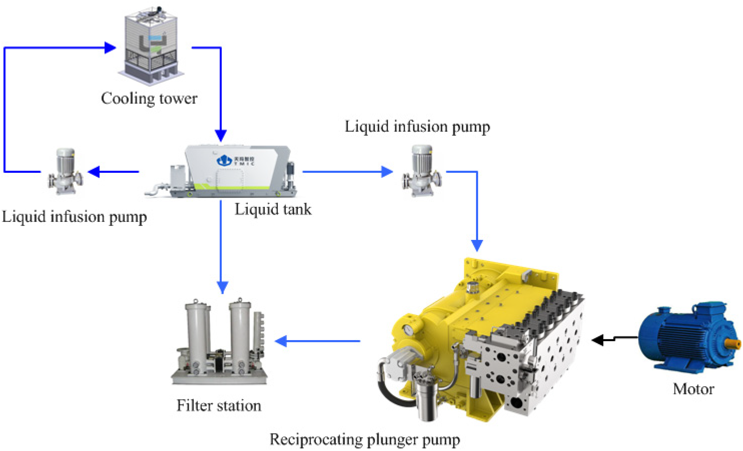
Testing system of reciprocating piston pump.
The reciprocating plunger pump works under the drive of the motor, and the plunger performs reciprocating movement. Correspondingly, the suction and discharge valves open and close regularly to realize the conversion from the mechanical energy of the motor to hydraulic energy. The displacement signals of the pump valve can be obtained by linear variable differential transformer (LVDT) sensor. As shown in Figure 2, the Soway SDVG20 was installed on one of the pump valves to collect displacement signal, and the sampling frequency of the displacement signal is set to 1000 Hz.
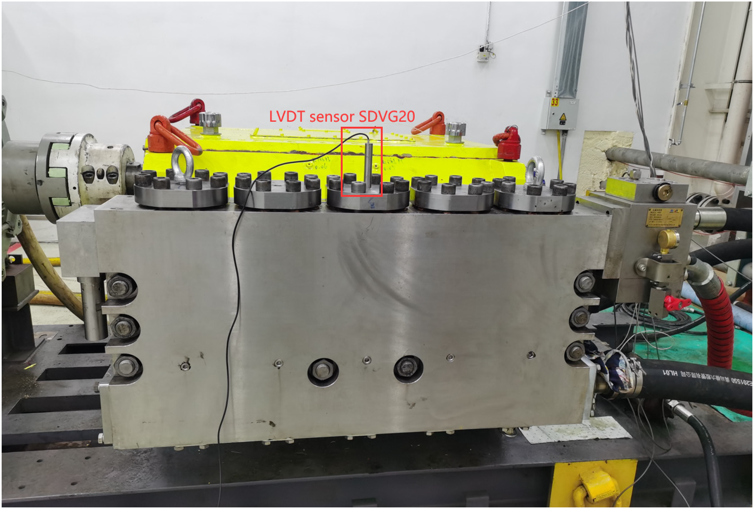
Displacement monitoring of the pump valve based on LVDT sensor.
The technical parameters of the Soway SDVG20 sensor are shown in Table 1.
Technical parameters of the Soway SDVG20 sensor.

Figure 3 schematically illustrates the testing system of the pump valve motion. The velocity and acceleration data can be obtained by derivating the displacement data owing to the high sampling frequency of the LVDT sensor.

Testing system of the pump valve motion.
Data acquisition and analysis
The reciprocating plunger pump valve is mainly used to control the connection or closure between the plunger chamber and the suction chamber or the discharge chamber, and to control the one-way flow of the hydraulic medium. When the plunger moves away from the pump head, the pressure in the plunger chamber decreases. The liquid in the suction tube pushes the valve of the suction valve up, connecting the suction chamber and the plunger chamber, and the plunger pump begins to suck liquid. When the plunger moves for liquid compression, the suction valve spool falls under the combined action of gravity, spring force, and liquid pressure to quickly close the suction valve. The drain valve opens, connecting the plunger cavity and the drain chamber, and the plunger pump begins to drain liquid. The displacement and velocity data under the pump crankshaft speed of 458 rpm and the working pressure of 40 MPa are shown in Figure 4. As shown in Figure 4, the time required for opening the spool fluctuates in a small range, and the maximum speed is around 900 mm/s. In contrast, the spool closing is relatively smooth, with a maximum speed of 250 mm/s.
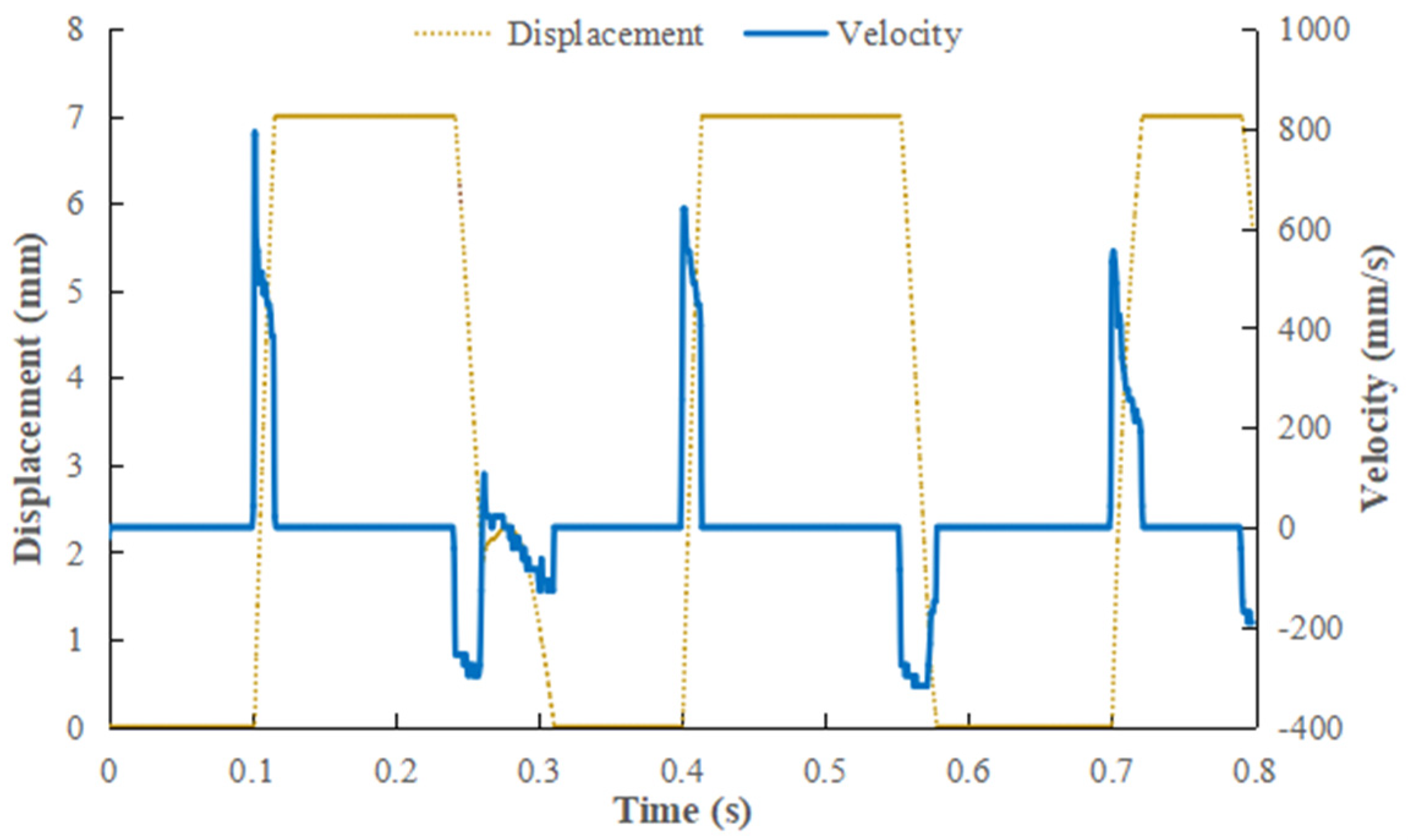
Displacement and velocity of pump valve.
Numerical and analytical analyses of valve dynamic characteristics
To forecast the valve's dynamic behavior, both numerical and analytical methods were used, with AMESim for simulation and U-Adolph theory for analysis. The maximum valve openings were compared using the U-Adolph and AMESim approaches. Meanwhile, the maximum valve closing velocities were compared among different methods under various crankshaft speeds.
Numerical analysis based on AMESim model
The commercial code AMESim, which can simulate the nonlinear motions in a reciprocating piston pump, 20 such as low-speed heavy-duty rotary motion of the crankshaft, reciprocating motion of the connecting rod-crosshead-piston mechanism and nonlinear motion of the pump valves, was used for numerically analyzing the valve dynamic characteristics in this study. A submodel was established to represent the mechanical principle of the dynamic behavior of each piston and pump valve, which consists of an oscillating arm and a translating flat-faced follower component (CFPI00), a piston component (BAP12), a leakage component with variable length, eccentricity, and viscous friction (BAF01) and a mechanical spring and damper component (SD000A). According to the reciprocating plunger pump entity, the corresponding simulation submodel was connected accurately, and the system model of the reciprocating plunger pump was expanded and established. Figure 5 shows the submodel and the system model of the tested reciprocating plunger pump.
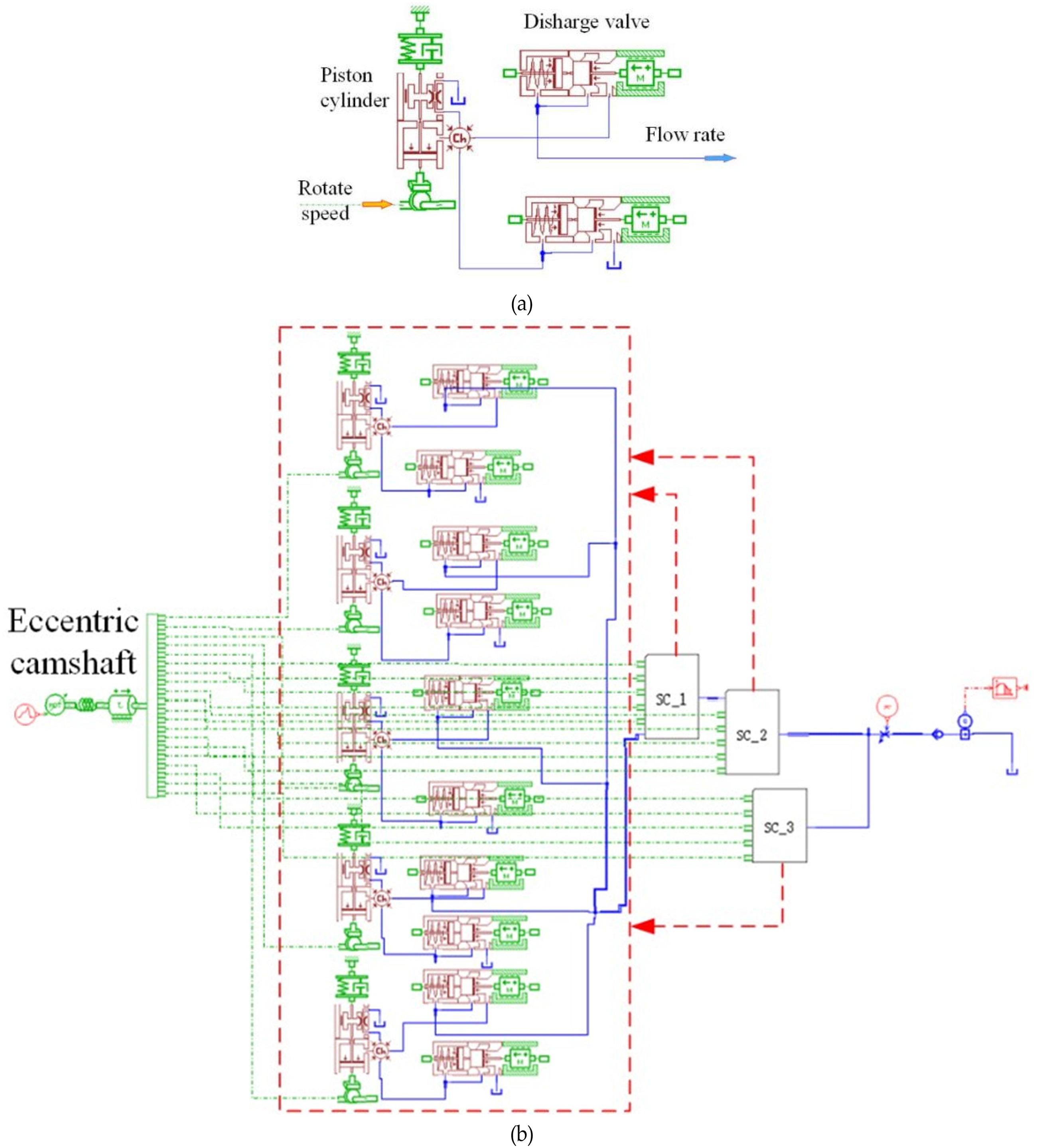
AMESim models: (a) the submodel for representing the distribution mechanism; (b) the entire reciprocating pump.
The main parameters of the AMESim model for the tested reciprocating piston pump are given in Table 2. After the above parameters are set, the dynamic characteristics of the reciprocating piston pump can be simulated.
Parameters of AMESim model.

The working medium is pure water with a density of 1000 kg/m3 and an absolute viscosity of 2.98 × 10⁻³ Pa s. Meanwhile, the bulk modulus of the working medium was set to 16,000 bar. In order to better analyze the influence of the structure parameters of the reciprocating piston pump on its dynamic characteristics, the dynamic influence of the pipeline and accumulator is temporarily ignored in the simulation process, and the operating condition of the system is set as be stable. Figure 6 shows the AMESim predicted valve velocity results for the discharge valve with a spring stiffness of 7000 N/mm and a maximum valve opening of 7 mm.
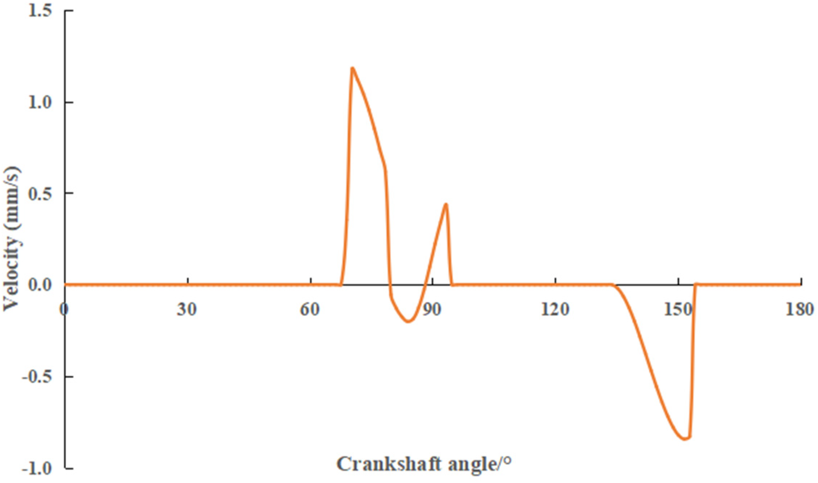
Predicted valve velocity result of AMESim.
U-Adolph exact differential equation
To characterize the dynamic characteristics of the reciprocating pump valve, U-Adolph proposed a second-order nonlinear ordinary differential equation, shown as follows: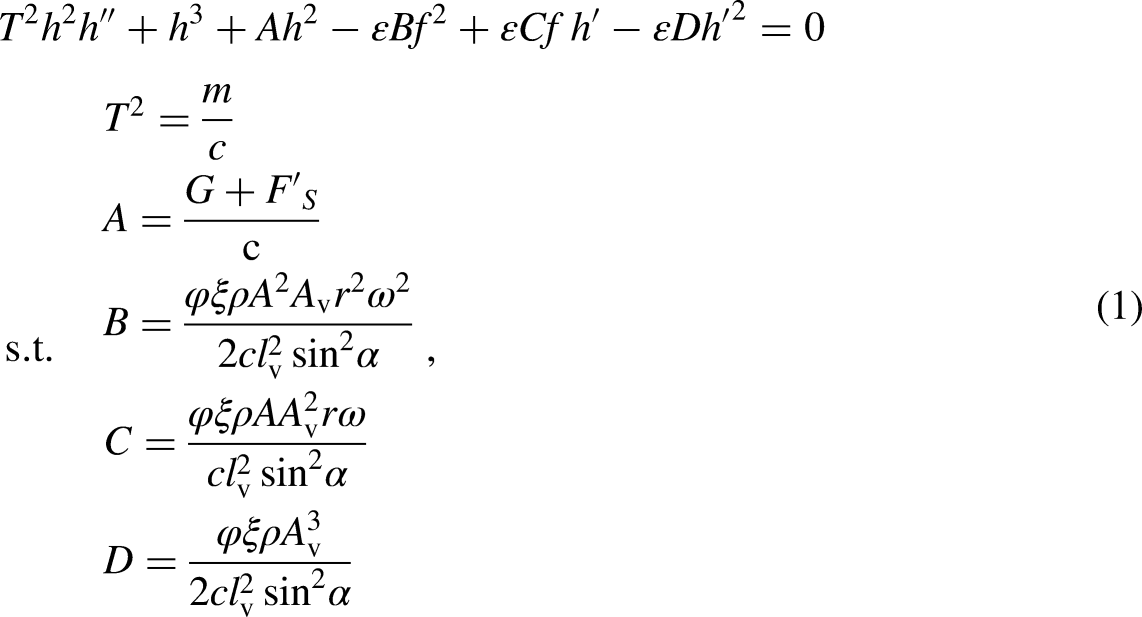
Meanings and values of parameters.

The U-Adolph equation can be solved based on the Runge–Kutta method. It assumes that the valve core opens when the crack angle is 25° and ignores the valve core closing singularity. The method and the solution procedure were reported in detail in a previous study.
Hence, the maximum valve closing velocity and different maximum valve opening under different spring stiffness can be obtained for the tested pump valve. Figure 7 shows a comparison between the AMESim and U-Adolph predicted maximum valve closing velocity versus maximum valve opening results under different spring stiffness.

Predicted maximum valve closing velocity versus maximum valve opening comparison under different spring stiffness.
It can be seen from Figure 7 that the AMESim predicted maximum valve closing velocities are much higher than those obtained from U-Adolph predictions. The U-Adolph predicted maximum valve closing velocities under different maximum valve openings almost remain constant, at a value of 0.2 mm/s. The AMESim predicted maximum valve opening decreases with the increase of the maximum valve opening. For maximum valve opening in the range of 7 mm to 9 mm, the AMESim predicted maximum valve opening decreases with the increase of the spring stiffness. The U-Adolph precise motion differential equation model has singularities during the valve's opening and closing stages, which cannot describe the process of valve opening and closing accurately, leading to a significant difference between analytical results and simulation results.
Finite element analysis of valve impact characteristics
The three-dimensional models of the discharge valve core and valve seat in the tested reciprocating piston pump have been established by the commercial code, Creo and imported into the FE software. FE analyses were performed using ABAQUS, which is used for solving nonlinear problems.21–23 The material used for the discharge valve and seats is 17-4PH, of which the monotonic stress–strain data are given in Figure 8.
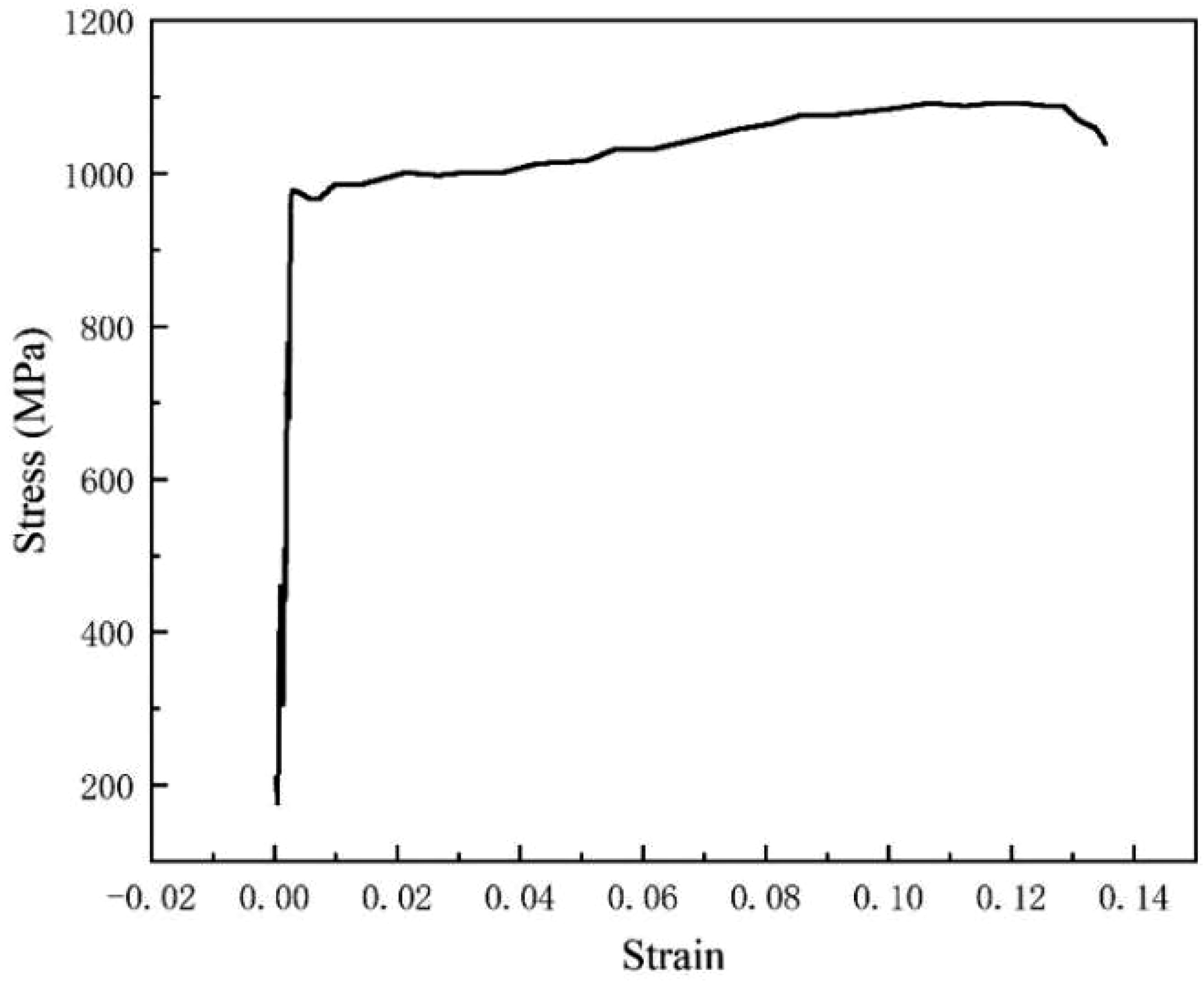
Monotonic stress–strain.
Hence, the Young’s modulus, yielding strength and the plastic strain of 17-4PH can be obtained from Figure 8. The valve core was initially positioned at the maximum valve opening on the top of the valve seat. The velocities of the valve core in the negative y-direction, were applied as the boundary condition, the amplitudes of which were obtained from the AMESim analyses. An encastre boundary condition was applied to a reference point that constrains all the degrees of freedom of the nodes on a surface of the valve seat by using of the kinematic coupling constrain. The ABAQUS/Explicit solver was used to simulate the dynamic process of the discharge valve core closing and impact on the valve seat. The seat was meshed by C3D8R unit, which has good deformation capacity and stress analysis ability, and can ensure high calculation accuracy. The mesh consists of 18,093 nodes and 16,452 elements. Due to the more complex structure of the spool, the C3D10M unit type was used to facilitate meshing, ensuring high calculation accuracy and efficiency. The spool mesh has 16,278 nodes and 10,276 elements. Figure 9 shows a typical mesh for the discharge valve assembly.

Typical mesh for the discharge valve assembly.
Results and discussion
Comparison between numerical and analytical analyses and experimental results for valve motion
Figure 10 shows the experimental results and predicted displacements and velocities obtained from U-Adolph and AMESim approaches at the crankshaft speed of 458 rpm.

The AMESim and U-Adolph predictions comparing with test results for (a) displacements and (b) velocities.
It can be seen in Figure 10(a) that the predicted displacements obtained using the AMESim approach were in good agreement with the experimental results, in terms of the displacement curve shape during valve opening and closing period, the crank angle at the valve opening and closing moments, as well as the maximum valve opening. According to the results of U-Adolph approach, the valve core opens at a crank angle of 25°, reaches a maximum opening of 7.53 mm at 53.4° and the second maximum opening of 6.32 mm at 106°, then drops. The U-Adolph results overpredict the maximum valve opening by 7.6% compared with the experimental result. As shown in Figure 10(b), The U-Adolph and AMESim approaches slightly underpredict the maximum valve opening velocities compared with the experimental result. The predicted maximum valve closing velocity obtained from U-Adolph approach shows good agreement with the experimental result. However, the AMESim predictions overpredict the maximum valve closing velocity.
Figure 11 shows the predicted maximum valve openings obtained from the U-Adolph and AMESim approaches and experimental results under different crankshaft speeds.

The AMESim and U-Adolph predicted maximum valve openings comparing with test results.
As shown in Figure 11, the experimental maximum valve opening remains constant, that is 7 mm, regardless of the change in the crankshaft speed. The U-Adolph and AMESim approaches underestimate the maximum valve openings compared with the experimental results for crankshaft speeds less than 458 rpm. The experimental maximum valve opening and closing velocities, as well as the predictions obtained from the U-Adolph AMESim approaches under different crankshaft speeds, are given in Figure 12.

The AMESim and U-Adolph predicted maximum valve opening and closing velocities comparing with test results.
As can be seen in Figure 12, the experimental maximum valve opening velocities are in a range of 1.1 to 1.6 m/s. The maximum valve opening velocities obtained from the U-Adolph and AMESim approaches increase with the increase in crankshaft speed, but they are still less than the experimental results. The experimental maximum valve closing velocities almost lie between the U-Adolph and AMESim predictions under different crankshaft speeds.
Parameter dependence of impact contact characteristic of valve closing
In order to investigate the effect of structural parameters on the collision contact characteristic of valve closing, a series of FE impact analyses were carried out. The diameter of the valve core and valve seat changed from 45 mm to 60 mm, with a constant bevel angle of 45° and an assumed constant valve closing speed of 0.4 m/s. Figure 13 shows the von Mises stress distributions of impact contacts between the valve cores and valve seats with different diameters. Figure 14 shows the relationship between the maximum von Mises stress and valve diameter.

von Mises stress distributions of impact contacts between the valve cores and valve seats with different diameters.

Relationship between the maximum von Mises stress and valve diameter.
Valve fault simulation and diagnosis
Based on the numerical and simulation analysis of the valve, the design parameters of the valve can be optimized. However, due to the variable operating conditions and complex operating environment of the reciprocating piston pump, valve failure is one of the typical failures of the reciprocating piston pump with high frequency. Based on the above research, the valve fault mechanism is further studied, which provides the mechanism basis for the valve status and even the reciprocating plunger pump status monitoring and fault diagnosis. It guides the reciprocating plunger pump status signal processing, and analyzes the signal characteristics to determine whether the valve fault occurs.
According to the FE analysis of the valve, it can be seen that the cone plane of the valve core will collide with the cone plane of the valve seat, and the force is much larger than at other positions, so the damage is most likely to lead to valve failure. As shown in Figure 15, serious damage occurs at the simulated valve. Due to the damage to the spool cone plane, the vibration response generated when the valve opens or closes will inevitably change accordingly, which can be used as an important basis for judging the valve state.
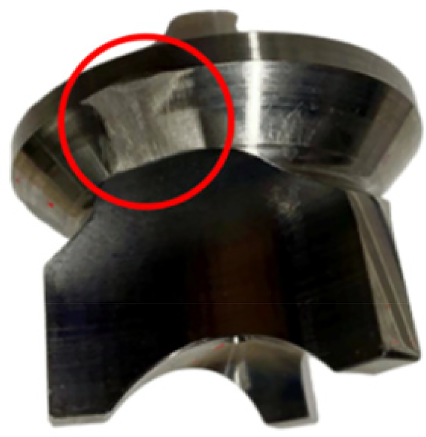
Damaged spool.
As shown in Figure 16, vibration acceleration sensors were used to collect the shock response of the pump head during valve operation to characterize the health state of the valve. At the same time, a phase sensor was installed on the crankcase to obtain the crankshaft angle corresponding to the valve.

Vibration and phase monitoring of reciprocating piston pump.
The vibration signal of the pump valve and the phase signal of the crankshaft were collected by a data acquisition device, and the vibration and phase signals are shown in Figure 17.

Vibration and phase signals.
According to the structure and working principle of the reciprocating piston pump, the phase of the crankshaft corresponding to the opening time of the valve can be determined, and then the corresponding vibration signal can be determined. Before the valve is fully opened, the influence of spool damage on the vibration state of the valve is bound to exist. Based on the above simulation study, the corresponding crankshaft angle can be determined to be 25°. The vibration signals under normal valve conditions and spool wear failure are shown in Figure 18. It can be seen from the figure that the amplitude of vibration and shock in the damaged state of the valve core is much larger than that in the normal state.

Comparison of vibration signals in different states.
Based on the above analysis, the vibration signal is analyzed in combination with the key signal. The vibration signal during the opening of the valve is intercepted, and the root-mean-square (RMS) characteristics of the signal are calculated. The definition of RMS is shown as follows:
Taking the crankshaft rotation of 360° as a period, the RMS characteristic values of vibration signals under two different states were compared, and the results are shown in Figure 19. As can be seen from the figure, when the valve spool is worn, the vibration energy at the opening time of the valve will be significantly larger. According to this, it can be judged that the valve is faulty and should be stopped for maintenance and replacement in a timely manner.

Comparison of vibration characteristics in different states.
Conclusions
Experimental and numerical study on valve dynamic and impact contact characteristics of a quintuple reciprocating piston pump were carried out in this study. The dynamic characteristics of the reciprocating pump valve were experimentally investigated by performing the valve motion tests. The test results were compared with the AMESim and U-Adolph predictions. The concluding remarks are shown as follows:
For different spring stiffness values, the maximum valve closing velocities predicted by AMESim are much higher than those obtained from the U-Adolph predictions. The maximum valve opening velocities predicted by AMESim decrease with the increase in spring stiffness, while the maximum valve closing velocities predicted by U-Adolph under different spring stiffness values almost remain constant, at a value of 0.2 mm/s. The U-Adolph and AMESim approaches underestimate the maximum valve openings compared with the experimental results, which are almost constant at 7 mm for crankshaft speeds below 458 rpm. For different crankshaft speeds, the experimental maximum valve opening velocities are larger than the predictions made by both U-Adolph and AMESim, and the experimental maximum valve closing velocities almost lie between the predictions of U-Adolph and AMESim. A series of FE analyses, using the commercial code, ABAQUS, were performed for investigating the valve closing impact contact stress between the valve cores and valve seats with different diameters. The FE results show that the maximum von Mises stress increases from 431 MPa to an approximate constant value of 590 MPa with the enlargement of the valve diameter. Combined with simulation and experimental research, a fault diagnosis method for valve is proposed. The accurate diagnosis of valve faults can be realized by intercepting the vibration signal during valve opening and extracting the RMS feature. The effectiveness of the method has been verified by experiments.
Footnotes
Declaration of conflicting interests
The authors declared no potential conflicts of interest with respect to the research, authorship, and/or publication of this article.
Funding
The authors disclosed receipt of the following financial support for the research, authorship, and/or publication of this article: This work was supported by the China Coal Technology Engineering Group (grant numbers 2023-TD-QN004 and 2023-TD-QN006).