
Abstract
In this paper, a cylinder contact model with different axis crossing angles is proposed, and the axis crossing angle is introduced into the normal and tangential constitutive equations. This paper uses the method of formula derivation to establish the analytical solution of the tangential elastic contact of the cylinder with different axis cross angles, and gives the relational expression of the tangential load and the tangential displacement. The finite element method (FEM) is used to verify the tangential displacement load curve and the tangential stiffness curve of the two cylinders. The influence of various factors on mechanical properties such as tangential stiffness, tangential displacement and contact area is explored, and the distribution of stress and strain on the contact surface is analyzed. The research results show that the tangential displacement and tangential stiffness of the cylindrical contact model correspond well to the simulation results.
Keywords
Introduction
Contact mechanics is widely used in all aspects of the mechanical field. The force transmission of each part in the machine is always realized through the contact between the two parts. For example, mechanical joint surfaces, rolling bearings, gear meshing, cam contact, car tires and ground contact, etc. The contact between the individual asperities between the bonding surfaces. Generally speaking, the contact surface of this type of contact is not flat, the contact area is very small, and a large contact stress will be generated, which will cause the deformation of the contact position. Regardless of whether it is the macroscopic contact problem between mechanical parts or the microscopic contact problem of a single micro convex body on the joint surface, corresponding contact models have been proposed to study them, but some contact models involving angles have not yet been modeled.
Hertz 1 first linked the force acting on the contact model with the contact area and deformation in the late 19th century. And put forward a hypothesis to solve the Hertz contact problem, pointing out that the contact surface is elliptical. On this basis, subsequent researchers applied it to solve macro and micro contact problems on the basis of their own research, among which the sphere model is the most classic. Then Johnson 2 gave the expressions of the contact radius and contact deformation of the circular contact, as well as the half-bandwidth and maximum contact pressure of two parallel cylinders. Some researchers have proposed a spherical contact model and deduced an analytical solution for its deformation. Including the indentation model of rigid sphere and elastic plane by Ghaednia et al., 3 the flattening model of elastic sphere and rigid plane by Chang et al. 4 and Kogut et al. 5 and the contact model of two elastic spheres.6–8 Most researchers conduct research based on fractal theory, such as the G-W model based on statistical analysis 9 and the M-B model based on fractal theory. 10 Although this type of research can correspond well to the results, it is a problem for the repeatability of the experiment.
In recent studies, some researchers have used the cylindrical contact model. Çömez 11 considered the frictional movement contact between the conductive rigid cylindrical punch and the piezoelectric material layer. Zhang et al. 12 studied the mathematical model, tooth contact analysis and stress analysis of curved cylindrical gears with line contact. The contact and bending stresses of curved cylindrical gears with and without tooth tip backlash are discussed by the FEM. Jana et al. 13 studied the contact between a semi-cylinder and a rigid plane based on the finite element, introduced and discussed the contact area, contact force, and contact pressure of the semi-cylinder. Sugunesh et al. 14 used Ansys to analyze the contact stress behavior of two cylinders, conducted an initial convergence study to obtain the best mesh and compared with theoretical values. Yongqiao et al. 15 studied the calculation formula for the maximum contact stress of cylindrical gears based on the Hertz formula. The contact stress calculation formula especially considers the influence of the normal force, the total bearing length, the comprehensive radius of curvature and the position angle. Huaidong et al. 16 used two-dimensional plane strain finite element analysis (FEA) to study the unidirectional sliding contact between a deformable semi-cylinder and a deformable flat block. One-way sliding is controlled by displacement control, and junction growth has also been studied, indicating that the growth direction is the same as the direction of the tangential force experienced by the weaker material. Honghai et al. 17 proposed the first fractal model of the loading and unloading process between two cylindrical surfaces with friction. The nonlinear relationship between the actual contact area and the contact load at different deformation stages in a loading and unloading cycle is derived. Çömez et al. 18 considered the frictional movement contact problem of an orthotropic layer bonded to an isotropic half-plane under the action of a sliding rigid cylindrical punch. The boundary conditions of this problem include the normal force and tangential force exerted on the layer, and the cylindrical punch moves laterally on the surface of the layer at a constant speed. Yang et al. 19 studied the fretting wear between a deformable half-cylinder and a deformable flat block based on the FEM. An empirical formula for the initial total slip distance is constructed, which once again reveals the results that are very consistent with the results obtained from the finite element for different materials and various scales. Aman et al. 20 proposed a finite element study of elastoplastic cylindrical contact. The geometric shape can also be described as a vertically aligned disk whose axis of symmetry is parallel to the contact surface. The cylinder is considered to be in a state of plane stress. Compare the finite element results of elastic and fully plastic cylindrical contact with other existing models (such as Hertzian contact and spherical elastic-plastic models). Jorge et al. 21 studied the multi-body dynamics method driven by a roller chain and used a cylindrical contact model. And it is proved by studying the dynamics of roller chain transmission with different initial preload and energy dissipation coefficient. Pereira et al. 22 proposed an alternative analytical cylindrical contact force model, which described the contact force as an explicit function of penetration. The new enhanced cylindrical contact force model is based on the Johnson contact model and complementary FEA for internal and external cylindrical contact. Hongping et al. 23 aimed to propose a normal and tangential contact stiffness model. Based on fractal geometry and contact mechanics theory considering the interaction of surface roughness, the contact characteristics between rough surfaces of machined joints were studied.
For the contact strain problem of two parallel cylinder models, Cattaneo 24 and Mindlin 25 pointed out in their research that the contact area of two parallel cylinders is a rectangular area. After the tangential load is applied, a central stick area is generated, and there are two slip areas around it. However, only the contact model of two parallel cylinders is analyzed, and the contact model under different axis crossing angles is not analyzed. In our previous works, Guo et al.25,26 proposed a cylindrical and cosine wave contact model with different axis crossing angles. The analysis of the relative mechanical characteristics of normal contact is proposed, but the tangential relative theory is not deduced.
Hertz 1 first proposed the contact problem and its analytical solution. He derives the analytical solution for the elastic phase of cylindrical geometry, which is very famous. Both Johnson 2 and Hamrock 27 provided clear solutions in their papers. Most of the cylinder deformation is studied based on finite element, especially some cylinder-plane contact models, 28 analytic solution equations are rarely used to accurately describe this process, because the change process of this process is extremely complicated. However, for the single-peak contact problem of the cylinder, only the contact of two parallel cylinders is considered. At this stage, the contact problem of the two cylinders under different axis crossing angles has not been studied. Jinyuan 29 proposed a series of regular elastic sphere contact models under uniform normal load and tangential load at the same time. Diego 30 proposed a cross-cylinder contact model. Most of the models realized by the above-mentioned researchers are based on fractal theory. Most of the contact area is qualitative analysis, and there is no specific quantitative expression. At the same time, it did not study the influence of the axis crossing angle on the model.
Therefore, based on the Hertzian contact theory, this paper establishes a cylindrical contact model under different axis crossing angles. The relational expression of tangential load and tangential displacement and the expression formula of tangential stiffness are deduced and verified by finite element. The influence trends of various influencing factors on the mechanical properties are further studied.
Cylinder normal contact model
In various mechanical parts, the transmission of force is always realized by contact. For example, macro-contact problems such as gear and bearing contact, or micro-contact problems such as micro-protrusion contact on the joint surface. In addition, the two-contact model has certain angular contact problems during the contact process.
Therefore, based on such problems, this paper introduces the axis crossing angle into the constitutive equation of the contact model. A cylinder elastic contact model with different axis crossing angles is established. When the axis crossing angle is 0 degrees, the contact model of the two cylinders is shown in Figure 1.(a). When the axis crossing angle is changed, the contact model of the two cylinders is shown in Figure 1.(b). As shown in Figure 1.(c), Guo et al. 31 proposed a cosine wave model that considers the axis crossing angle. The elastic-plastic contact properties of the contact model in the normal direction are studied.

Contact model: (a) parallel cylinder model, (b) crossed cylinder model, and (c) crossed cosine model.
When a normal load P is applied to the contact model of two cylinders, the contact model will generate a corresponding normal displacement


The state of the contact model under normal load: (a) no normal load; and (b) normal load.
Considering the initial gap h between any two points on the surface of the cylinder, the distance at which any two points on the contact surface converge to each other, L, can be expressed as:


Schematic diagram of a contact surface relationship,
By integrating Eq. (3) and combining Eq. (2) with Eq. (3), the relationship between the normal displacement

Where
The eccentricity of the contact ellipse can be obtained according to Eq. (6) ,
26
where

Critical mean contact pressure at which yielding of the contact model starts can be expressed as
32
:

The equation for the C-value is given by Green
32
:


When the normal load P continues to increase, the normal displacement continues to increase as well. Then, the contact model enters the plastic phase. According to indentation tests ,
33
when the contact model enters the plastic phase, the critical average pressure


In the process of tangential load affecting Hertzian contact, in order to simplify the analysis process, avoid excessive coupling of the contact area. Now make the following simplified assumptions for the contact model: using the same material, the normal load does not produce displacement in the tangential direction, and the tangential load does not produce displacement in the normal direction. This greatly simplifies the analysis process. In this way, when there is no tangential load and only normal load, the contact model will not slip regardless of whether there is friction between the contact models.
Assuming that the radius of the cylinder is R and the material is the same, it is only a point contact before being loaded. After the normal load P is applied, the shape of the contact surface is ellipse, and the cylinder produces a normal displacement

Contact state of the loaded cylinder: (a) only normal load, and (b) normal load and tangential load,
The displacement of the contact surface of the two cylinders is
2
:

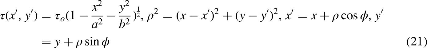
According to Figure 3 and the polar coordinate method for solving the double integral, Eq. (20) can be rewritten as:


The combined contact problem when the tangential load and the normal load are applied is discussed. For example, it can be imagined that two cylinders contact models are squeezed together under the action of the normal load P. Then, a force F is applied along the tangential direction. Assuming dry friction exists between two cylinders contact models, according to the simplest form of Coulomb's law of friction, the maximum static friction stress


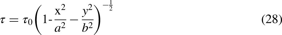
Based on Eq. (27), normal stress at the boundary is close to 0 and the tangential stress approaches infinity. Thus, the contact boundary can never satisfy

The non-sliding zone and the sliding zone in tangential contact,
The c is the major axis of the contact small ellipse, the parameter d is the minor axis of the contact small ellipse.
a can be expressed as:
Parameter b can be expressed as:
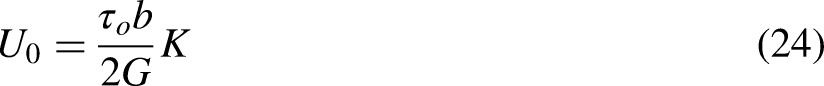
Therefore, according to


Parameter p0 is substituted into Eq. (34), which is then expressed as:


The tangential elastic contact stiffness is equal to


This paper establishes a cylindrical contact model under different axis crossing angles, and considers the influence of normal load and tangential load on the contact model. The software ABAQUS is used for FEA. In order to save calculation time, a half circle is used to create a cylinder. The upper and lower cylinders contact models have the same shape and size, and the radius R is 5 mm. As shown in Figure 6, a model with different axis crossing angles of 45°, 60°, and 90° was established. Explore the influence of different axis crossing angles on contact mechanics characteristics.

Finite element contact model with different axis crossing angles: (a) 45 degrees, (b) 60 degrees, and (c) 90 degrees,
The main steps of the FEA of the cylindrical model are as follows. First, material properties are created and ABAQUS is used to assign material properties to the cylindrical model. Model properties are created and edited through the property module, including material properties such as density, elasticity, and plasticity. Finally, material and model properties are respectively assigned to the cylindrical model. The specific material parameters are shown in Table 1.
Model material properties.

In ABAQUS, analysis steps are divided into two categories: general analysis steps and linear perturbation analysis steps. The former is used for linear and nonlinear analysis, and the latter can only be used for linear analysis. In this paper, a nonlinear analysis of statics is required. Therefore, a general analysis step is used. In the general analysis step, “Static, General” type is selected, as shown in Figure 7. In the basic tab, geometric nonlinearity (NLGEOM) is turned on. In the incrementation tab, the increment type is set to “Automatic”, the maximum increment step to 100, the initial increment size to 0.01, and default mode is used for the remaining options.

Analysis step settings,
Next, contact and coupling points are defined according to the following. Since the objects analyzed in this paper are all contact models, a reasonable contact surface needs to be set. Contact based on contact or surface elements represents two basic contact types of ABAQUS. Since surface contact is a widely used type, it is also employed in this paper. Tangential mechanical behavior is chosen, and the friction coefficient is set to 0.2. Considering that a concentrated force needs to be applied in the load setting, a coupling point has to be created to couple the node where the load needs to be applied to a single point. A coupling point is established at the center of the upper plane of the upper cylinder model. Normal load P and tangential load F act on this coupling point.
The lower cylinder model is fixed in its lower plane, i.e. six degrees of freedom of the nodes in the lower plane of the lower cylinder model are fixed. Nodes in the upper plane of the upper cylinder model allow normal and tangential degrees of freedom, while the remaining four degrees of freedom are fixed. Boundary conditions of the contact model are shown in Figure 8. The load is applied using concentrated force. Since the coupling point is in advance as described in the aforementioned steps, it is only necessary to select the concentrated force method in the load module. Then, the normal load P and the tangential load F are applied the coupling point.
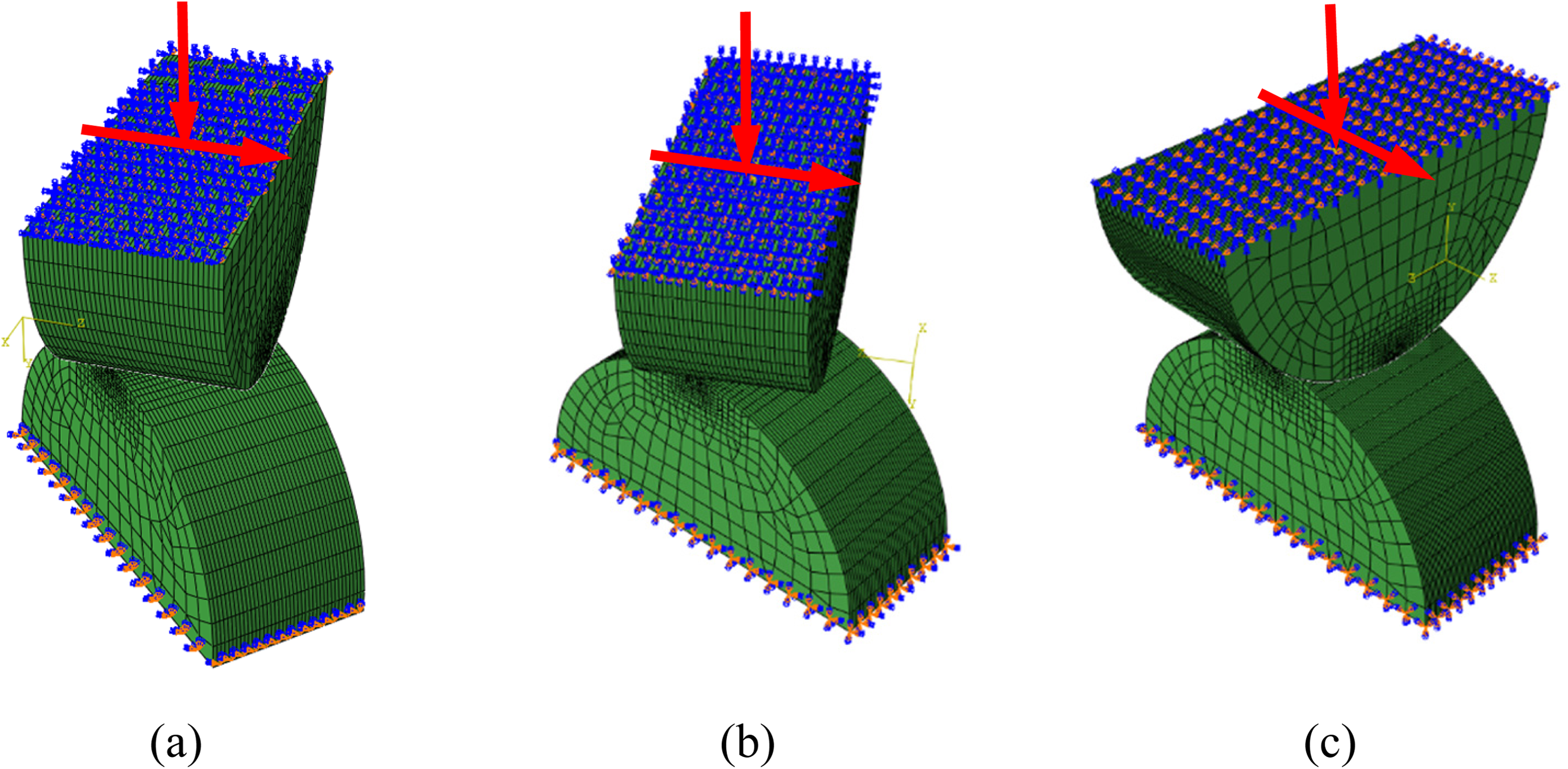
Schematic diagram of contact model restraint and load action: (a) 45 degrees, (b) 60 degrees, and (c) 90 degrees,
The element type used is designated in ABAQUS as C3D8R, the number of elements is 250 000 with the corresponding number of nodes being 2 659 682. The mesh of the contact parts is shown in Figure 9.

Local mesh refinement results: (a) The overall schematic diagram of the contact grid, and (b) The local schematic diagram of the contact grid.
Tangential displacement and tangential stiffness
A normal load of 20 N is applied to the upper cylindrical model followed by the application of the tangential load. To ensure that the contact model does not slide, normal and tangential loads are in a cohesive state and no sliding occurs when the above relationship is satisfied. This is in accordance with Coulomb's law of friction described in Eq. (26).
According to the material properties and parameter settings in Section 4 above, the contact model is submitted to the FEA, and the FEA results are obtained. The displacement of the contact area of the upper cylinder model and the tangential displacement of the contact area of the lower cylinder model are added to obtain the FEA value. The FEA value and the analytical solution are compared and analyzed to obtain the comparison result, as shown in Figure 10.

Comparison of tangential displacement analytical solution and FEA value: (a) 45 degrees, (b) 60 degrees, and (c) 90 degrees.
According to Figure 10, the FEA result of tangential displacement corresponds well to the analytical solution provided by Eq. (36). Under the condition of keeping the normal load and the axis crossing angle constant, the tangential displacement and the tangential load are nonlinear. As the tangential load increases, the tangential displacement also gradually increases, and the increasing speed becomes faster and faster. While keeping other variables constant, the increase of the axis crossing angle will lead to an increase in the tangential displacement, which further shows that the increase of the axis crossing angle will cause a decrease in the tangential stiffness.
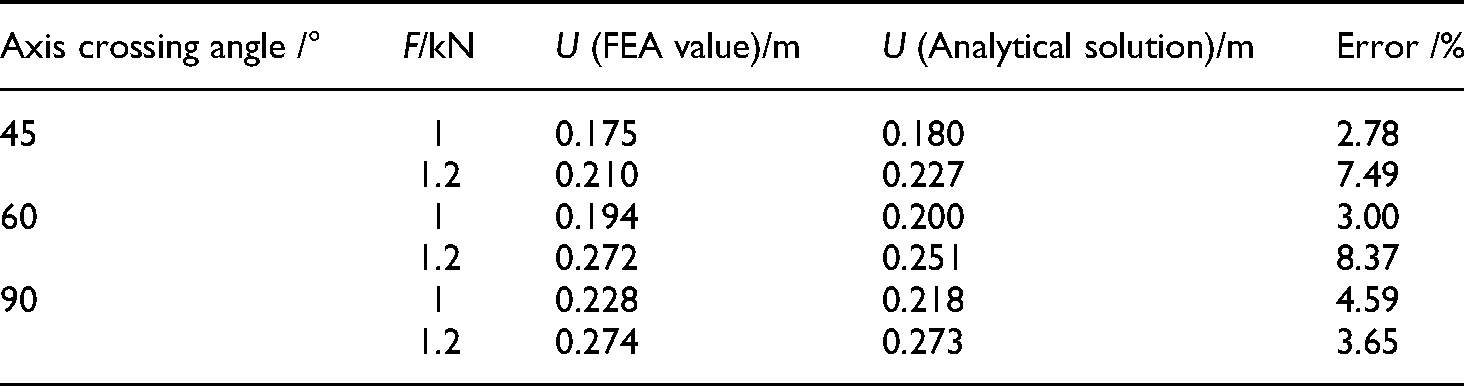
Under the premise of a normal load of 20 kN, different tangential loads are applied to the two cylinders contact models with different axis crossing angles. There is a certain error between the analytical solution and the FEA value. As shown in Table 2, the maximum error is 8.37%. The minimum error is 2.78%.
Comparison of tangential displacement FEA value and analytical solution.
In FEA, the tangential contact stiffness can be obtained from displacement and deformation. After getting the discrete points of the tangential displacement. Curve fitting is used to fit the finite element tangential displacement curve. Differentiate the tangential displacement curve to obtain the tangential stiffness curve. The comparison between the tangential stiffness of the cylindrical contact model and the FEA result is shown in Figure 11 below.

Comparison of tangential stiffness analytical solution and finite element analysis value: (a) 45 degrees, (b) 60 degrees, and (c) 90 degrees.
It can be seen from the figure that the stiffness obtained by the FEA corresponds well to the stiffness analytical solution provided by equation (38). The increase of the tangential load will reduce the tangential contact stiffness. The tangential contact stiffness decreases faster and faster with the gradual increase of the tangential load. When other conditions remain unchanged, the increase of the axis crossing angle will cause the decrease of the tangential contact stiffness.
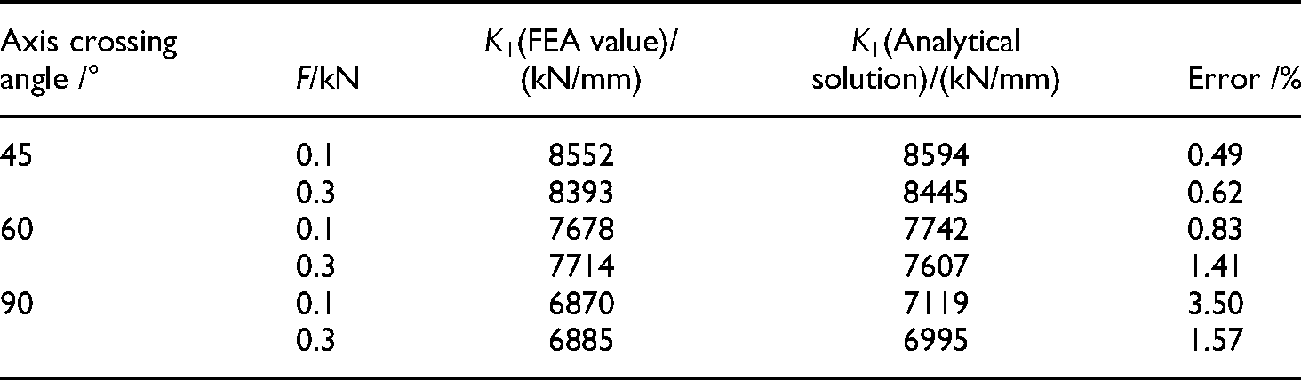
Different tangential loads are applied to the contact model of two cylinders with different axis crossing angles, and there is a certain error in the analytical solution and the FEA value. As shown in Table 3, the maximum error value is 3.50%, and the smallest error value is 0.49%.
Comparison of FEA values and analytical solutions of tangential contact stiffness.
The cylindrical tangential displacement includes two parts: the tangential displacement of the contact surface and the displacement of the cylindrical entity. In order to understand the influence of the cylinder body displacement on the overall displacement, this section compares the tangential displacement of the contact surface with the overall displacement. The finite element model is as mentioned above. Under a normal load of 20 kN, the overall displacement and tangential displacement of the contact surface of the two cylinders with different axis crossing angles are shown in Table 4.
Comparison of the overall displacement of the cylinder and the tangential displacement of the contact surface.

Comparison of the overall displacement of the cylinder and the tangential displacement of the contact surface.
The overall tangential displacement is not much different from the tangential displacement of the contact surface, with a maximum difference of 3.42%. The tangential displacement is mainly reflected in the deformation of the contact surface, and the cylindrical entity has little effect on the tangential displacement. In the analysis of the overall tangential displacement of the cylindrical contact, the tangential displacement of the solid part can basically be ignored.
A 90° cylinder contact model is used as an example in this section. A normal load of 20 kN is applied to the contact model, while different magnitudes of tangential loads are employed. The distribution laws of stress and strain on the contact surface of two cylinders contact models, as well as the development of the stress form and adhesion zone in the contact region, are studied. Moreover, the shape of the contact region under different axial crossing angles is demonstrated.
According to theoretical investigations, stress distribution should be symmetric with respect to the contact surface before the tangential load is applied. However, after the tangential load is applied to the contact model, the stress distribution becomes asymmetric. According to Figures 12 and 13, the shear stresses and von Mises stresses distributed on the contact surface become asymmetric. On the other hand, maximum shear stresses and von Mises stresses do not appear at the symmetry axis but near it. Lastly, the peak stresses increase with a gradual increase in the tangential load.
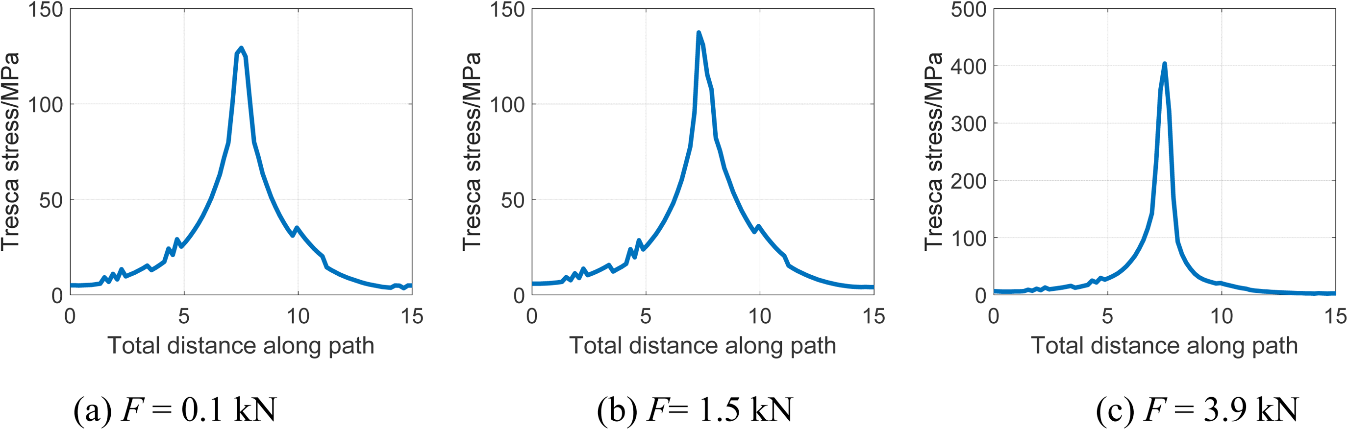
Tresca stress distribution on the contact surface under tangential load (P = 20 kN).

Mises stress distribution on the contact surface under tangential load (P = 20 kN).
Similarly, from the von Mises stress profile view of two cylinder contact models in Figure 14, the maximum value of the contact stress appears below the contact surface under the preload of the normal load. This indicates that the yielding is reached first below the contact surface and then moves towards it to cover the entire surface. According to Figure 14, the tangential load gradually increases, and the von Mises stress distribution increasingly deviates from the symmetry axis. Based on the results presented in Figure 15, as the tangential load gradually increases from both sides towards the middle, the maximum contact stress shifts from below the contact surface to the surface. With a further increase in the tangential load, the elastic region disappears. At this time, the tangential load exceeds the maximum static friction, and the contact model begins to slide.

Mises stress distribution cloud diagram of two contact models under tangential load (unit: MPa; P = 20 kN).

Development history of contact area under tangential load (unit: MPa; P = 20 kN).
The maximum strain is symmetrical before the application of tangential loading and asymmetrical after the application of tangential loading. The maximum strain has a peak at the edge of the contact area, and a larger peak at the leading edge is subjected to tangential loading. As shown in Figures 16 and 17, under normal load preload, the strain and displacement on the contact surface are also asymmetrical. It is influenced by tangential loading, with peaks appearing near the axis of symmetry and increasing with the tangential load. This occurs because the upper cylinder model is obtained. An upper cylinder model is a stressed object, which naturally produces the adhesion zone with the lower cylinder model in the contact area. This makes the contact area slightly smaller than the overall displacement, while the displacement in the contact area gradually increases with an increase in the tangential load. During the gradual increase in the tangential load, there is always a slip at the boundary due to the boundary conditions shown in Eq. (27) and Eq. (28). As the tangential load increases, the slip zone gradually increases and the adhesion zone gradually decreases, as shown in Figure 18.

Strain distribution law of contact surface under tangential load (P = 20 kN).

The distribution law of tangential displacement of the contact surface under tangential load (P = 20 kN).

Contact area change diagram under tangential load (unit: mm; P = 20 kN).
The FEA is performed based on the above parameter settings, and the FEA results are obtained. Figure 19 shows the local displacement and deformation cloud diagram of the contact surface area of the cylindrical contact model with the axis crossing angles of 45°, 60°, and 90°. It can be seen from the figure that when the axis crossing angle is 45°, 60°, the shape of the contact surface is an ellipse. When the axis intersection angle is 90°, the shape of the contact surface is circular, as shown in Figure 19.(c), at this time the eccentricity is 0, which is consistent with the theoretical analysis above.

Displacement cloud map of the contact area under different axis crossing angles (unit: mm): (a) 45 degrees; (b) 60 degrees; (c) 90 degrees.
The tangential displacement curve and tangential stiffness curve of the cylinder are very different from the finite element analysis results, and the analytical solution can reflect the contact mechanical characteristics of the two cylinders. This section explores the influence of different factors on the mechanical properties of cylindrical tangential contact.
Under the above-mentioned material properties and basic parameter settings, the influencing factors of the contact area and tangential stiffness of the two-cylinder contact model and the tangential displacement are analyzed. Including the influence trend of the axis crossing angle, radius, friction factor and normal load on the above three.
According to the presented figures, the relationship between various influencing factors and mechanical properties can be classified as exponential. As the shape parameter of the contact model, the radius is crucial in the derivation of the analytical solution of the entire contact model.
In Figure 20, it can be seen that the radius has an effect on the tangential displacement, contact area and tangential stiffness. As the radius increases, the tangential displacement tends to decrease, and the contact area and tangential stiffness tend to increase. An increase in the radius means an increase in the contact model. The same force acts on a model with greater stiffness, and the displacement is bound to decrease. But for a contact model with a larger radius and increased stiffness, the contact area becomes larger, as shown in Figure 19.(a), which is contrary to conventional thinking. This problem is also found in the BKE model studied by Brizmer et al. 37 and the KE model investigated by Kogut et al. 5 The explanation given by Aizhong et al. 38 is that the presence of tangential load at the fixed normal load causes coupling of many quantities at the contact surface, which in turn increases the overall contact area. Their qualitative explanation suggests that this may be due to the reduction in the normal load-bearing capacity of the material after plastic deformation. The contact area must be increased to reduce the contact pressure and adapt to the ever-increasing tangential stress. Simultaneously, a fixed equivalent von Mises stress has to be maintained. This Mises stress is equal to the material yield strength in the plastic deformation region. It should be noted that the growth of the contact area was also theoretically reported by Brizmer et al., 37 who attributed the growth of this junction to an increase in the normal contact disturbance during tangential loading. Ovcharenko et al. 39 compared their experiments with the model of Brizmer et al. 37 The authors found the result to be consistent at high normal loads. Cohen et al. 40 further investigated smooth spheres in contact with rough planes. They found that roughness effects could explain the differences between the results from 37 and 39 The aforementioned investigations assumed a constant normal force during tangential loading. However, even when a fixed normal displacement loading is applied (as is the case in this paper), the contact area increases with tangential loading. This indicates that the mechanism of the contact area growth may be more complex. An increase in the contact area is mainly due to the elastic recovery of the sphere material outside the original contact area during tangential loading. Thus, a new contact area is formed. Under local slip conditions, an increase in the contact area originates from two parts: one is the elastic recovery of the spherical material outside the original contact area, and the other one is the plastic flow of the material within the original contact area.
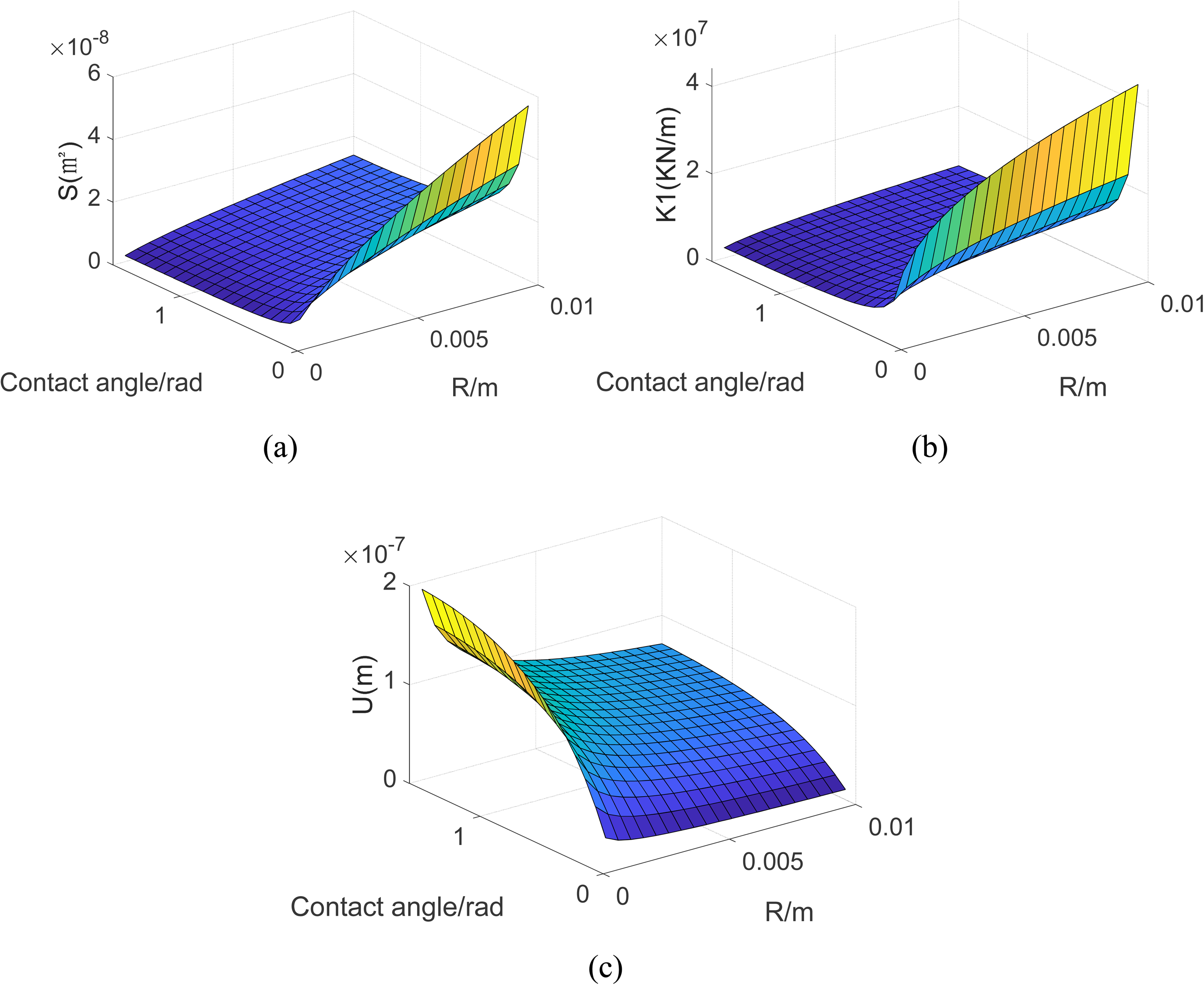
Effect of radius on mechanical properties: (a) contact area, (b) tangential stiffness, and (c) tangential displacement.
Figure 21 shows the influence of the friction factor of the contact surface on the mechanical properties. It can be seen from the figure that, like the radius, the friction factor will also have a certain impact on the mechanical properties. The specific manifestation is that the increase of the friction factor causes the decrease of the tangential displacement, the increase of the contact area and the tangential stiffness, and the friction factor has an exponential function relationship with them.
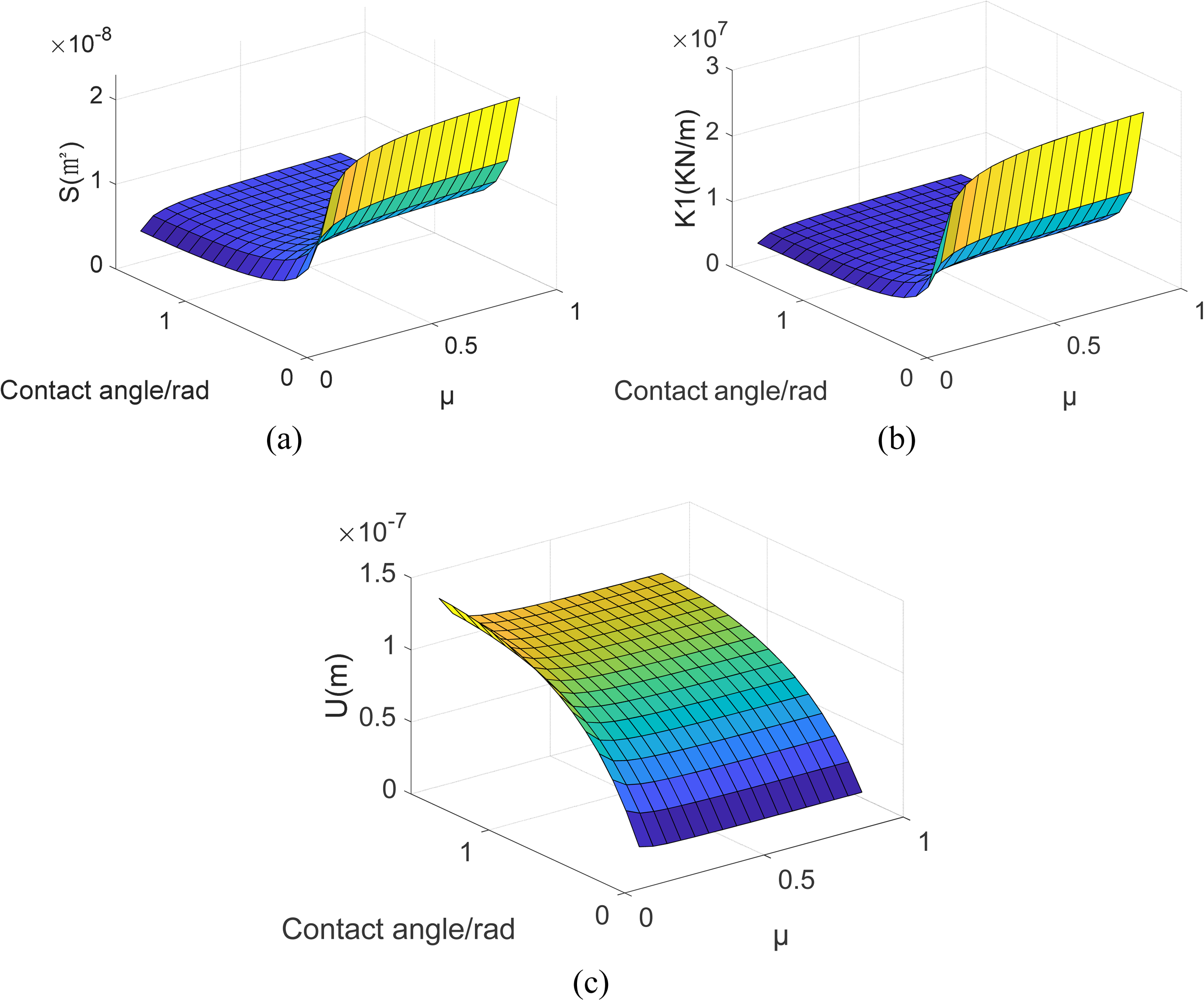
The influence of friction factor on mechanical properties: (a) contact area, (b) tangential stiffness, and (c) tangential displacement.
Figure 22. shows the influence trend of the normal load P on the mechanical properties during the contact process: the increase of the normal load causes the decrease of the tangential displacement, the contact area and the tangential stiffness increase, and they have an exponential relationship.

The influence of normal load on mechanical properties: (a) contact area, (b) tangential stiffness, and (c) tangential displacement.
During the entire contact process, the axis crossing angle of the two cylinders in contact with the model will also affect the mechanical properties. It can be clearly seen that as the axis crossing angle of the contact model increases, the tangential stiffness decreases, and the corresponding tangential displacement increases. Similarly, with the increase of the axis crossing angle, the contact area will change from the original rectangular contact to the elliptical contact, and the contact area will decrease, which will increase the stress on the contact surface and increase the displacement of the contact surface.
This paper proposes a cylindrical tangential elastic contact model with different axis crossing angles. Through theoretical derivation, the axis crossing angle is introduced into the constitutive equation of the cylindrical tangential elastic contact model. The tangential displacement curve and tangent stiffness curve of the cylinder under different axis crossing angles are established, and the FEA is used to verify them. The influence of the cylindrical body deformation on the tangential deformation is analyzed: the tangential displacement of the cylindrical contact model includes two parts: the sliding of the contact surface and the displacement of the cylindrical body. The cylindrical body has a small influence on the tangential displacement and can be ignored. The change law of stress and strain on the contact surface is studied: with the gradual increase of the tangential load, the peak stress and strain that originally appeared at the axis of symmetry appears near the axis of symmetry. On this basis, the mechanical properties of the cylindrical tangential contact are obtained: the tangential stiffness of the cylindrical asperity is a complex nonlinear function relationship between the normal load P and the tangential load F acting on the cylinder. The normal load P and the tangential load F have a nonlinear relationship with the tangential contact stiffness of the cylindrical contact model. With the increase of normal load, the contact area and tangential stiffness tend to increase, and the tangential displacement tends to decrease. The increase of the friction factor will cause the contact area and tangential stiffness to increase, and cause the tangential displacement to decrease. As the radius becomes larger, the contact area and tangential stiffness increase, and the tangential displacement decreases. The contact area and tangential stiffness will decrease with the increase of the axial crossing angle, and the tangential displacement will increase with the increase of the axial crossing angle.
Footnotes
Declaration of conflicting interests
The author(s) declared no potential conflicts of interest with respect to the research, authorship, and/or publication of this article.
Funding
The author(s) disclosed receipt of the following financial support for the research, authorship, and/or publication of this article: This work was supported by the National Natural Science Foundation of China, Natural Science Foundation of Beijing Municipality, (grant number 51875009, 3162005).
Nomenclature
Author biographies
Tieneng Guo is an associate professor, working at Beijing University of Technology, Beijing, China. His main research areas are structural dynamics, vibration detection and analysis, structural vibration and control, nonlinear vibration, etc.
Ruguo Ji is a graduate student studying at Beijing University of Technology, Beijing, China. His main research field is the mechanical characteristics of the combined surface of the regular characteristics of the machined surface.
Yunfei Ma is a graduate student studying at Beijing University of Technology, Beijing, China. His main research field is the mechanical characteristics of the combined surface of the regular characteristics of the machined surface.
Liwei Peng is a graduate student studying at Beijing University of Technology, Beijing, China. His main research field is the mechanical characteristics of the combined surface of the regular characteristics of the machined surface.