
Abstract
Silver micro/nanomaterials have attracted a great deal of attention due to their superior physicochemical properties. The atomic migration driven by electromigration or stress-induced migration has been demonstrated to be a promising method for the fabrication of metallic micro-/nanomaterials because of the advantage of simple processing. However, how to realize the controllable fabrication and mass production is still the critical technical problem for the method to be used in large-scale industrial applications. In this paper, the multilayered samples consisted of copper foil substrate, Ti adhesive layer, Ag film, and TiN passivation layer and with arrays of artificial holes on the passivation layer were applied to prepare arrays of Ag micro-particles. For the purpose of controllable fabrication, stress-induced migration experiments combined with finite element simulation were applied to analyze the influence of the passivation layer thickness and the heating temperature on the atom migration and Ag particles growing behavior. And the relationship between size of the fabricated Ag particles and the processing parameters of stress-induced migration experiments were also investigated. As a result, a proper structure size of the multilayered samples and heating temperature were recommended, which can be used for the Ag micro-particles controllable fabrication and mass production.
Keywords
Introduction
Nowadays, micro-/nanomaterials have great potential for applications in many fields because of their unique physicochemical properties.1–3 Among them, silver particles are one of the most important materials because of their excellent optical, electrical, thermal, and biological properties. The materials have been proposed for various fields, such as bio-sensors, diagnostics, imaging, catalysts, solar cells, and antibacterials.4,5 Thus, many kinds of methods have been adopted to produce silver micro-/nanomaterials to fulfill the potential industrial application requirements. Generally, the fabrication methods of micro-/nanomaterials are mainly divided into top-down and bottom-up approaches. The top-down approach disincorporates bulk materials to generate the required micro-/nanostructures, while the bottom-up method assembles single atoms and molecules into larger micro-/nanostructures to generate micro-/nano-sized materials. 6 It is difficult to fabricate micro-/nanomaterials using a top-down approach, such as conventional deposition, photolithography, and etch processes, because of the limitations imposed by the exposure wavelength and the etch precision. Although the bottom-up approaches, such as chemical reactions, allow us to fabricate micro-/nanomaterials, it requires considerable skill and the processes are somewhat inefficient. Therefore, more attention of current research work is devoted to produce micro-/nanomaterials efficiently using bottom-up technologies.7,8
In the past decades, an approach based on physical phenomena, such as electromigration (EM)9–11 and stress-induced migration (SM),12–14 has been proposed to fabricate the metallic micro-/nanomaterials. Both EM and SM are atomic diffusion phenomena. EM is caused by a high-density electron flow that generates an electron wind force, which can drive metallic atoms to migrate directionally. The driving force of SM is the hydrostatic stress gradient wherein atoms diffuse from higher compressive stress regions to lower stress regions. So far, some kinds of metallic micro-/nanomaterials, such as Sn,15,16 Cu,12,13,17 Al,9–11,18 and Ag,19,20 have been fabricated utilizing these phenomena. Among these two physical methods, SM is especially promising because of its advantage of simple processing. Mostly, SM occurs in a multilayer structure, which includes a substrate, metallic film, and a passivation layer. While under high heating condition, the mismatch of the thermal expansion deformation of different layer materials leads to the generation of hydrostatic compressive stress gradient in the metallic film, which can drive the atoms to migrate and discharge though the weak spots in the passivation layer. Saka et al. 17 reported the rapid and mass growth of Cu nanowhiskers on polycrystalline films based on SM, and the diameter and length of the nanowhiskers can be governed by temperature, film thickness, grain size, and time. Lu et al.20,21 investigated the influence of heating temperature and passivation layer thickness on the Ag particle characteristics by applying a multilayered metallic structure. Tohmyoh et al. 22 reported the selective growth of Ag nanowhiskers on polycrystalline films by introducing an additional artificial layer onto the films, and the resistance to the discharge of Ag atoms via the artificial layers could be controlled by modifying the thickness or material of the layer.
A number of research studies have demonstrated the feasibility of metallic micro-/nanomaterials preparation by spontaneous growth based on stress-induced atomic migration. However, the spontaneously growing micro-/nanomaterials usually occur in random shapes, sizes, and distributions because of the irregular location of weak spots in the passivation layer. For the purpose of realizing controllable fabrication and mass productivity, the mechanism and process of Ag micro-/nanoparticles growth still need to be further analyzed. In the present work, a fabrication method of Ag micro-particle array based on SM was proposed. A multilayer structure consisting of Cu substrate, Ti adhesive layer, Ag film, and TiN passivation layer was applied and an array of artificial holes was preprocessed on the passivation layer. Thus, stress gradient generated under heating conditions can drive the Ag atoms to migrate and discharge from the preset holes array to form numbers of Ag particles. The fabrication processes of the Ag particles were simulated by a finite element method, and based on the simulation and experimental results, the optimized process parameters of the fabrication method were proposed.
Materials and method
The samples of multilayered metallic structure shown in Figure 1 were applied in this work. They were prepared as follows. An 80 μm thick Cu foil of 10 mm × 10 mm in size was used as the metal substrate. A 300 nm-thick Ti film and a 300 nm-thick Ag film were sputtered sequentially using a radio frequency magnetron sputtering apparatus (ANELVA SPC-350). The Ti layer in it acts as a barrier layer to prevent Cu atoms diffusing into the Ag film and improves the adhesion between Cu foil and Ag film. Then, a TiN film was sputtered onto the Ag film as the passivation layer. After the deposition, focused ion beam (FIB) etching was used to create 1 μm diameter artificial holes array on the samples.

Schematic diagram of the multilayered sample.
The samples were observed by field emission scanning electron microscopy (FE-SEM) and the photo of the sample surface is shown in Figure 2. Then they were heated in a furnace for 3 h with different temperatures of 300 –600 °C at a heating rate of 15 °C/min and naturally cooled in the furnace to room temperature. Finally, the samples were examined by FE-SEM and energy dispersive X-ray (EDX) spectroscopy elemental analysis. In addition, the observation of the samples’ cross section was performed using FIB etching.

Field emission scanning electron microscopy (FE-SEM) photo of the sample surface with holes array.
Theory and numerical simulation
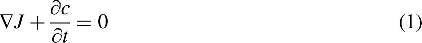
Stress migration is a diffusion-controlled mass transport process. The atomic diffusion is governed by the mass conservation equation:


When the samples are under heating condition, the Ag film is subjected to thermal stress because of the mismatch in thermal expansion coefficient between the metals of the multilayered structure. Preprocessed artificial holes in the samples generate local lower hydrostatic compressive stress sites in the Ag film. The Ag atoms migrate to the holes under the drive of the hydrostatic stress gradient and form Ag micro-particles. Finite element method was used to simulate the fabrication processes of Ag micro-particles. The commercial software ABAQUS was applied to conduct the numerical analysis. As ABAQUS has no analysis module related to metallic atoms migration, the mass diffusion analysis, which models the transient and steady-state diffusion of one material through another, was employed instead in this work based on the consideration that the governing equations of SM and mass diffusion are similar. Due to the periodicity of the sample structure, a representative volume element (RVE) shown in Figure 1 was selected for the simulations. The analysis was divided into two steps: the first step is thermal–mechanical simulation to analyze the hydrostatic stress distribution in the Ag film under heating conditions; the second step is mass diffusion simulation to investigate the atoms’ migration behavior using SM.
In step I simulation, a central symmetry finite element model of the RVE was applied to simplify, as shown in Figure 3. It was a multilayered structure consisted of Cu, Ti, Ag, and TiN. The length of the structure was 10 μm. The thickness of the Cu substrate was selected as 10 μm in the finite element model since it has been verified that a larger thickness of Cu substrate has little effect on the hydrostatic stress distribution in the Ag film. The mechanical properties of each material are listed in Table 1. In step I simulation, the initial temperature of the model was set to be 25 °C (room temperature) and a heating temperature of 300–600 °C was defined as the boundary condition. Due to the mismatch of the thermal coefficients of different materials, the hydrostatic stress distribution in the Ag film generated by steady-state thermal stresses can be obtained.

Finite element model of representative volume element (RVE) and local view around the hole of mesh for thermal–mechanical simulation.
Materials properties for thermal–mechanical simulation.

The step II simulation is atomic migration and the mass diffusion modules in ABAQUS were used instead. The mass diffusion behavior is described by an extended form of Fick's law expressed as follows:
23

For the step II simulation, only the Ag film was taken into account. A central symmetry finite element model consisted of the Ag film and a preset blank area for Ag atoms accumulation shown in Figure 4 was employed. The hydrostatic stress distribution of Ag film obtained in step I simulation was applied as boundary condition in the Ag film in this step analysis. The material parameters involved in SM of Ag in step II simulation are listed in Table 2. 24
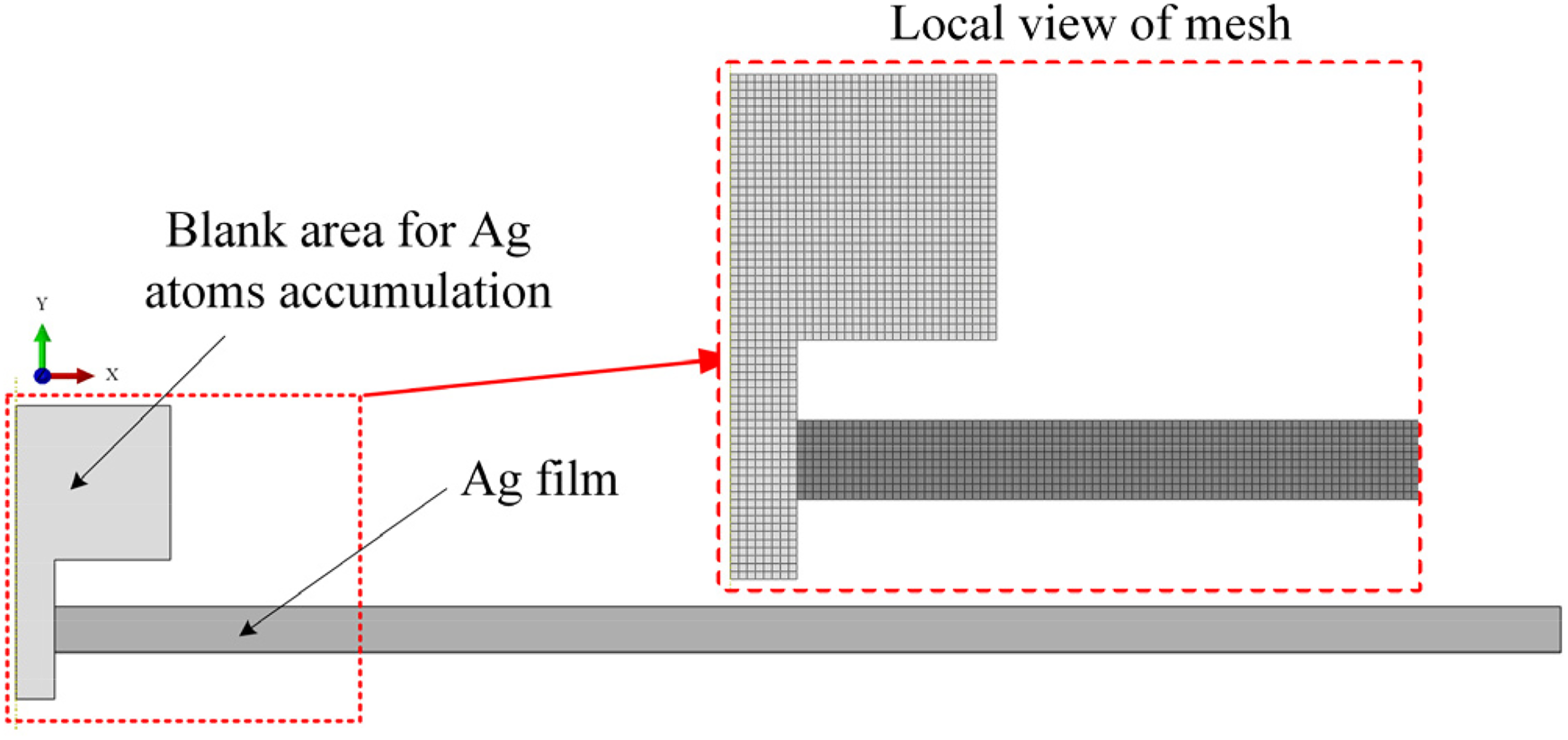
Finite element model for mass diffusion simulation in step II.
Materials parameters of Ag film for SM simulation. 24

Results and discussion
Hydrostatic stress distribution in Ag film
Figure 5 shows the step I simulation results of hydrostatic pressure distribution of the multilayered structure with the Ag film thickness of 300 nm and the TiN passivation layer thickness of 300 nm under the heating temperature of 500 °C. High hydrostatic pressure generated in the Ag film because of its much larger thermal expansion coefficient and the expansion was restrained by Ti and TiN layers. However, a negative pressure area was observed in the Ag film near the free surface because of the existence of the artificial hole, and large pressure gradient exists in this area. Figure 5(b) presents the variation of hydrostatic pressure and its gradient from the free surface to the inner part along the center path. It shows that significant hydrostatic pressure gradient exist in the range of about 0–0.5 μm distance to the free surface, which will drive the Ag atoms migration from high hydrostatic pressure area (inner part) to low hydrostatic pressure area (near the free surface) and the driving force of atom migration increases with the increase of hydrostatic pressure gradient.
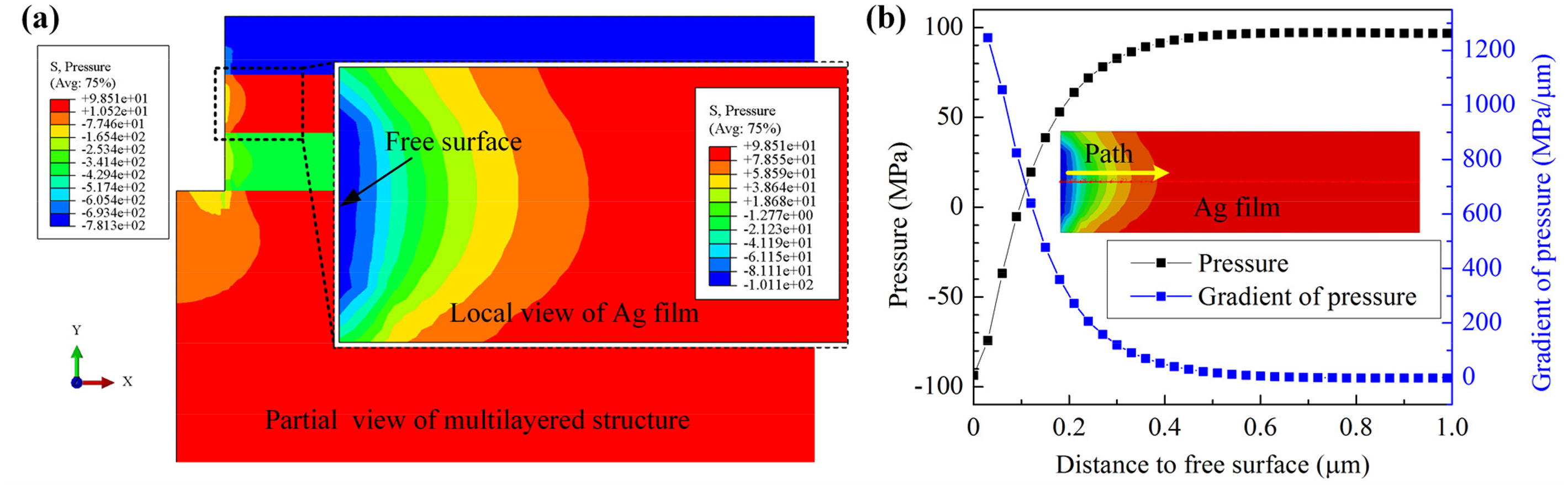
Results of step I simulation of (a) hydrostatic pressure distribution in Ag film and (b) variation of hydrostatic pressure and its gradient around the hole with the TiN thickness of 300 nm and heating temperature of 500 °C.
Previous studies have reported that the Ag film and passivation layer thickness of the multilayered structure sample and the heating temperature have much influence on the growth of Ag micro-particles. The passivation layer thickness used in previous research varied from 2 to 600 nm. 25 In this work, the influence of the passivation layer thickness on the hydrostatic stress distribution in the Ag film under heating conditions was investigated by numerical simulation.
Figure 6 presents the simulation result of hydrostatic pressure and its gradient distribution in Ag film with different passivation layer thickness in the multilayered structure sample. With the increase of TiN passivation layer thickness, the hydrostatic pressure in the Ag film decreases in the region nearby the free surface and increases in the inner part, as shown in Figure 6(a). The gradient of hydrostatic pressure curves presented in Figure 6(b) shows that the hydrostatic pressure gradient in the region nearby the free surface has a significant increase when the TiN passivation layer thickness increases from 2 to 150 nm and remains unchanged when the TiN thickness is larger than 150 nm. From the viewpoint of obtaining higher driving force of Ag atoms migration, it should be better to cover a TiN passivation layer with thickness more than 150 mm. At the same time, a higher hydrostatic pressure condition in the Ag film may also have effect on the Ag atom diffusivity according to equation (3). So, the TiN passivation layer with large thickness is not recommended from the standpoint of quick fabrication of Ag particle using SM.

Simulation results of hydrostatic pressure gradient around the microhole in Ag film with different TiN cover layer thicknesses with heating temperature 500 °C.
Heating temperature is one of the key factors that effect on the Ag atoms migration behavior in SM. On the one hand, higher temperature leads to a higher atomic diffusivity which makes Ag atoms migrate easily. On the other hand, it has much influence on the hydrostatic stress distribution in the Ag film. The simulation results of hydrostatic pressure and its gradient distribution under different heating temperature are provided in Figure 7. A higher heating temperature leads to a larger value of hydrostatic pressure in the inner part and a lower value around the free surface area of the Ag film, as shown in Figure 7(a); as a result, it exhibits a larger hydrostatic pressure gradient which is shown in Figure 7(b).

Simulation results of hydrostatic pressure gradient around the microhole in Ag film different heating temperatures of sample with 300 nm TiN passivation layer.
Atoms migration and the formation of Ag particle
The hydrostatic pressure distribution of the Ag film obtained in step I simulation with different TiN passivation thickness and the heating temperature were applied as boundary conditions to the Ag film in step II simulation. Figure 8 shows the mass diffusion transient analysis results of atomic concentration redistribution induced by the hydrostatic pressure gradient in the Ag film of which the TiN passivation thickness is 300 nm and the heating temperature is 500 °C. Firstly, from Figure 8(a) and (b), it can be seen that the Ag atoms migrate from the area nearby the artificial hole to the free surface under the driving of hydrostatic pressure gradient, because the inner area has higher hydrostatic pressure stress than the free surface area, which was illustrated in Figure 5. As a result, the area nearby the hole presented a low atomic concentration zone shown in Figure 8(b) and the minimum normalized concentration is ∼0.9377. Then, by comparing Figure 8 (c) with (b), it shows a slight increase of minimum atomic concentration in the area nearby the hole, which indicates that the Ag atoms of inner part of Ag film have migrated to this area due to the existence of a concentration gradient. Thus, as a result, the Ag atomic concentration redistributed and achieved a new equilibrium state under the driving of hydrostatic pressure gradient and concentration gradient and the maximum normalized atomic concentration is ∼1.313 near the free surface area as shown in Figure 8(d). So, the Ag atoms can overflow continuously from the free surface into the hole and accumulate to form the micro-particles. However, it should be noted that the redistribution process occurred in a very short time of just 10–100 ms according to the transient mass diffusion simulation result. Also, the simulation did not consider the discharge of Ag atoms from the free surface of the hole.

Redistribution of Ag atomic concentration due to hydrostatic pressure gradient in mass diffusion simulation: (a) initial state, (b) Ag atoms migrate from high pressure area to low pressure area, (c) Ag atoms migrate from high concentration area to low concentration area, and (d) final equilibrium state.
Since the finite element model cannot simulate the growth process of Ag micro-particle accurately and quantitatively with the increasing of time, we can apply the mass diffusion analysis module to analyze the redistribution of atomic concentration of Ag film by assuming that the blank area (illustrated in Figure 4) has the same material properties of Ag film but with initial atomic concentration of zero, and the Ag atoms in the Ag film can discharge from the free surface when its normalized concentration is >1.05. 26 At the same time, the Ag atoms are also subjected to resistance when they discharge from the artificial holes and form particles. The discharge resistance, on the one hand, comes from the channel resistance of the artificial hole and on the other hand, comes from the gravity of the discharged Ag atoms, which was illustrated in Figure 9. In the SM tests, the Ag particles continuously grow as the Ag atoms discharge from the Ag film. However, when the discharge resistance and internal atomic migration driving force caused by the stress gradient reach a balance, the growth of Ag particle will stop. That is to say, the size of the generated Ag particle was determined by a confluence of the internal stress gradient of the Ag film and the discharge resistance.

Schematic diagram of discharge resistance.
To analyze the increase trend of the atoms discharge resistance, an infinitesimal body was defined as shown in Figure 9. The resistance force of it was assumed to be expressed as the following:

Figure 10 shows the simulation results of the redistribution of the Ag atomic concentration and the formation of Ag particles. The Ag atoms discharge from the free surface first as shown in Figure 10(a), then accumulate and discharge from the hole as shown in Figure 10(b), grow to micro-particles on the hole position as shown in Figure 10(c), and the Ag particles finally stop to grow as the driving force and discharge resistance reach a balance as shown in Figure 10(d).

Process of Ag micro-particle formation: (a) stage I, Ag atoms discharge from the hole free surface; (b) stage II, Ag atoms discharge from the artificial hole; (c) stage III, Ag atoms accumulate and form micro-particle (d) stage IV, Ag micro-particle stop to grow while atoms migration driving force and discharge resistance reach a balance.
The normalized atomic concentration distribution along the Ag film at the middle position of thickness at the four stages are presented in Figure 11. It shows that the atomic concentration in the Ag film decrease in the area nearby the hole and the range of decreased concentration area expands continuously. Also, it can be drawn that the areas where the atomic concentration changes obviously were in the range of 0–7.5 μm to the hole surface when the Ag micro-particle with radius of 1 μm formed in stage IV as shown in Figure 10(d). That is to say, the distance between the artificial holes should not be <15 μm to avoid the interference of adjacent Ag micro-particles growth in the fabrication of Ag micro-particles array by experiments.

Distribution of atomic concentration in the Ag film at different stages of the formation of Ag micro-particle.
Figure 11 presents the variation curve of Ag particle size generated at the artificial hole of the samples with different passivation layer thicknesses and under different heating temperatures. The simulation results in Figure 12(a) and (b) both indicate that the size of Ag particles increases with the increase of heating time, and it will stop growing when the size reaches to a certain extent, which indicates the balance of atoms migration driving force and discharge resistance in the Ag film. Also, the final size of the Ag particle presented in Figure 12(a) shows that too thick and too thin passivation layers are both not conducive to the formation of larger particles. That is because a thinner passivation layer leads to a relative low atom migration driving force as illustrated in Figure 6 and thicker passivation layer resulted in higher resistance while atoms discharge from the artificial hole. And based on the simulation result, passivation layer with thickness in the range of 50–300 nm is acceptable and 150 nm is optimal. Figure 12(b) presents the Ag particle size growth under different temperatures with passivation layer thickness of 300 nm and the results indicate that higher heating temperatures will result in larger particle sizes and reach a balance condition more quickly. On the one hand, the higher the temperature, the greater the hydrostatic stress gradient and the larger the migration driving force, which can drive more Ag atoms to discharge from the artificial hole to form larger Ag particles. On the other hand, temperature has a very significant effect on the rate of atomic diffusion, and Ag atoms can migrate out of the silver film more quickly at a higher temperature. With the heating temperature of 300 °C, the generated atom migration driving force of hydrostatic stress gradient is less than the discharge resistance, and no atoms discharge from the artificial hole. Also, it should be noted that the influence of passivation layer thickness on the size of the generated particle is very limited comparing to heating time based on the simulation results shown in Figure 12. Thus, the controllable preparation of Ag particles can be realized by controlling the heating temperature.
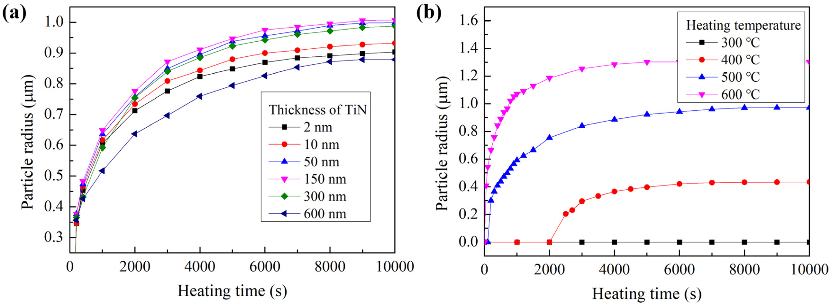
The variation curve of Ag particle size versus heating time (a) with different passivation layer thickness and the heating temperature is 500 °C and (b) under different heating temperature with passivation layer thickness is 300 nm.
To verify the simulation results, many experiments of the multilayered structure samples with different TiN passivation layer thickness and under different heating temperatures were conducted. Figure 12 shows the experimental result of the sample with TiN passivation layer thickness of 150 nm and the heating temperature of 500 °C for 3 h. Ag micro-particles were successfully produced; however, the break of passivation layer was observed in the sample surface as shown in Figure 13. It is possible that the extrusion stress at the artificial hole exceeded the fracture stress of local passivation layer material. Thus, a thicker TiN passivation layer can be applied to avoid this phenomenon.

The phenomenon of TiN passivation layer break.
Figure 14 shows the experimental results of the multilayered samples with 300 nm thick TiN passivation layer under the heating temperature of 500–600 °C for 3 h. It should be noted that too high heating temperature will lead to large stress in the multilayered structure due to the mismatch of the thermal expansion coefficient of different materials, which may exceed the materials fracture strength or bonding strength of the interfaces and lead to delamination cracks. The FE-SEM photo of the cross-sectional view of the samples showed that the multilayered structure retains integrity with a heating temperature of 500 °C as shown in Figure 14(a), while delamination cracks were observed in the sample when the heating temperature was 600 °C as shown in Figure 14(b). The cracks that occurred in the multilayered sample will release the hydrostatic stress in the Ag film and reduce the driving force of Ag atoms migration. That is to say, the heating temperature for the fabrication of Ag particles was not the higher the better.
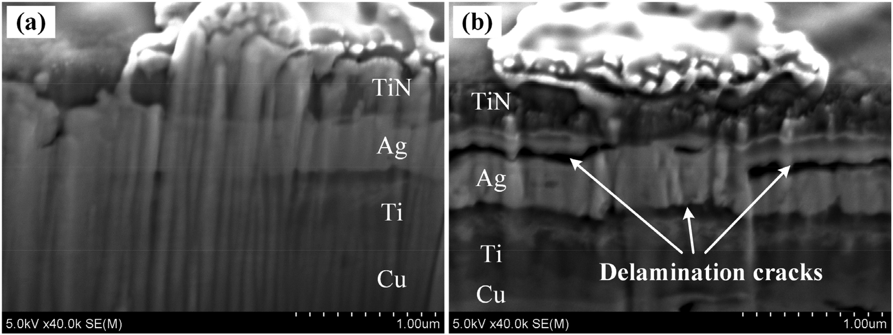
Cross-sectional view of experimental results of samples after heating for 3 h with heating temperature of (a) 500 °C and (b) 600 °C.
According to the simulation results mentioned above, the multilayered samples were prepared with a TiN passivation layer thickness of 300 nm and the artificial holes array were preprocessed with adjacent space of 15 μm. As the samples were placed in a furnace with heating temperature of 500 °C for 3 h, an array of Ag micro-particles with relative uniform size were successfully fabricated at the position of artificial holes as shown in Figure 15(a), and it can be seen in Figure 15(b) that the radius of the particle is about 1 μm. The cross-section of the formed Ag particle is shown in Figure 15(c). Also, the particles were detected using EDX, as shown in Figure 15(d), which verified that the micro-particle was composed of Ag. These experimental results indicated that the preparation method based on SM on multilayered samples for controllable and mass production of Ag micro-particles was practicable.

FE-SEM micrograph of experimental results: (a) formation of Ag micro-particle array on artificial hole positions, (b) image of a single Ag micro-particle, (c) cross-section of the Ag micro-particle, and (d) spectral analysis of the Ag micro-particle by EDX.
Conclusion
In this study, the method for the mass fabrication of Ag micro-particles at the predetermined positions based on SM on a multilayered structure sample was proposed. The multilayered structure consisted of a copper foil substrate, a 300 nm-thick Ti adhesive layer, a 300 nm-thick Ag film layer and a TiN passivation layer and an array of artificial holes were preprocessed on the sample surface. In high temperature, thermal stress was generated in Ag film because of the mismatch of thermal expansion coefficients of different layer materials. So, the Ag atoms can migrate and discharge from the artificial holes and form the Ag particles under the driving of hydrostatic pressure gradient and atomic concentration gradient in the Ag film. Finite element method was applied to analyze the distribution of hydrostatic pressure and its gradient in Ag film under heating conditions. The simulation results reveal that the pressure gradient increase with of thickness of TiN passivation when the thickness is <150 mm and it will remain unchanged when the TiN passivation is larger than 150 mm. Higher heating temperature can lead to more significant hydrostatic pressure gradient in the Ag film, but the experimental results with heating temperature of 600 °C indicated that excessive high temperature will lead to delamination cracks between different material layers, which will release the hydrostatic pressure in the Ag film. The growth of Ag particle on the predetermined position of artificial holes were also simulated by the finite element method. The Ag particles grow with the increase of heating time and the growth rate gradually slowed down. The particle size will remain unchanged while the atom migration driving force and the discharge resistance reach a balance. Higher heating temperatures can lead to larger Ag particle sizes and reach a balance condition more quickly, which indicates that the controllable preparation of Ag particles can be realized by controlling the heating temperature. In addition, the mass diffusion analysis on the redistribution of atomic concentration in the Ag film during the formation of Ag particles showed that the areas where the atomic concentration changes obviously were located in the range of 0–7.5 μm to the hole surface, which indicates that the space of adjacent artificial holes should not be <15 μm to avoid interference of nearby Ag particles growth. Thus, the TiN passivation layer thickness of 300 nm was applied and the adjacent space of the array of artificial holes was chosen as 15 μm in the multilayered sample and in the heating temperature of 500 °C for 3 h, an array of Ag micro-particles with radius of about 1 µm were successfully fabricated. The experimental results demonstrated that the proposed preparation method for controllable and mass production of Ag micro-particles was practicable.
Footnotes
Declaration of conflicting interests
The authors declared no potential conflicts of interest with respect to the research, authorship, and/or publication of this article.
Funding
The authors disclosed receipt of the following financial support for the research, authorship, and/or publication of this article: National Natural Science Foundation of China (No. 52005219, 51775242, 61704067) and Zhejiang Provincial Natural Science Foundation of China (No. LQ19E050008).