
Abstract
A lot of studies have shown that the hydraulic characteristics of orifice plate are mainly controlled by its contraction ratio, but the thickness of square-edged orifice plate also has many impacts on energy loss characteristics. The primary objective of this study was to investigated the effects of square-edged orifice plate thickness on energy loss characteristics. In this paper, the effects of square-edged orifice plate thickness on energy loss characteristics are investigated by numerical simulation using CFD. Orifice plate discharge tunnel is axial symmetric, two dimensional numerical simulations of orifice plate discharge tunnel flow was used. The equation (9) for calculating energy loss coefficient of square-edged orifice plate energy dissipater considering the influence of thickness is proposed. The results of the present research demonstrate that energy loss coefficient decreases with increase of the orifice plate thickness. The results of model experiment are consistence with the results calculated by using rectified equation in present paper. The CFD simulations and Model experiment for the flow through an orifice plate are carried out. For square-edged orifice plate energy dissipater, the relative orifice plate thickness T/D has remarkable impacts on its energy loss coefficient ξ. The Traditional equation (8) is corrected by numerical results. The equation (9) for calculating energy loss coefficient of square-edged orifice plate energy dissipater considering the influence of thickness is proposed and this equation is available in the condition of d/D = 0.4–0.8, T/D = 0.05–0.25, and Re > 105(Re is Reynolds number). Comparing with the physical model experimental data, the relative errors of equation (9) is smaller than 15%.
Introduction
Through years of hydropower projects development, the height of dams has exceeded the 300 m level, such as the dam which is 315 m high in Shuangjiangkou hydropower project in Sichuan province, China. 1 Flood discharge energy dissipation has an important impact on the safety of the dam. The orifice plate, as a kind of energy dissipaters with sudden reduction and sudden enlargement forms, has been widely applied in large-scale hydropower projects, due to its simple structure, high energy dissipation ratio, convenient construction and other known advantages. 2 In the 1960s, orifice plate has been successfully applied. A plug dissipater (which is similar to orifice plate), was successfully used in Mica dam flood discharge tunnel in Canada. 3 Energy dissipation ratio (the ratio between dissipation energy and total energy) can get to 50%. 4 In the Xiaolangdi Projects of China, three-stage orifice plate also was applied in 2000, and the energy dissipation ratio achieved 44%; the flow velocity through the gate was controlled effectively less than 35 m/s under the condition of the head of 145 m. 5 Therefore, orifice plate has an important function of dissipation of flow energy in high dam projects and its energy characteristics should be researched carefully.
Square-edged orifice plate discharge tunnel flow as a typical separated internal flow is typically unsteady and includes flow reversal, three-dimensional separation, and vortex formation and shedding. As shown in Figure 1, the flow energy is dissipated by the vortexes which formed due to its sudden reduction and sudden enlargement in upstream and downstream recirculation region of the orifice plate and shear and turbulence layers of the strong flow when it passes through the orifice. As a result, many studies have focused on the orifice plate energy loss coefficient. Wu and Ai 4 and Liu et al. 6 researches showed that the energy losses increased if the contraction ratio decreased. Singh et al. 7 performed the effect of plate thickness on the energy loss coefficient using computational fluid dynamics (CFD) under the nonstandard condition. Four different kinds of the ratio between orifice diameter and pipe diameter and Reynolds number (Re) were used. The results show that the ratio has proportional effects with respect to the orifice plate thickness for a higher ratio and has inversely effects with respect to the plate thickness for a lower value of ratio. Ai and Wang 8 studied minimum wall pressure coefficient of orifice plate energy dissipater through physical model experiments. In their results, the minimum wall pressure coefficient is mainly dominated by the contraction ratio and relative thickness. Parshad and Kumar 9 studied the effect of change in diameter of orifice on the flow characteristics. The results showed small increase in value of coefficient of discharge with increase in diameter of orifice. Shan et al. 10 presented the effects of the orifice to pipe diameter ratio on the flow field behind a thin circular square-edged orifice plate by adopting a planar particle image velocimetry (PIV) system. The results show that the local peak Reynolds stresses have been found to be independent of beat ratio in the shear-layer region close to the orifice plate. Benhamadouche et al. 11 predicted the accuracy of the velocity, the Reynolds stresses, the pressure loss and the discharge coefficient for a flow through a square-edged orifice in a round pipe at a Reynolds number of 25,000 using a wall-resolved Large Eddy Simulation (LES). The LES results showed good agreement with the velocity from the experimental data. The profiles of the Reynolds stresses were similar, but an offset was observed in the diagonal stresses. Abd et al. 12 experimental studied effect of diameter of orifice which has a sharp-edged with 30° angle and Reynolds number on the discharge coefficient values. They concluded that orifice diameter has a positive effect while Reynolds number inversely affects the value of discharge coefficient. Ahmed and Ghanem 13 investigated viscous, incompressible flow through square-edged concentric orifice plate and the performance of discharge coefficient consequent to variations of Reynolds number, orifice/pipe diameter ratio, and orifice thickness ratio, through a two-dimensional axisymmetric numerical model. They proposed correlation for discharge coefficient.

Flow through orifice plate.
A thoroughly literature review reveals that the researches only focused on the discharge coefficient and the energy dissipation ratio with a wide range of orifice diameter. As a matter of fact, the square-edged orifice plate thickness (T) effects its backflow region length (Lb), and the backflow region is one of the important sources of orifice plate’s energy loss, the effect of square-edged orifice plate thickness (T) on its energy loss coefficient is also remarkable. Thus it is necessary to research the effect of orifice plate thickness (T) on its energy loss coefficient. In the present study, the effect of the square-edged orifice plate thickness on energy loss coefficient is investigated under different diameters of square-edged orifice plate (d) and the diameters of flood discharge tunnel (D). The flow through the square-edged orifice plate discharge tunnel is simulated and analyzed by numerical simulations and model experiments. The d/D is set in range of 0.4–0.8, and T/D is set in range of 0.05–0.25. The empirical calculation equation for energy loss coefficient of orifice plate is corrected by simulation and model experiments.
Numerical methods
Governing equations and boundary conditions
The commercially available CFD code FLUENT has been used in the present study. In order to simulate the flow through an orifice plate, the governing equations with the appropriate Reynolds stress closure need to be solved. The RNG k–ε model due to good suitability, high precision and calculation stability, has been used to calculate orifice plate flow parameters.14,15 The governing equations of RNG k–ε model include continuity, momentum and the k–ε closure equations. 16 Since the problem is assumed to be steady and incompressible turbulent flow, the governing equations are given as:


The governing equations RNG k–ε model are as follows,


where, Gk is the generation of turbulent kinetic energy due to the mean velocity gradient, and is calculated as:

The velocity inflow boundary model of FLUENT is chosen, in which three inflow conditions are considered: average velocity of flow in the inlet, the turbulent kinetic energy kin and the turbulent dissipation rate εin. In velocity inflow boundary model, if the above three inflow boundary conditions are set, the pressure boundary is already included in them, so it is not necessary to set pressure inlet separately. The turbulent kinetic energy kin and the turbulent dissipation rate εin in the inflow boundary are expressed:

where, uin is average velocity in the inlet. In the outflow boundary, the flow can be deemed as developed fully (flow developed fully means flow’s pressure do not vary along its travel). The method of wall functions was used near wall. In mesh generation of wall functions, it is not necessary to encrypt the mesh on the wall, but only to place the first inner node in the region where the turbulence is fully developed. And the flow’s radial velocity on symmetry axis is considered as zero.
Mesh
A grid independence study was performed to find the mesh size that was sufficiently fine so that solution does not change by further refining the mesh, as shown in Figure 2. In order to fully develop the flow, the starting section is selected at 6D before the orifice plate (D is the diameter of the orifice plate discharge tunnel), and the ending section is selected at 8D after the orifice plate. The purpose of this is to ensure convergence at high flow rate. As the orifice plate discharge tunnel is strictly axisymmetric, only the area above the axial section of the orifice plate discharge tunnel is selected for calculation. The specific division method is as follows: on the longitudinal and transverse boundaries, the diameter and length range of each orifice plate discharge tunnel is taken as 100 nodes. Therefore, the total number of grids in the whole calculation area is 70,000 + 5000αη (α is thickness diameter ratio and η is aperture ratio).

Typical mesh for orifice plate discharge tunnel.
Solution scheme
A 2D axi-symmetry flow simulations are carried out. The finite volume method and a staggered grid are employed. The basic equations are integrated over each control volume to obtain discretization equations. The pressure implicit in the splitting of operator (PISO) algorithm is used to solve the velocity and pressure fields. The block-off method is adopted to treat the control volumes occupied by the plug so that the variables in these control volumes remain equal to 0 throughout the whole computation process. 17
Numerical simulation methods
Because orifice plate discharge tunnel is axial symmetric, two dimensional numerical simulations of orifice plate discharge tunnel flow can be used. The energy loss coefficient can be calculated by using the following:18–20

where p1 is the pressure in flow undisturbed section before orifice plate, p2 is the pressure in flow already recovery section after orifice plate, ρ is flow’s density, u is flow average velocity in discharge tunnel. Because when Reynolds number is more than 105, Reynolds number has little effects on energy loss coefficient and its effects can be ignored.21,22 Reynolds numbers arranged in simulation are all larger than 105 and their effects are all ignored in this paper’s simulation.
Results
Simulation results
The results of simulation are shown in Table 1. ξs is simulation energy loss coefficient in Table 1. It can be seen from Table 1 that the effect of orifice plate thickness is significant, and energy loss coefficient decreases with increase of the orifice plate thickness. Traditional equation (8) can be corrected by regression analysis data in Table 1 to equation (9):

can be corrected by regression analysis data in Table 1:

The results of simulation.

This equation (9) is available in the condition of d/D = 0.4–0.8, T/D = 0.05–0.25, and Re > 105(Re is Reynolds number).
Model experiment verification
The experimental physical model is shown in Figure 3, which includes one intake system, one tank, one discharge tunnel, and one return system with rectangular weir and some orifice plates. The tunnel model diameter (D) is 0.21 m, and the tunnel model length is 4.75 m from the intake to the outlet at the gate. The 10.0D water head could be achieved by the intake system and the tank. About 35 pieces of small plastic tube along tunnel wall were utilized to measure wall pressure. The wall pressure of orifice plate is measured by theses manometer tubes. It was proved to be reasonable that the positions of the measured pressure points were placed at 0.5D from the upstream face of the orifice plate and at 3.0D from the downstream face of the orifice plate by the pre-experiments. The flow weir is used to measure the flow, and then the average flow velocity of the spillway tunnel can be obtained by dividing the spillway tunnel sectional area.
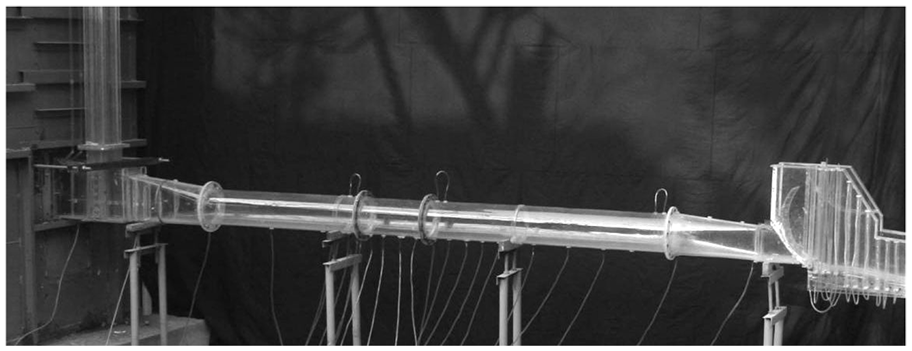
Discharge tunnel model.
The results of experiment are shown in Table 2. The meanings of each symbol in Table 2 are as the following: p1 (Pa) is the wall pressure before 0.5D orifice plate, p2 is the wall pressure after 3D orifice plate; Re is Reynolds number of flow through discharge tunnel; H (m) is the height of tank water (water level). Q (m3/s) is discharge volume, ξe is experiment energy loss coefficient.
The results of experiment.

Discussion
The comparisons between experiment and simulation are shown in Table 3. In Table 3, ξe is experiment energy loss coefficient and ξs is simulation energy loss coefficient. The error is calculated by the following equation:

Comparisons between experiment and simulation.

Table 3 shows that the simulation results are very close to the physical model experiment results, and the maximum deviation is not more than 6.5%
The comparisons between calculation results by using traditional empirical equation (8) and calculation results by using equation (9) are shown in Table 4. The meanings of symbols in Table 4 are as the following: ξ1 is the calculation energy loss coefficient by using traditional empirical equation (8); ξ2 is the calculation energy loss coefficient by using equation (9). Er1−m is relative error of comparisons between calculation results by using traditional energy loss coefficient empirical equation and experiment results. Er2−m is relative error of comparisons between calculation results by equation (9) and experiment results. Er1−m and Er2−m can be expressed by equations (11) and (12) respectively.


The results of comparison.

The data in Table 4 illuminate that the maximum relative error between experiment data and equation calculation result by using traditional empirical equation (8) can reach to 33%, and the maximum relative error between experiment result and calculation result by using equation (9) can reach to 15%. The effect of orifice plate thickness is remarkable and cannot be ignored. The calculation results by using equation (9) are close to actual results, so equation (9) can be used to calculate energy loss coefficient of square-edged orifice plate instead of traditional empirical equation.
Conclusions
The CFD simulations and Model experiment for the flow through an orifice plate are carried out. For square-edged orifice plate energy dissipater, the relative orifice plate thickness T/D has remarkable impacts on its energy loss coefficient ξ. The Traditional equation (8) is corrected by numerical results and model tests. The equation (9) for calculating energy loss coefficient of square-edged orifice plate energy dissipater considering the influence of thickness is proposed and this equation is available in the condition of d/D = 0.4–0.8, T/D = 0.05–0.25, and Re > 105(Re is Reynolds number). Comparing with the physical model experimental data, the relative errors of equation (9) is smaller than 15%.
Footnotes
Appendix
Declaration of conflicting interests
The author(s) declared no potential conflicts of interest with respect to the research, authorship, and/or publication of this article.
Funding
The author(s) disclosed receipt of the following financial support for the research, authorship, and/or publication of this article: Supported by the CRSRI Open Research Program (Program SN: CKWV2019729/KY) and ningxia colleges and universities scientific research projects (NGY2018241)