
Abstract
To improve load capacity and transmission characteristics of crossed-axis helical gear drive, a generation approach of the gear pair with small-angle based on the curve contact element is proposed. Contact principle based on spatial curve meshing relationships is introduced and geometric models of tooth profiles are developed according to a pair of mated conjugate curves. Furthermore, a mathematical model of crossed-axis helical gear drive with small-angle is established. Numerical examples are illustrated for this research using the 10° shaft angle, and the computerized simulation is also developed based on the solid models. According to gear geometry and finite element method, general characteristics including undercutting conditions, sliding ratios and contact stress for tooth profiles are analyzed. Comparisons with crossed-axis involute gears are also carried out. Finally, the gear prototype is processed using the gear milling method and a basic performance test is conducted. Analysis results show that the new gear pair has well contact characteristics. Further studies on the dynamic analysis and precision manufacturing method will be carried out.
Keywords
Introduction
More researchers have paid the attentions to the crossed-axis helical gears for current research involving the fields of automobile differential mechanism, helicopter speed reducer, robot constructions and conveyor driving systems, etc. Usually, tooth profiles of the crossed-axis helical gears mesh with point contact and have the large tooth flank gap. 1 Series of works detailing their basic design principle, analysis, manufacturing and inspection had been developed and utilized to fulfill different application requirements. Litvin et al. 2 proposed generation process and design approach of standard and non-standard involute crossed helical gears, respectively, using the two generating rack-cutters with a common normal section. Antal and Antal 3 present the addendum modification method for design of crossed axes helical gears according to the engagement sliding conditions. Takahashi et al. 4 performed endurance experiments for plastic crossed helical gears with grease lubrication. The failure mode of plastic crossed helical gears under grease lubrication conditions is tooth breakage. Additionally, an index for lifetime evaluation was also provided. Hsu and Su 5 utilized the modified variable tooth thickness hob to reduce the tooth flank twisting of a longitudinal crowning gear under the conditions of unchanged center distance. Considering the modification of teeth, misalignment error, and machining error, Wang et al. 6 put forward an approach for computerized simulation of double helical gears with crossed-axis. Meshing model and TCA procedure of the gears were given. Liu et al. 7 investigated the influence of work holding equipment errors on meshing behavior and gear flank geometry of face-hobbed hypoid gear based on accurate mesh model which established from generated process. Song et al. 8 analyzed the dynamic characteristics of a marine gearbox with crossed beveloid gears by finite element method.
Crossed-axis helical gears are not widely used for high power motion due to their lower load capacity because of load concentration and varied contact ratio. The authors proposed a new design theory for gear transmission based on curve contact element. A general principle, meshing characteristics analysis and manufacturing method of the gears with parallel axes or intersecting axes had been studied.9–16 Generation method and mathematical model of gear pair have been developed in terms of curve element. Related research conclusions can provide the theoretical basic and technical support for a new crossed-axis helical gear drive. To improve the load capacity and transmission characteristics of the crossed-axis helical gear drive, an approach for generation of the gear pair based on curve contact element is put forward. Mathematical model of the crossed-axis helical gear drive with small angle are established. General characteristics analysis of the new gear pair are also discussed.
Mathematical model of crossed-axis helical gear with small angle
The fixed coordinate systems S(O–x, y, z), Sp(Op–xp, yp, zp) and movable coordinate systems S1(O1–x1, y1, z1), S2(O2–x2, y2, z2) are established in Figure 1. The variables


Spatial coordinate systems of gear pair.
Supposed that the spatial curve
where t is curve parameter,
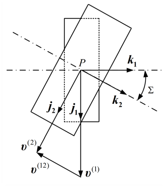
Spatial relationships between the gear pair.
The curve trihedron displayed in Figure 3 shows that the normal vector at contact point M can be represented by

Curve trihedron.
Furthermore, the meshing equation for the designated contact position can be calculated as

So the spatial curve

Through the provided equidistant-enveloping method,
10
action surfaces of tooth profiles are studied by the developed conjugate curves pair and the generation process is displayed in Figure 4. The respective equidistant curve

Generation of action surfaces.
So the general equations of tooth profiles are derived as

where
Specially, we developed the tooth profiles with convex-to-concave form according to the gear top and root surfaces. Meshing model of tooth profiles is displayed in Figure 5.

Generated tooth profiles with point contact.
Numerical example of gear pair with 10° angle
A cylindrical helix curve is located on pinion 1 and it is described as

where R is the pitch circle radius, θ is space curve parameter and p is helix parameter.
Substituting equation (6) to equations (3) and (4), the conjugated curve equation can be obtained as
Also the tooth profiles can be solved utilizing the developed equations as

and

Based on the design parameters in Table 1, we can calculate the data points results by MATLAB software. The schemes of cylindrical helix conjugate curves and tooth surfaces with 10° angle are shown in Figure 6.
Basic parameters of crossed-axis helical gear pair with 10° angle.


Simplified engagement model: (a) spatial curve pair and (b) mated tooth surfaces.
Furthermore, the solved data results of tooth profiles to the Pro/E software and the three-dimensional solid models of crossed-axis helical gear pair with 10° angle are established according to Boolean operations. The drawing images are shown in Figure 7.

3D solid models of crossed-axis helical gear pair with 10° angle: (a) convex pinion, (b) concave gear, and (c) assembly model.
Computerized simulation for engagement motion of tooth profiles is carried out. The meshing process of gear pair is shown in Figure 8. The results show that gear pair rotates with a fixed transmission ratio and continuous motion. For the axial direction, tooth profiles mesh in point contact and there is no engagement interference during the mated gear pair.

Computerized simulation of meshing process: (a) no engagement, (b) beginning engagement, (c) some engagement position, and (d) middle engagement position.
Characteristics analysis of the established tooth profiles
Undercutting conditions
The undercutting of tooth profiles usually occurs due to the appearance of a singular point. For the proposed crossed-axis helical gear pair with small angle, the pinion is easy to happen undercutting because of the few numbers of teeth. We discuss the undercutting conditions and supposed that the contact region equation is shown as

where ρa is convex tooth profile radius, ea and la is the movement and offset distances of circle center, respectively.
Considering that surface Σ1 is tool action surface and it is expressed in double-parameter form, tooth surface Σ2 is generated using the proposed surface Σ1. Singular points on surface Σ2 mean that this surface may happen to undercut during the generation process. Its mathematical descriptions is expressed by equation

where s is arc length parameter,

where
There is two unknowns

has two rank. And further it can be written as
where

Substituting equation (10) into above equations, the undercutting conditions of tubular tooth surfaces are obtained as


and
where

Considering the singularity condition of formed tooth profiles, and avoiding undercutting of generated tooth profiles, the equations are given as

The equations determine a line which has to limit the generating surface ∑1. In many cases, the undercutting can be avoided by choosing appropriate settings for surface ∑1 that generates ∑2.
Sliding ratios
The sliding ratios calculation of tooth profiles based on curve element is studied by Liang et al. 18 Similarly, supposing a driving gear with original curve Γ1 transmits movement to a driven gear with its conjugated curve Γ2, they contact at point K as displayed in Figure 9.

Sliding condition of tooth profiles.
ΔS1 and ΔS2 denote respectively the traveling arcs of conjugate curves Γ1 and Γ2 in a period of time Δt which approaches to zero during the meshing process. Assuming the relative sliding exists, the length of arc MM1 is not equal to that of arc MM2, and the difference between ΔS1 and ΔS2 is called the sliding arc. The sliding coefficient is analyzed as a ratio of the length of sliding arc relative to length of the corresponding arc in meshing area. So calculation formulas of sliding ratios of the crossed-axis helical gear pair with small shaft angle are expressed as

and

According to the given design parameters in Table 1, sliding ratios of the new gear pair are calculated and the result is shown in Figure 10(a).
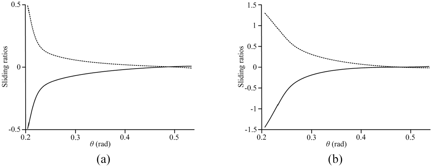
Sliding ratios calculation: (a) the new gear pair and (b) the involute gear pair.
The sliding ratios during the engagement process are the function with respect to parameter θ and the calculation values are variable related to the change of parameter θ. Sliding ratios of gear pair only pass through zero at pitch point and their symbols change due to the various direction of sliding velocity when the nearby contact points on both sides begin to mesh. The maximum absolute values occur at the tooth root where the gear teeth mesh in and out. However, because of the contact of convex and concave tooth profiles, the absolute values of sliding ratios are smaller than 0.5 with the growth of parameter θ. The sliding ratios of the corresponding crossed-axis involute gear drive are also calculated and listed in Figure 10(b) for comparison. Obviously, the sliding ratios of the new gear pair are smaller than that of crossed-axis involute gear drive, which can help to improve the transmission performance. The meshing process can realize limit position and the approximate pure rolling contact may be accomplished in theory.
Stress analyses
Stress analysis of tooth profiles can show the mechanics properties of the new gear drive. Finite element model of conjugate gear pair with 10° shaft angle is shown in Figure 11 and the model is analyzed with ANSYS Workbench. Considering the actual engagement conditions, gear pair is plotted with hexahedron unit Solid 185. Tooth profiles of the pinion and gear are defined as the contact surface and target surface, respectively, which are also corresponding to contact unit CONTA 173 and TARGE 170. Hertz model is applied to analysis process of contact stress. The extended Lagrange algorithm is regarded as the calculation method and MPC 184 constraint unit is also conducted to the whole process. The selected material for the simulation was 20CrMnTi steel, with Poisson coefficient of 0.25 and Young modulus of 205 GPa. A torque value of 200 Nm is applied to the pinion.

Finite element model of the new gear pair with 10° shaft angle.
Analysis results of the proposed new gear pair are displayed in Figure 12. The maximum contact stress is 1266.5 MPa. The maximum stress occurs at contact point, which locates on the middle of tooth profile. It has regular elliptical distribution along the direction of tooth width, and the distribution area has the trend of expanding to the tooth root direction. With the increase of the contact area, the contact stress will gradually decrease. The maximum von Mises stress of the pinion is 793.69 MPa.
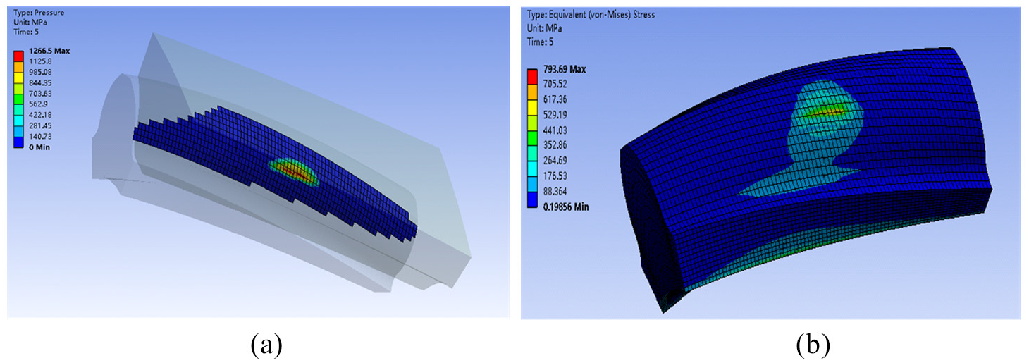
Stress analysis results of the new gear pair: (a) contact stress and (b) Von Mises stress of the pinion.
Under the same settings, the involute gear pair is used as the contrast object, and its contact state and finite element analysis results are shown in Figure 13. The maximum contact stress is 1639 MPa, which occurs at the meshing position, and the stress is distributed along the contact line. The maximum von Mises stress of the pinion is 1233.8 MPa. Obviously, contact stress results of the new gear pair are smaller than that of crossed-axis involute gear drive, which show the well contact capacity and strength.

Stress analysis results of the involute gear pair: (a) contact stress and (b) Von Mises stress of the pinion.
Gear prototype and experimental study
Gear milling method is used to achieve the gear pair due to the special tooth profiles form. According to an established solid model, the simulation motion process of machine tool with ball milling cutter can be obtained. The program of machining codes considering milling cutter and workbench motions is developed by CNC (Computer Numerical Control) five-axis machining center DMU60 in Figure 14(a). Generally, based on fast moving and feeding function of ball milling cutter, rotation function of working axis and workbench, the gear pair can be manufactured. The final generated pinion and gear are depicted in Figure 14(b) and (c), respectively.
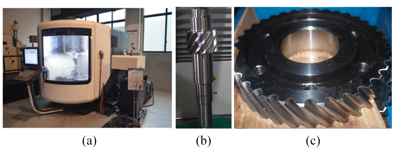
Gear prototype: (a) five-axis machining center DMU60, (b) the pinion, and (c) the gear.
Furthermore, performance experiment of gear prototype is carried out and the trial site is shown in Figure 15. The equipments are linked by spring coupling. Input and output torques are measured by torque and rotational speed transducer. Oil temperature in the box is measured by the temperature transducer. Rotational speed is controlled by the variable speed electric motor, and the gear pair is loaded by the loading motor.
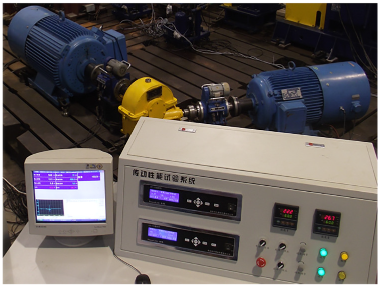
Gear prototype test.
The contact point between the conjugate tooth profiles will spread over a small area under the load due to elastic deformations. To achieve a better performance, it is necessary to carry out the running-in process. It can expand the contact area for increasing the load capability and modify the gear tooth surfaces for reducing noise and vibration. During the test process, transmission efficiency of gear prototype can be obtained and displayed in the screen through the backstage calculation formula
Transmission efficiency and oil temperature results under given work conditions are shown in Figures 16 and 17. It can be concluded that the transmission efficiency will increase by increasing rotational speed and keeping torque constant. Similarly, it will also increase by increasing torque and keeping rotational speed constant. The maximum efficiency may be up to 95.9% at the load of 600 Nm and the whole efficiency of gear prototype is in the range of 91.2%–95.9%. The oil temperature arrives at balance when the time is 70–80 min and the highest value of oil temperature is about 69.7°C with respect to the room temperature.

Transmission efficiency results of the new gear pair.

Oil temperature results of the new gear pair.
Conclusion
Contact principle and generation method of the gear pair with small angle based on curve contact element is proposed. The mated tooth profiles are developed through the given spatial conjugate curves. Mathematical model of the presented gear drive is established. Numerical example is illustrated using the 10° shaft angle, and the three-dimensional solid models of crossed-axis helical gear pair with 10° angle are established by MATLAB and Pro/E software. Computerized meshing motion is simulated and developed to verify the transmission conditions.
Considering the singularity condition of formed tooth profiles, and avoiding undercutting of generated tooth profiles, the general equations are derived. In additional, calculation method of sliding ratios of tooth profiles is provided based on the developed conjugate curves. Under the given parameters, sliding ratios of the new gear pair are calculated. The results are smaller than that of crossed-axis involute gear drive, which can help to improve the transmission performance.
Stress analysis of the new gear drive is carried out by ANSYS software. The maximum contact stress is 1266.5 MPa, occurring at contact point position, which locates on the middle of tooth profile. It has regular elliptical distribution along the direction of tooth width, and the distribution area has the trend of expanding to the tooth root direction. With the increase of the contact area, the contact stress will gradually decrease. The maximum von Mises stress of the pinion is 793.69 MPa. The involute gear pair is used as the contrast object, and the maximum contact stress is 1639 MPa, which occurs at the meshing position, and the stress is distributed along the contact line. The maximum von Mises stress of the pinion is 1233.8 MPa. Obviously, contact stress results of the new gear pair are smaller than that of crossed-axis involute gear drive, which show the well contact capacity and strength.
Gear milling method is used to achieve the gear pair due to the special tooth profiles form. According to performance experiment of gear prototype, the transmission efficiency will increase by increasing rotational speed and keeping torque constant. The maximum efficiency may be up to 95.9% at the load of 600 Nm and the whole efficiency of gear prototype is in the range of 91.2%–95.9%. The oil temperature arrives at balance when the time is 70–80 min and the highest value of oil temperature is about 69.7°C with respect to the room temperature.
The further study on the dynamic analysis and precision manufacturing technology will be carried out.
Footnotes
Declaration of conflicting interests
The author(s) declared no potential conflicts of interest with respect to the research, authorship, and/or publication of this article.
Funding
The author(s) disclosed receipt of the following financial support for the research, authorship, and/or publication of this article: This research was supported by National Natural Science Foundation of China (Grant No. 51975078), Fundamental Research and Frontier Exploration Program of Chongqing City (Grant No. cstc2018jcyjAX0029), Science and Technology Research Program of Chongqing Municipal Education Commission (Grant No. KJQN201900736) and Chongqing Key Laboratory of Urban Rail Transit System Integration and Control Open Fund (Grant No. CKLURTSIC-KFKT-202005).