
Abstract
This paper proposes a new research method in view of the rare research on the contact state of hybrid drive multi-degree-of-freedom motor. Firstly, the basic principle and structure of hybrid drive motor are introduced. The air gap magnetic field model and electromagnetic torque model of permanent magnet rotor are obtained by analytical method. Static analysis of piezoelectric stators are carried out by stress-strain relationship. According to the analytical method and the spatial geometric relationship, the piezoelectric driving torque under different driving conditions is obtained. Introducing Hertz contact theory and Mindlin theory, combined with piezoelectric driving torque, electromagnetic driving torque and load torque to analyze the friction situation. A friction interface model considering the dynamic nonlinearity of friction coefficient and the nonlinear change of friction force distribution is established. Finally, using Matlab software, the friction distribution diagram of the contact surface of the hybrid drive three-degree-of-freedom motor under different driving and motion states is obtained. The analysis results verify the rationality of the electromagnetic piezoelectric hybrid driven three-degree-of-freedom motor. It shows that the contact state of the three sets of piezoelectric stators are determined according to the driving condition and load, the relative speed of the piezoelectric stators and the spherical rotor is proportional to the frictional force. It provides an idea for the research of contact state of hybrid drive multi-degree-of-freedom motor, and also lays a basis for further optimizing the friction interface of this kind of motors or actuators.
Introduction
With the development of modern industrial technology, the mechanical system tends to be complicated, and the requirements for the accuracy of multi-degree-of-freedom drive devices are constantly increasing. Traditionally, the method for realizing multi-degree-of-freedom motion by multiple single-degree-of-freedom motors has many shortcomings, such as complex mechanical structure, large volume, low positioning accuracy, and low efficiency. 1 The multi-degree-of-freedom spherical motor has high integration, simple structure and can be used for precise motion control. Currently, there are two effective multi-degree-of-freedom driving methods: electromagnetic drive and piezoelectric drive.
The electromagnetic drive motor is suitable for low torque and high speed work, but its structure is complicated, the miniaturization is difficult, the control and positioning accuracy is low, and it is not suitable for precise work.2–6 Compared with traditional electromagnetic motors, piezoelectric drive motors have many advantages, such as: low speed and large torque, no electromagnetic interference, fast response, simple structure, self-locking of power failure, etc.,7–11 it is widely used in micro machines, medical equipment, precision machining and aerospace.12–16 But it is affected by friction materials, temperature, etc., and its life is short, which is not suitable for continuous work. 17 Therefore, combined piezoelectric drive and electromagnetic drive can not only avoid the shortcomings of the two drive modes, but also improve the output performance of the motor. 18 The mechanical characteristics of the hybrid drive motor are affected by the contact state of the piezoelectric stator and the rotor. So, establish the contact model between the piezoelectric stator and the rotor correctly is important, and provide a basis for further optimizing the friction interface. 19 At present, many scholars have done a lot of research on the stator-rotor friction model. Zhu 20 proposed a contact model based on elastic mechanics and friction layer deformation. Duan et al. 21 proposed a finite element frame for the piezoelectric coupling stator, the rotor and the contact interface, and analyzed the finite element method for the general intermittent contact problem of the piezoelectric drive. Fengyan et al. 22 proposed a contact model in which the stator friction layer is viscoelastic, and compared the model with a model in which the slider is flexible and the stator is rigid. The results show that the motor based on the model will get bigger. Stall torque and greater wear resistance. Jiang et al. 23 proposed a contact model in which the friction layer is rigid on the stator and the rotor is rigid. Yang et al. 24 proposed a hybrid excitation sandwich multi-degree-of-freedom ultrasonic motor. Four pieces of lead zirconate titanate ceramics are used in the motor, and three resonance modes are combined in pairs to drive the spherical rotor for multi-degree-of-freedom rotation. Shi et al. 25 Proposed an ultrasonic motor with ring stator structure. The motor combines the axial bending mode and the in-plane non axisymmetric mode to generate three kinds of ellipses at the four driving feet and realize the multi-degree-of-freedom motion. Huang et al. 26 Proposed a novel in-plane non axisymmetric spherical stator multi-degree-of-freedom ultrasonic motor. The stator and rotor of the motor adopt a piezoelectric ceramic spherical shell and two metal hemispherical shells respectively, which is conducive to the realization of high symmetry and miniaturization of the whole motor. But, few people have in-depth analysis of the contact state of hybrid drive multi-degree-of-freedom motors.
In order to deeply study the electromagnetic piezoelectric hybrid drive three-degree-of-freedom motor, the motor was modeled and analyzed. Firstly, the basic principle and structure of the hybrid drive three-degree-of-freedom motor are introduced. The electromagnetic-driven air-gap magnetic field model is established, and the electromagnetic drive torque is derived by analytical method. The static-mechanical analysis of the piezoelectric driven stator-rotor is obtained by stress-strain relationship to obtain the output torque generated by piezoelectric stators, and then the piezoelectric driving torque is vector analyzed by spatial geometric relationship. The Hertz contact theory and the Mindlin theory are combined with the superimposed electromagnetic torque and piezoelectric torque to analyze the frictional force distribution of the contact layer. The distribution of the piezoelectric stator torque and load torque under different driving conditions is considered, and the friction interface model considering nonlinearity is established. According to the experiment, the frictional distribution of the contact surface of the hybrid drive three-degree-of-freedom motor under different driving and motion states is obtained.
Electromagnetic piezoelectric hybrid drive three-degree-of-freedom motor structure and principle
Electromagnetic piezoelectric hybrid drive three-degree-of-freedom motor is composed of electromagnetic structure and piezoelectric structure as shown in Figure 1, (a) is the electromagnetic drive structure, (b) is the piezoelectric drive structure. The electromagnetic stator S4 has 18 slots, which are located outside the spherical rotor and fixed by a fixed device with a certain gap with the rotor; four permanent magnets with the same volume and shape but opposite polarization are installed on the outer surface of the spherical rotor and fixed on the outer surface of the rotor by pasting. The interaction between permanent magnet and electromagnetic stator S4 generates electromagnetic torque to drive the rotor to rotate.

Electromagnetic piezoelectric hybrid drive three-degree-of-freedom motor structure: (a) electromagnetic drive structure and (b) piezoelectric drive structure.
In the piezoelectric structure, three stators (S1, S2, S3) with the same structure are symmetrically distributed and fixed on the base body. Each stator is composed of elastic metal body and piezoelectric ceramic patch, and the piezoelectric ceramic material is PTZ-8 which can carry high power and realize high frequency motion, and the epoxy resin adhesive is pasted on the back of the elastic metal. The piezoelectric ceramic sheet polarizes in the thickness direction, and the two adjacent piezoelectric ceramic sheets polarize in the opposite direction, and finally form two spatially symmetric phases. When an alternating voltage with the same two-phase frequency, the same amplitude and a phase difference of 90° is applied to the piezoelectric ceramic, the micro-vibration generated on the piezoelectric stator is converted into frictional motion due to the inverse piezoelectric effect of the piezoelectric ceramic and resonance effect to drive the rotor to rotate. Since the axial directions of the three piezoelectric stators are not coplanar in space, a spatial three-dimensional torque direction can be generated, so the piezoelectric drive can cause the motor to achieve three-degree-of-freedom motion. The inner surface of the spherical rotor is coated with friction material to increase the friction contact with the piezoelectric stator.
Because electromagnetic drive can realize rotation motion, piezoelectric drive can realize three-degree-of-freedom motion of rotation and deflection, through coordinated control of the four stators and two drive modes, the motor achieves better three-degree-of-freedom motion.
Electromagnetic drive model
Magnetic field distribution
Since the internal energy conversion process of the motor is performed between the stator-rotor air gap, the magnetic field at the air gap is the main research object. The analytic method is used to transform the magnetic field at the air gap to solve the Laplace equation.
The Laplace equation is established in the spherical coordinate system:

where, the magnetic position
Solving functions by separating variable methods, the general solution of the scalar magnetic position is:

where Ymn (θ, φ) is a spherical harmonic function.
According to Maxwell’s equation, the expression of magnetic induction in the spherical coordinate system is:


According to the boundary conditions of the magnetic medium, the internal magnetic field of the electromagnetic driving part is divided into three parts: outside the rotor, in the rotor and in the rotor:

where, μ0 is the vacuum permeability, μm is the magnetic permeability of the permanent magnet, μr is the magnetic permeability with respect to the iron core, and Mr is the residual magnetization.
For the residual magnetization of the magnetic field at the rotor:

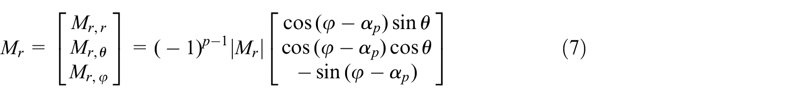
where,
The boundary conditions of the permanent magnet rotor are set:
a. The magnetic induction at infinity is 0:

b. The magnetic induction at the origin is a finite value:

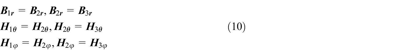
c. The magnetic induction tangential and radial components at the interface of the medium are continuous:
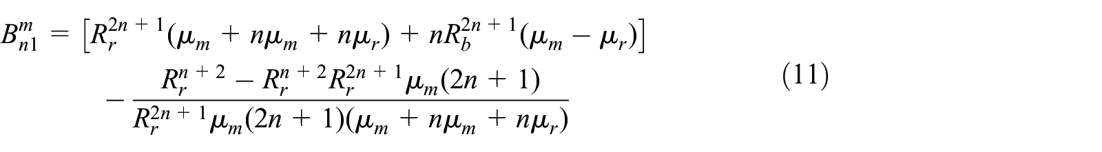
The coefficient Am n1 = 0 can be obtained by the above boundary conditions, and the expression of the coefficient Bm n1 is as follows:
The scalar magnetic special solution is:

where


where, Ymn(θ, φ) is a spherical harmonic function, and Pm n is a coupled Legendre function.
Solved by the equations (3), (5), (12):


Through the above boundary conditions, the special solution of the specific magnetic mark can be obtained, and then the air gap magnetic fundamental wave expression of the motor can be calculated:

Electromagnetic drive torque model
The magnetic field generated by the permanent magnet on the rotor interacts with the magnetic field generated by the energized coil of the stator to generate the Lorentz force of interaction. The electromagnetic force generated by the micro-component dl on each energized coil is:

The torque generated by the micro element dl is:

The driving torque generated by the electromagnetic drive is
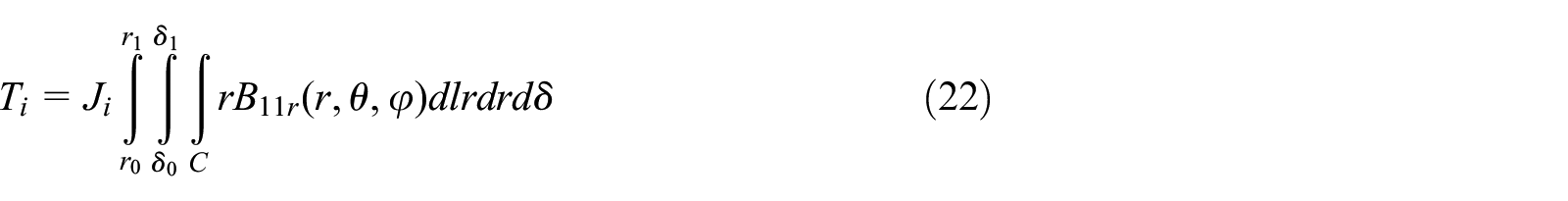
where Ji is the surface current density of the coil, r0 and r1 are the outer diameter of the permanent magnet and the inner diameter of the coil, respectively, and δ0 and δ1 are equivalent coil thicknesses, as shown in Figure 2.

Electromagnetic stator-rotor part equivalent diagram.
Convert the spherical coordinate system component in the above equation to the Cartesian coordinate system:

Let the unit vectors in the Cartesian coordinate system be eθi and eφi, and the micro-elements dl can be decomposed in the Cartesian coordinate system as:

Since the electromagnetic force of the radial component passing through the center of the sphere can drive the motor to rotate, the electromagnetic force of the circumferential component cannot drive the rotation of the motor, so the electromagnetic torque is only related to the radial component. At this time, the electromagnetic torque is expressed as:

where i is the coil number (i = 1, 2, 3…18).
The total torque produced by all coils is:

Piezoelectric drive model
The piezoelectric driving part is composed of three traveling wave inside the rotor stators and a spherical rotor. The structure and coordinate system is shown in Figure 3, part a shows the structure of the piezoelectric driving portion, and part b shows the inclination angle of the piezoelectric stators. The coordinate system is three-dimensional Cartesian coordinate system, the z-axis is vertical upward, the axis1 is located in the xoz plane, the three stators are symmetrically distributed along the output axis at an angle of 120°, and the angle between the axis1 and the x-axis is α.

Piezoelectric drive internal structure and coordinate system: (a) piezoelectric drive space coordinate system and (b) the angle between the piezoelectric stators and the horizontal plane.
The piezoelectric ceramic part is divided into two phases which are spatially symmetric, the two-phase piezoelectric ceramics are polarized in the thickness direction and the adjacent portions are oppositely polarized, and the inner edge of the spherical rotor is coated with a friction material. Applying an alternating voltage with a phase difference of 90° to the two-phase piezoelectric ceramic, due to the inverse piezoelectric effect of the piezoelectric ceramic and the phase difference between the two-phase vibration time and space, the adjacent ceramic sheets generate a traveling wave. The stator traveling wave transmits energy to the rotor to drive the rotor through the friction layer to make a rotary motion, and the moving direction of the rotor and the traveling direction of the traveling wave are opposite.
The traveling wave excitation voltage is applied to the three stators at the same time, and the three stators will generate driving torque to the spherical rotor. Since the three stators are not coplanar, the spherical rotor can generate any direction under the action of three driving torques. The rotary motion realizes the three-degree-of-freedom movement of the motor.
Contact model of stator and rotor
The piezoelectric ceramic sheets are divided into two groups, A and B, as shown in Figure 4(a).The polarization of all piezoelectric ceramic sheets is along the thickness direction, and the polarization direction of adjacent piezoelectric ceramics is opposite. The gap is a nonpolarized piezoelectric ceramic sheet.

(a) Arrangement and polarization of piezoelectric ceramic sheets and (b) sectional view of support structure.
Sectional view of support structure is shown in Figure 4(b).The stators are fixedly connected to the support body through three bolts, the lower end of the fixtures is fixedly connected to the base through threads, and the upper part includes three openings that are symmetrically distributed in space. The support structure is composed of support, fixtures and pre-pressure rod. By adjusting the height of the pre-tightening rod and the pre pressure of the three traveling wave stators, the pre pressure is equal.
Considering that there are many nonlinear factors and uncertainties in the stator-rotor contact interface of the piezoelectric driving part, the following assumptions are made:
Assume that the stator and rotor of the motor are rigid;
Ignoring the influence of the stator cogging, it is considered that the stator surface and the friction layer are continuous.
A stator-rotor contact model of the piezoelectric driving portion is established. As shown in Figure 5, since the circumferential contact length between the stator and the rotor is much larger than the radial contact width, the three-dimensional problem can be two-dimensionally processed.
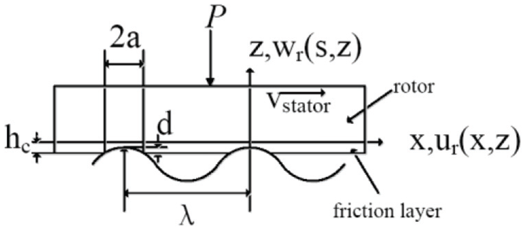
Stator-rotor contact model.
Under the action of pre-pressure P and excitation voltage, the contact area is symmetrically distributed around the traveling wave peak and moves with the traveling wave, so a (x, y, z) coordinate that moves with the traveling wave at the same speed and is relatively stationary with the traveling wave is established. The traveling wave expression is:

where A is the traveling wave amplitude, λ is the traveling wave wavelength, and ω is the vibration angular frequency.
Set the distance from the upper surface of the subsurface to the neutral layer to hct. According to the elastic theory, the tangential velocity of the surface of the stator surface is:

The stress and strain distribution of the contact layer can be obtained by the displacement function in mechanics. The displacement function is assumed to be:

where u (x, z) and w (x, z) represent the tangential displacement and normal displacement of the contact layer, respectively.
Since the friction layer is located at the inner edge of the spherical rotor, the upper surface of the contact layer is combined with the lower surface of the rotor, so at z = 0, the contact layer does not strain in the tangential direction and the normal direction, that is, u (x, 0) = w (x, 0) = 0, substituted into the equation (10) to obtain A (x) = J(x) = 0, the displacement function expression is:

At the lower surface of the contact layer, 15 w (x,-hc) = A[cos (2πx/λ)−cos (2πa/λ)], we can obtain:

where hc represents the thickness of the friction layer.
The function of displacement and strain is as follows:

From the relationship between strain and stress:

where G is the shear modulus and v is the Poisson’s ratio.
Since the circumferential contact length of the contact layer is much larger than the axial contact width and the radial vibration is not the main form of vibration, the y-axis strain is ignored, that is, εy = 0. Using stress analysis, the equilibrium equation generated in the x direction is:

where
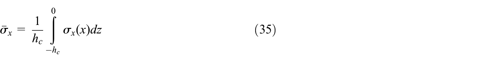
Bringing equations (33) and (35) into equation (34) yields:

Solving equation (36) gives:

The contact layer has zero strain at (±a, -hc), that is, εx(a, -hc) = 0 and εx(-a, -hc) = 0, and bringing equation (36) into equation (32) yields: c1 = Acos(2πa/λ)/(hc2(1–v)), c2 is determined by the slip state within the contact area.
The magnitude of the normal pressure of the contact area is represented by p(x), and its value is equal to σz:

Since p(x) is the normal pressure per unit length, therefore, integrating p(x) in the contact area can obtain the overall normal pressure of the stator, that is, the pre-pressure P:

According to the friction drive model, the friction factor is linear with the relative speed of the roller and the plate. The friction is expressed as 27 :

where cd is the stator circumferential friction factor, its direction as shown in Figure 6, the magnitude is determined experimentally, ωs is the stator rotational angular velocity, ωr is the rotor rotational angular velocity, and ωr can be obtained by measurement.

Radial friction factor and circumferential friction factor distribution.
Piezoelectric drive torque
Stator angular velocity analysis
The stator angular velocity is obtained by superposition of the angular velocity vectors of the three stators. Firstly, an orthogonal coordinate system as shown in Figure 3 is established for the piezoelectric driving portion. The three stator axes are circumferentially symmetrically distributed and at an angle a to the xoy plane. The resultant vector of the stator angular velocity is determined by the component vectors of the three stator angular velocity vectors in the x-axis, the y-axis, and the z-axis, respectively, therefore, the piezoelectric driving portion can rotate the motor around the x-axis, the y-axis, and the z-axis. The origin of the coordinate system is located in the center of the sphere, the z-axis is in the vertical direction, the axis of the stator S1 is in the xoz plane, and the y-axis is perpendicular to the xoz plane. The sub-angle velocity synthesis vector is set to ωt, and the components in the direction of the stator axes S1, S2, and S3 are ω1, ω2, and ω3, respectively, and the expression is:

where ω1, ω2, and ω3 are scalars, the magnitude of which is determined by the magnitude, frequency, and phase difference of the excitation voltage applied to the stator.


where the conversion matrices are:
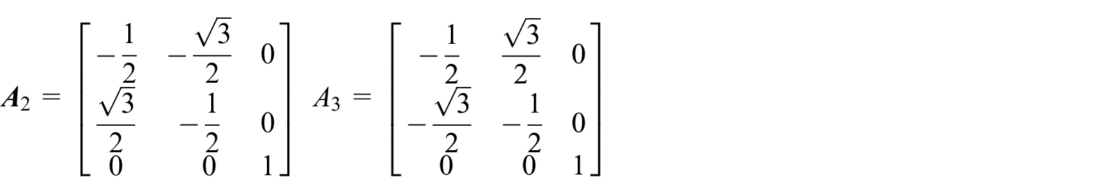
From equations (41)–(43), the angular velocity vector ωt of the piezoelectrically driven stator can be expressed as:

Therefore, the resultant angular velocity vector ωt of the piezoelectric stators can be calculated from the angle between the three stator axes and the xoy plane and the three stator angular velocity scalars.
Piezoelectric drive model
When the spherical rotor rotates, it is affected by the friction of the contact surface, so the piezoelectric driven model includes the frictional moments from the three stators and the angular velocity vector relationship of the stator. Establish a plane rectangular coordinate system XOY, let ω denotes the angular velocity vector of the spherical rotor, which is at an angle of ψ1 to the axis of the stator S1, as shown in Figure 7.

Angular velocity and torque of the rotor.
The rotor angular velocity vector is ω. It is defined that the angular velocity of the stator S1 is ω1, and the contact radius of the stator S1 is r. The pre-pressure between the stator and the spherical rotor is P. The total torque

where
The driving torque Ta1 can be expressed as:

The friction resistance torque Tf1 expression is:

where cd is the circumferential friction factor and cr is the radial friction factor, as shown in Figure 6.
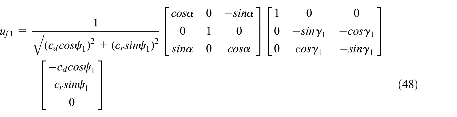
Solving the equation (48) can be obtained:

where γ1 is the angle between the plane of the stator S1 coordinate system and the z-axis. The

where, ψ1, ψ2, ψ3 can be obtained by geometric relationship according to the angular velocity direction of the piezoelectric driving part.
The torque

The angle between the rotor angular velocity direction vector and the stator S2 axis is ψ3, which can be obtained:

The load torque expression of the piezoelectric drive section is:

where θ is the angle between the load torque and the z-axis, and φ is the angle between the projection of the load torque on the xoy plane and the x-axis.
At this time, the equivalent torques on the three piezoelectric stators are:

The torque of the piezoelectric drive part is:

Electromagnetic piezoelectric hybrid drive three-degree-of-freedom motor contact state analysis
The electromagnetic piezoelectric hybrid drive three-degree-of-freedom motor has two parts: electromagnetic drive and piezoelectric drive. The combined torque of the two drive parts and the load realizes the torque balance of the three-degree-of-freedom motor. The piezoelectric driving torque is a function of the friction force, and the electromagnetic driving torque can be equivalently converted into the piezoelectric driving torque according to the spatial geometric relationship. The driving friction and frictional resistance are perpendicular to the radial direction of the piezoelectric stators, that is, the angle is 90°. According to the torque equation T = F × r, the friction force F = T/r. On the other hand, from the above analysis, it can be known that the force provided by the drive can be decomposed into the force that pushes the rotor and the force that hinders the movement of the rotor. Therefore, the frictional force of the contact surface can be obtained by solving the superimposed torque of different torques, and then the frictional distribution of the contact surface is obtained by the friction model.
The electromagnetic friction hybrid drive three-degree-of-freedom motor has different frictional force distributions at different contact states. After adding the load, the equations (54) and (55) show that the motor has different motion states, so the contact state distribution also changes. The motion state of the three-degree-of-freedom motor can be divided into the following categories: blocking movement; electromagnetic piezoelectric drive deflection motion; electromagnetic piezoelectric hybrid drive rotation motion; motion with load.
Friction model
The two objects contact under the action of normal pressure and are subjected to tangential friction. The normal pressure distribution is Hertz contact theory. The tangential force is obtained by Mindlin theory. The calculated value is similar to the elastic object in steady state. When the elastic is stability, it is assumed that the contact pressure remains the same.
It is assumed that the radial contact width is very small compared to the axial contact width. The normal pressure distribution obtained by Hertz contact theory is:

where p0 is the normal pressure maximum, that is, the value of p(x) when x = 0, and a is half the length of the contact surface of the friction layer.
During the operation of the motor, there are both friction driving force and frictional resistance at the friction layer. At any speed, the vector and maximum value are bigger than the static friction force at the same speed. According to Mindlin theory, the tangential force distribution of the friction layer contact surface can be expressed as:

where a is half of the contact length between a wave crest of the piezoelectric stator and the rotor, c is the function of the actual friction force F of the friction layer, and c is the turning point between the central sticking zone and the sliding zone in the contact area, the intervals [-a, -c] and [c, a] denote the sliding zone, the interval [-c, c] represents the central sticking zone the expression is: c/a = √(1–(Fmax-F)/2μP). According to Figure 7 and the analysis of electromagnetic torque and load torque, Fmaxis the maximum friction of the stator, and its magnitude is the sum of the circumferential drive friction, the radial friction vector and the electromagnetic drive torque vector, and F is the current actual friction, that is, the vector sum of all the torques, and μ is the friction factor at the current speed.
Blocking movement
When only the electromagnetic drive excitation is applied to the motor, if the motor is in the locked state, the contact layer has no friction; when the piezoelectric drive excitation is applied to the motor, if the motor is in the locked state, that is, ω = 0, the stator-rotor contact layer only frictional resistance. The torque expression is:

At this time, the frictional force distribution can be obtained by the equation T = F × r and the friction model.
It can be known from equation (58) that when the excitation voltages applied to the three stators are of the same frequency and the same amplitude, the angular velocities of the three stators are equal, and the maximum torques of the x-axis, the y-axis, and the z-axis are respectively:

Electromagnetic drive no-load drive
When the electromagnetic drive is driven alone without load, the motor moves in a single degree-of-freedom around the z-axis. At this time, the electromagnetic torque can be expressed as T4 = [0;0;Te]T. According to equation (53), the motor torque can be equivalently decomposed into three stator axis directions, and the equivalent torque expression is:

Therefore, the three piezoelectric stators have the same contact state and the same surface friction. Since the traveling speed of the piezoelectric stators are 0, that is, ωs = 0, the contact layer has only frictional resistance, and its magnitude is determined by the rotational speed of the spherical rotor. The friction state can be obtained from the equation T = F × r and the friction model.
Piezoelectric drive deflection motion
Generally, there are three ways to adjust the motor speed: voltage regulation, frequency modulation, and phase difference regulation. For ultrasonic motors, the phase difference regulation is generally used. 19
If the three-phase excitation voltages have the same amplitude, the same frequency, and the same phase difference, the three-phase stator produces equal-sized, identical-direction traveling waves, and the torque is spatially symmetric. The three-degree-of-freedom motor makes a single degree-of-freedom around the z-axis.
If the phase difference of the three-phase excitation voltage is not equal, the three-phase stator generates different traveling waves, and the torque is also asymmetrical. At this time, the three-degree-of-freedom motor generates deflection movement, and the moving direction is determined according to the applied three-phase excitation voltage. This torque expression is given by equations (45)–(52), and the frictional force distribution can be obtained from the equation T = F × r and the friction model.
Electromagnetic piezoelectric hybrid drive rotation motion
Since the electromagnetic drive only generates the rotation driving torque, when the electromagnetic driving and the piezoelectric driving work simultaneously, the torque generated by the piezoelectric driving should also be the rotation torque, that is, a three-phase symmetrical excitation voltage is applied to the piezoelectric stators so that the torque generated by the piezoelectric drive is parallel to the direction of the torque generated by the electromagnetic drive. The electromagnetic torque is decomposed into three equal-sized components along the stator axis. As shown in equation (60), the piezoelectric drive torque is as shown in equations (45)–(52). The torque is expressed as:

where, ψ is the angle between the three-degree-of-freedom motor speed direction and the stator axial direction. The frictional force distribution can be obtained by the equation T = F × r and the friction model.
Motion with load
The load torque can be decomposed into three stator shaft directions by the equation (60), and the torque generated by different driving modes is superposed to form the stator torque. When the load torque is parallel to the z-axis, its decomposition torque in the direction of the three stator axes is the same as the equation (60), and the magnitude is
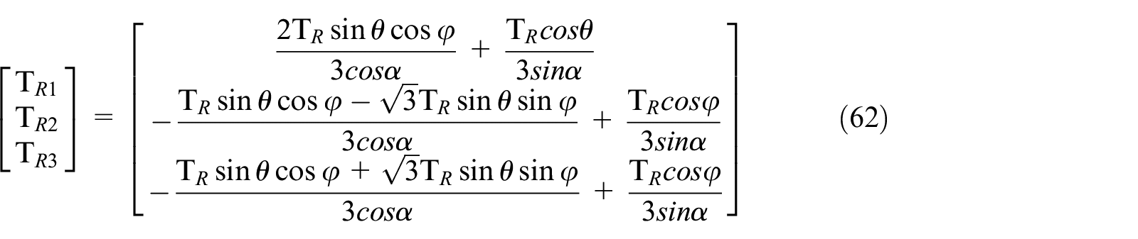
where θ is the angle with the z-axis and φ is the angle between the projection of the xoy plane and the x-axis.
Therefore, the load torque whose torque direction is not parallel to the z-axis has different effects on the three stator contact states. After the equivalent transformation, the resultant torque is equivalent to the vector sum of the driving torque and the load torque. The driving torque and the resistance torque of the piezoelectric stators are obtained by the equations (45)–(52). The frictional force distribution can be obtained by the equation T = F × r and the friction model.
Electromagnetic piezoelectric hybrid drive three-degree-of-freedom motor contact state calculation
In this experiment, a three-degree-of-freedom piezoelectric driving prototype was fabricated, and its structure is shown in Figure 8. The parameters of the hybrid drive multi-degree-of-freedom motor are shown in Table 1

The structure of the prototype motor: (a) motor appearance and (b) internal structure of the motor.
Motor parameters.

In order to measure the rotational speed of the prototype under different conditions, firstly, the impedance is analyzed by the impedance analyzer (HT2829A, Tonghui, China), The impedance analyzer fixture is respectively connected to the energizing end and the grounding end of the prototype stator, as shown in Figure 9, so that the relationship between the impedance and the frequency of the piezoelectric stator can be measured, the resonant frequency of the stator is obtained, and the maximum output performance is realized to facilitate the measurement. The impedance-frequency relationship of the stator is shown in Figure 10.

Prototype impedance-phase measurement platform.

Impedance-frequency relationship diagram of the prototype.
Since each stator has two-phase piezoelectric ceramics, the measurement results of the two-phase piezoelectric ceramics are consistent; for the three stators, the test results also have slight deviations due to the asymmetry caused by the small errors in fabrication and installation. Therefore, the three stators were tested respectively, and the resonant frequencies are 40.350, 40.360, and 40.365 kHz, respectively. Therefore, the voltage frequency uses its average value of 40.358 kHz.
Then, the frequency of the driving voltage is adjusted to the resonant frequency by the upper computer, and the rotational speed and Euler angle of the prototype are recorded in real time through the MPU-9250 nine-axis attitude sensor. The experimental platform is shown in Figure 12. Since the output performance of the piezoelectric drive was adjusted by the voltage regulation to have the best linear correlation, the relationship between the rotational speed and the driving voltage amplitude of the piezoelectric driving device was tested, and the result is shown in Figure 11, the electromagnetic drive part works under rated voltage, and the rotor speed is 77.3 r/min under no-load condition.

Prototype speed-voltage diagram.
In order to make the results more obvious, according to the above experiment, the following are the calculations of the motor speed tested by the prototype at a voltage amplitude of 400 V and a voltage frequency of 40.356 kHz.
Based on the derivation in the second and third sections, as well as the rotational speed and deflection angle obtained from the experiment shown in Figure 12, the friction distribution of the friction layer between the piezoelectric stator and rotor under different driving and motion states can be obtained.

Prototype performance test platform.
Blocking movement
When the piezoelectric drive excitation is applied to a three-degree-of-freedom hybrid drive motor and the motor is in a locked state, since the rotor speed is zero, the stator-rotor contact layer only has frictional resistance, and since the average relative rotational speed between the stator and the rotor is the largest, the block is blocked. The average friction of the contact layer is the highest in the rotating state. The frictional force distribution is shown in Figure 13.
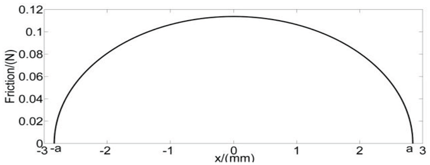
Friction distribution of contact layer when piezoelectric drive is blocked.
Electromagnetic drive alone drive
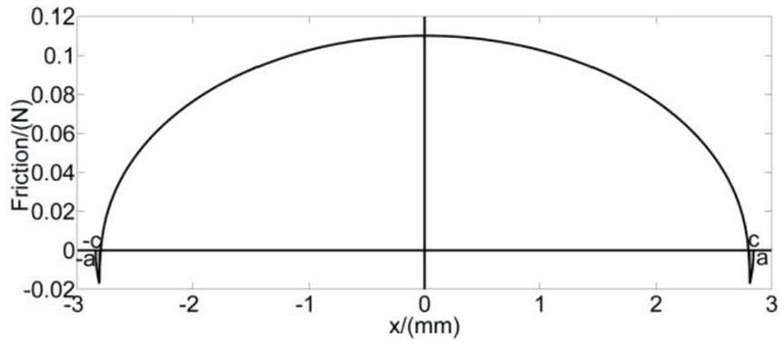
The three-degree-of-freedom hybrid drive motor is driven by electromagnetic rotation and no piezoelectric excitation is applied. At this time, the traveling speed of the piezoelectric stators are 0, and the rotor speed is not zero. This situation is similar to the stalling state, and the piezoelectric stators have frictional resistance only to the spherical rotor. Since the rotational speed of the rotor driven by the electromagnetic alone is smaller than the traveling speed of the piezoelectric stators when the piezoelectric drive is driven, the frictional force of the contact surface when the electromagnetic single drive is smaller than the locked state, and the frictional force distribution is as shown in Figure 14.

Friction distribution of contact layer when piezoelectric drive is blocked.
Piezoelectric symmetrical drive
Three sets of AC voltages with equal amplitude, equal frequency and equal phase difference are applied to the piezoelectric stators. Since the three-phase stator is spatially symmetric, the three-phase torque is also symmetric about the z-axis. The equation (58) can be used to obtain that the output torque of the prototype is parallel to the z-axis, and the prototype realizes the rotation around the z-axis. In addition, the relative speeds of the piezoelectric stators and the spherical rotor and pre-stress are the same, so the three piezoelectric stators-rotor contact states are the same. The frictional force distribution is shown in Figure 15.

Contact layer friction distribution when electromagnetic drive is driven separately.
Piezoelectric drive asymmetric drive
Three sets of asymmetric excitation voltages are applied to the piezoelectric stators, at which point the magnitude and direction of the torque generated by the piezoelectric stators are asymmetrical. The total output torque of the prototype is not parallel to the z-axis, the motor is deflected, and the direction of deflection is consistent with the direction of the total output torque of the prototype. When the output axis is located in the xoz plane, the angle between output axis and z axis is 27.4°, and y axis is 22.3°, the friction distribution of the three-phase stator contact layer is as shown in Figures 16 to 18.

Friction distribution of contact layer of stator S1 when asymmetric excitation voltage is applied.

Friction distribution of contact layer of stator S2 when asymmetric excitation voltage is applied
Friction distribution of contact layer of stator S3 when asymmetric excitation voltage is applied.
It can be intuitively obtained from Figures 15 to 17 that the frictional force and the distribution of the contact faces of the three piezoelectric stators are different, and since the rotation direction of the stator S2 is −94.32°, the frictional force of the contact surface of the stator S2 is The spherical rotor is almost pure frictional resistance, reducing the output performance of the prototype.
Electromagnetic piezoelectric hybrid drive
When the electromagnetic drive drives the prototype under rated conditions and three sets of the same voltage, the same frequency and the same phase difference of the AC voltage are applied to the piezoelectric stators, the electromagnetic drive torque and the total output torque generated by the piezoelectric drive are in the same direction and both parallel to the z-axis, the two drive torque super positions are the total output torque of the prototype. In this case, the rotational speed of the spherical rotor is the fastest, so the average relative velocity of the spherical rotor and the piezoelectric stators are the smallest, the average friction is the smallest, and the frictional force distribution is as shown in Figure 19.

Friction distribution of contact layer of stator when asymmetric excitation voltage is applied.
Hybrid drive with load
Three sets of the same voltage, the same frequency, the same phase difference of the AC voltage are applied to the piezoelectric stators, and the excitation in the rated state is applied to the electromagnetic drive portion, and a load of 120 Nmm torque is applied to the output shaft of the prototype. At this time, the prototype is a self-rotating motion with a load. Due to the influence of the load on the motion state of the prototype, the rotational speed of the prototype is reduced, but the speed of the traveling wave of the piezoelectric stators are constant, which causes the relative speed of the spherical rotor and the piezoelectric stators to be lower than that under no load, therefore, the frictional force of the piezoelectric stators-rotor contact surface is increased, and the frictional force distribution is as shown in Figure 20.

Friction distribution of contact layer of stator in hybrid drive with load.
Conclusion
One of the keys to establishing a dynamic model of an electromagnetic piezoelectric hybrid drive three-degree-of-freedom motor coupling system is the piezoelectric stators-rotor interface contact model. Electromagnetic piezoelectric hybrid drive three-degree-of-freedom motor has multiple driving modes. The driving mode, excitation voltage and load of the motor are different, the motion state and torque of the motor are also different. The frictional distribution of the contact layer of the three stators is obtained by the piezoelectric torque and friction theory, which provides a basis for the further optimization of the friction interface.
Firstly, the basic principle and structure of the hybrid drive three-degree-of-freedom motor are introduced. The electromagnetic-driven air-gap magnetic field model is established, and the electromagnetic drive torque is obtained by analytical method. Static analysis of the piezoelectric driven stator-rotor is carried out, and then the piezoelectric driving torque is vector analyzed by spatial geometric relationship. The electromagnetic torque and piezoelectric torque are superimposed, and the distribution of stator torque under different driving conditions is analyzed. By analyzing the non-elastic moving contact, the Hertz contact theory and Mindlin theory are applied to analyze the distribution of friction of the contact layer, the friction interface model considering the nonlinear part is established. Finally, Matlab is used to obtain the contact surface friction distribution diagram of the hybrid drive three-degree-of-freedom motor under different driving and motion states.
Through detailed analysis of the torque of the hybrid drive motor, it can be concluded that the four drive torques will affect the contact state. The four driving torque states determine the final contact state by the piezoelectric stators angular velocity, the spherical rotor angular velocity vector and the load condition, the relative speed of the piezoelectric stators and the spherical rotor is proportional to the frictional force. In summary, the feasibility of three-degree-of-freedom of hybrid drive motor is verified. The friction distribution of contact layer under different driving and load conditions is analyzed. It provides a basis for understanding the stator-rotor contact drive mechanism and the further optimization of friction interface, which provides the foundation for further design and performance improvement.
Footnotes
Declaration of conflicting interests
The author(s) declared no potential conflicts of interest with respect to the research, authorship, and/or publication of this article.
Funding
The author(s) disclosed receipt of the following financial support for the research, authorship, and/or publication of this article: This work is supported by the National Natural Science Foundation of China (No. 51877070, 51577048,), the Natural Science Foundation of Hebei Province of China (No. E2018208155), the Talent Engineering Training Support Project of Hebei Province (A201905008), the National Engineering Laboratory of Energy-saving Motor & Control Technique, Anhui University (No. KFKT201901), Hebei Province Graduate Innovation Funding Project (CXZZSS2019084).