
Abstract
The existing nano-positioning stages are driven by the piezoelectric ceramics, which have features of high accuracy and resolution, but the traditional positioning stage could not meet the requirement of large working space because the displacement of the piezoelectric ceramics is only tens of microns. To solve the contradiction between high accuracy and large working space, a novel non-resonant piezoelectric linear actuator, which adopted the two parallel v-shaped stators as the double driving feet, was proposed, and both its working principle and structure were discussed in detail. The actuator was used to drive the positioning stage directly to obtain the performance of nano-positioning and large working stroke. The experiment results show that the resolution of the actuator is 0.015 μm, and its stable maximum motion speed is 17.4 mm/s, while the degree-of-freedom of step resolution of teach nano-positioning stage is 0.018 μm, 0.016 μm, and 0.3 μrad, respectively. Compared with the traditional positioning stage, the nano-positioning stage driven by the actuators directly also has excellent working stroke. The key performance of both high resolution and large working stroke of the nano-positioning stage was realized based on different motion modes of only one piezoelectric actuator.
Introduction
With the rapid development of the nanometer technology, 1 microelectronics industry, 2 bioengineering,3,4 aerospace, 5 and other disciplines, research on nano-scale is getting more and more important, and many disciplines have entered nano-scale. Therefore, the devices with nano-scale operational accuracy have become the key equipment. In the field of optical devices and optical engineering, the multi-degree-of-freedom (DOF) nano-positioning stage is becoming the key performance equipment. The requirements of the operation stage or the positioning stage are becoming much more strict, and the most important index of performance is high resolution and large working stroke. 6 Precision positioning stage with multi-DOF has been studied widely in recent years. The current nano-positioning stages are almost driven by the piezoelectric ceramics, which has the advantages of high accuracy and resolution, but its displacement is only tens of microns, and it is difficult to meet the needs of large working space. To make up the defects of small displacement of piezoelectric ceramics, the displacement amplification mechanism is arranged between the piezoelectric ceramics and the positioning platform. The lever amplification mechanism, 7 differential amplifier, 8 and bridge type amplification mechanism 9 are the most frequently used. However, it is noteworthy that the displacement magnification mechanism reduces the positioning accuracy while enlarging the working stroke of the piezoelectric actuator. Therefore, the requirements of high accuracy and large working space become a contradiction.
To solve this contradiction and make the nano-positioning stage satisfy the requirements of large working space and high accuracy at the same time, many scholars proposed and studied the serial-parallel positioning stages. 10 In addition, Sun and Dong 11 proposed the flexure hinge with large displacement, and applied it in the parallel positioning platform; Li and Li 12 studied the new flexible parallel mechanism with 3-P(4S) based on the flexure hinge with large displacement; Xu 13 developed a XY positioning mechanism with large working space by taking use of the variable stiffness principle; Shayya et al. 14 proposed the 5-DOF parallel positioning manipulator by the prismatic actuator; Shan et al. 15 discussed the vertical precision positioning system using ultrasonic linear actuator; Olfatnia et al. 16 designed the electrostatic comb driver for the application of positioning mechanism with large working space. Summarizing the above mentioned studies, the serial-parallel positioning platform, or the new designed flexure hinge with large displacement, or the new actuator with large working space, the applications of them are still limited because of the large structure or the complex control model.
Aiming at solving the contradiction between the high accuracy and large working space, a nano-positioning stage, driven directly by the piezoelectric actuator, was proposed by making use of the two working modes of the piezoelectric actuator. Specifically speaking, the two working modes were the continuous motion mode and the step motion mode. The continuous motion mode could realize the macro-motion with large working space and the step motion mode is responsible for the nano-positioning with high accuracy. Obviously, the transmission chain is shortened greatly, the responsible speed is improved, and the control is also simplified. Therefore, the nano-positioning stage could satisfy both the requirements of high accuracy and large working space. The development of optical, biomedical, and other technologies has placed increasing demands on the accuracy and working range of positioning stages. The positioning stage with capabilities of high-precision and large working range can greatly improve the engineering application level. The method proposed in this article, which adopted non-resonant piezoelectric actuators to directly drive the positioning mechanism and achieve the high resolution and large working range, would provide a new way for the engineering application of precision actuation and control technology.
Design of the piezoelectric actuator
Structure design
Considering that the traditional single v-shaped stator structure had a well-known performance, 17 the v-shaped stator was used in the optimized piezoelectric actuator, which worked at the non-resonant frequency and had better stable resolution. The non-resonant piezoelectric linear actuator adopted two parallel v-shaped stators to form the double driving feet, and the two parallel stators were fixed into the guide box by assembly screws. The guide box was responsible for restraining the motion of other axes. The single stator was composed of the driving foot, piezoelectric stack, cushion block, bracket, elastic beam, pre-tightening bolts, and clamping device. The cushion block was used to adjust the clearance between the piezoelectric stack and the driving foot. The elastic beam and the pre-tightening bolts could support the suitable pre-tightening force to guarantee the piezoelectric stack the best performance. The structure of the stator was shown in Figure 1.

Diagram of non-resonant piezoelectric linear actuator: (a) structure of stator, (b) specimen of stator, and (c) assembly of actuator.
There were four piezoelectric stacks, marked as a1, a2, a3, and a4, respectively, and were divided into two groups. In the actual arrangement, the piezoelectric stacks a1 and a2 were fixed in the stator 1 and the piezoelectric stacks a3 and a4 were fixed in the stator 2. Therefore, the driving feet of the two stators could generate motion only if the two groups of piezoelectric stacks were driven by the suitable excitation signal.
Working principle
According to the literature, 18 under the excitation of sine signal, the displacement curve of piezoelectric stack is similar to the sine wave, and the deformation of piezoelectric stack is linear to the driving voltage in the low-frequency band. Therefore, the excitation of sine signal that excited onto the four piezoelectric stacks was as follows

where A is the voltage amplitude and ωt is the phase.
However, the deformation of the piezoelectric stack is 18

where α is a constant coefficient, u is the voltage value.
Obviously, the displacement of the four piezoelectric stacks was as follows

The parameter t of formula (3) could be eliminated, and the conclusion could be obtained as follows

Because the piezoelectric stacks 1 and 2 were fixed in the same stator, and the piezoelectric stacks 3 and 4 were fixed in the other stator, formula (4) shows that the trajectory of the driving foot of every stator is ellipse. The two groups of piezoelectric stacks were placed orthogonally in space, and the excitation signal of the two groups of the piezoelectric stack differed 90° in phase, thus any one of the two driving feet could touch and drive the mover alternately at any time. The excitation signal was shown in Figure 2 and the movement principle of the stator in one period was illustrated in Figure 3.

The excitation signal.
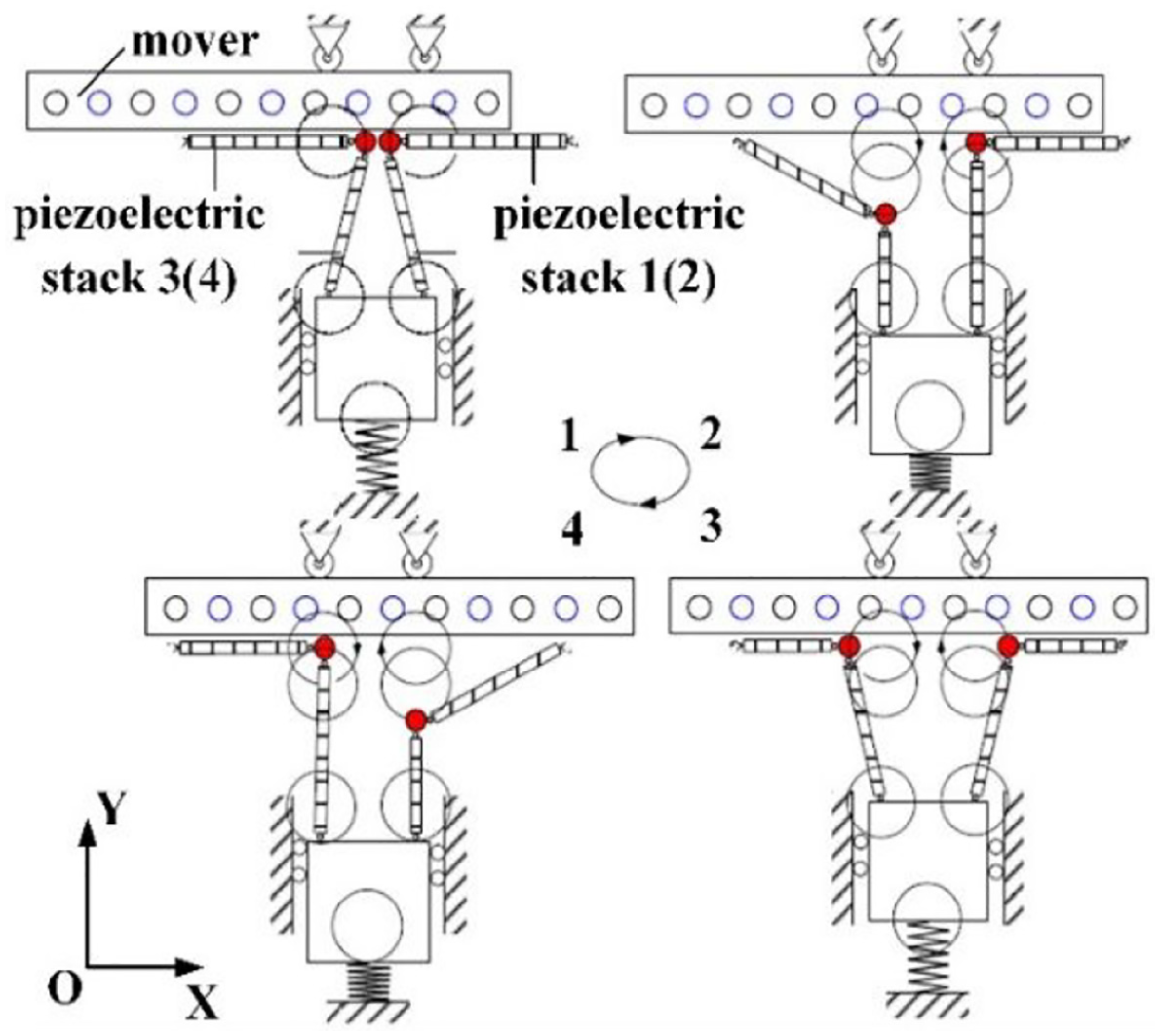
Principle of stators in one period.
There were four stages in the stators’ movement in one period, and the movement principle of stators in one period was discussed in detail.
The first stage (0–1/4T): The piezoelectric stack 1 vibrated longitudinally, and it deformed from αA to the maximum deformation of 2αA. The piezoelectric stack 3 vibrated longitudinally, and it deformed from αA to the minimum deformation of 0. Therefore, the driving foot 1 contacted the mover, while the driving foot 2 separated away from the mover. The piezoelectric stack 2 vibrated horizontally, and it deformed from 2αA to αA along the right direction. At this stage, the mover was driven to the right.
The second stage (1/4T–1/2T): The piezoelectric stack 1 vibrated longitudinally, and it deformed from 2αA to αA. The piezoelectric stack 3 vibrated longitudinally, and it deformed from 0 to αA. Therefore, the driving foot 1 still contacted the mover, while the driving foot 2 separated away from the mover. The piezoelectric stack 2 vibrated horizontally, and it deformed from αA to 0 along the right direction. At this stage, the mover was driven to the right.
The third stage (1/2T–3/4T): The piezoelectric stack 1 vibrated longitudinally, and it deformed from αA to 0. The piezoelectric stack 3 vibrated longitudinally, and it deformed from αA to 2αA. Therefore, the driving foot 1 separated away from the mover, while the driving foot 2 contacted the mover. The piezoelectric stack 4 vibrated horizontally, and it deformed from 2αA to αA along the right direction. At this stage, the mover was still driven to the right.
The fourth stage (3/4T–T): The piezoelectric stack 1 vibrated longitudinally, and it deformed from 0 to αA. The piezoelectric stack 3 vibrated longitudinally, and it deformed from 2αA to αA. Therefore, the driving foot 1 separated away from the mover, while the driving foot 2 contacted the mover. The piezoelectric stack 4 vibrated horizontally, and it deformed from αA to 0 along the right direction. At this stage, the mover was driven to the right.
And so far, the mover was driven to realize one period of linear motion by the two driving feet, and the mover would be driven to the left when we reverse the phase difference between the piezoelectric stacks 2 and 4.
Design of the nano-positioning stage
The nano-positioning stage has 3-DOF which were established by the serial structure. The stage could realize the linear motion along the X-axis and the Y-axis and the rotation motion around the Z-axis. The 3-DOF nano-positioning stage was shown in Figure 4.

The 3-DOF nano-positioning stage.
It could be seen that the movement of each axis could be realized using the non-resonant piezoelectric linear actuator directly. Consequently, the complicated transmission mechanism and the conversion mechanism were both removed, and the inherent accumulation error in traditional serial structure could be eliminated. Obviously, the 3-DOF nano-positioning stage could meet the requirements of high accuracy and large working space synchronously.
Design of the translation platform
The structure diagram of the translation stage was shown in Figure 5. The high accuracy linear guide 5 was taken as the mover, which was driven directly by the two driving feet of the non-resonant piezoelectric linear actuator 2. To improve the driving effect and make the piezoelectric linear actuator run smoothly, a ceramic plate 3 with high hardness was used to paste on the front end of the friction pad 4, which was also pasted on the front end of the THK linear guide 5. The piezoelectric linear actuator 2 was assembled onto the baseboard 1 by pins after the two driving feet contacted the ceramic plate 3 well, and the pre-tightening force between the two driving feet (stator) and the linear guide (mover) could be adjusted by the pre-tightening bolts.
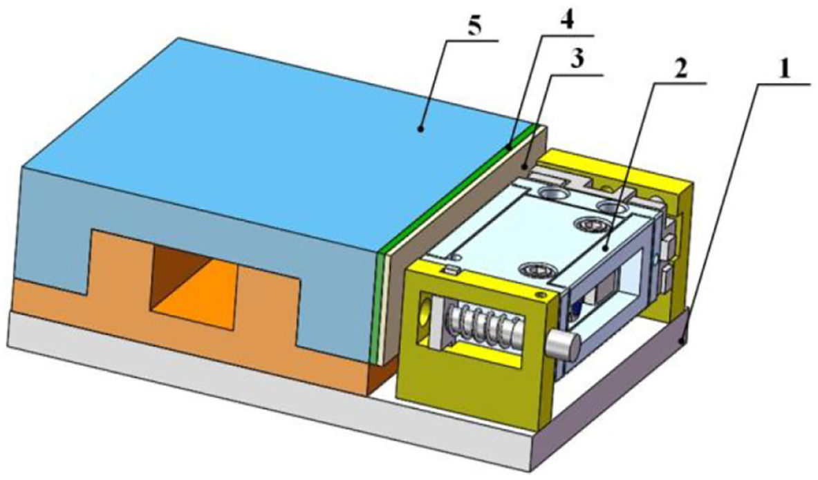
Structure of linear motion platform.
The 2-DOF translation movement along the X-axis and the Y-axis could be realized by placing the two translation platforms orthogonally, one is on the top of the other, and the upper platform should be fixed with the top surface of the lower platform.
Design of the rotation platform
The structure diagram of the rotation platform was shown in Figure 6. The rotation component 3 was taken as the mover, which was driven directly by the two driving feet of the non-resonant piezoelectric linear actuator 2. The rotation assembly 3 was composed of the rotation platform 31, the bear 32, and the rotation shaft 33. The pre-tightening force between the two driving feet (stator) and the rotation component (mover) should also be able to be adjusted by the pre-tightening bolts when assembling the rotation platform. The rotation around the Z-axis could be realized by fixing the rotation platform with the top surface of the translation platform.

Structure of rotation motion platform.
Experiment
Experiment system
The experiment system consisted of vibration isolation platform, signal generator, power amplifier, laser displacement sensor, and oscilloscope. The experiment system was shown in Figure 7. The specification and type of the main experiment devices were selected as follows:
Air floatation vibration isolation platform, ZDT10-08;
Signal generator, MHS-2300A;
Power amplifier, XE500-A4;
Oscilloscope, Tektronix DPO2014;
Laser displacement sensor, KEYENCE LK-HD500.

Diagram of experiment system.
Experiment of the piezoelectric actuator
Step motion mode
First, it is necessary to verify the output performance of the piezoelectric actuator. In practical applications, the resolution of non-resonant piezoelectric linear actuator is defined as that the piezoelectric linear actuator could output the stable minimum step size under the minimum excitation voltage.
Under the no-load situation, and when the excitation signal was selected as the sine wave, its peak-to-peak value was 10 V and its frequency was 10 Hz, the preload was set as 40 N. Figure 8 shows the resolution of the piezoelectric actuator under the step motion mode as 0.015 μm.
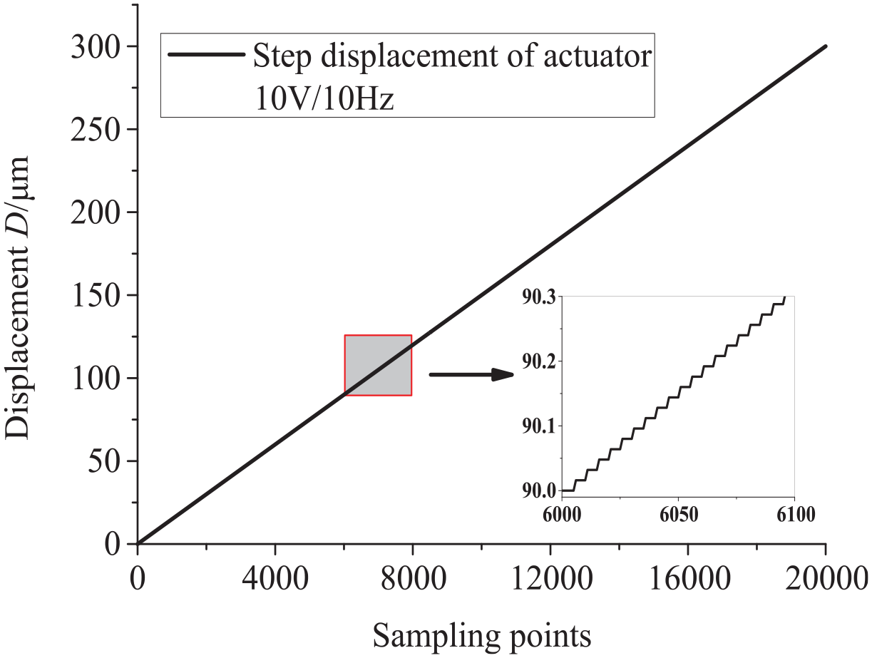
Actuator’s step resolution of the step motion mode.
Continuous motion mode
The purpose of the continuous motion of non-resonant piezoelectric linear actuator is to obtain the fast motion speed and large working stroke. Under the same experiment condition, the output motion speed of the actuator increased gradually with the increase of the peak-to-peak value and its frequency of the excitation signal. Figure 9 shows the actuator’s motion speed of the continuous motion mode.

Actuator’s motion speed of the continuous motion mode.
The excitation signal was still selected as the sine wave, the peak-to-peak value of the excitation signal was from 40 to 100 V, and the frequency was from 20 to 100 Hz. It could be found that if the peak-to-peak value of the excitation voltage and its frequency were higher, then the motion speed curve had better linearity. With the increase of the peak-to-peak value of the excitation signal, the motion speed was increasing gradually. When the excitation voltage was fixed, the motion speed also increased slowly and linearly with the increase of the frequency of the excitation voltage.
Obviously, when the peak-to-peak value of the excitation voltage was 100 V, and its frequency was 100 Hz, the motion speed curve had the best linearity. The highest motion speed was 17.4 mm/s, which was greatly helpful to generate the fast motion and obtain the large working stroke.
Experiment of the nano-positioning stage
Step motion mode
The step motion mode is responsible for the micro-positioning with high resolution. Each DOF’s step resolutions of the step driving mode were shown in Figure 10.
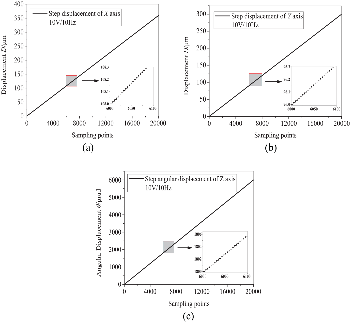
Each DOF’s step resolution of the step driving mode: (a) resolution of the X-axis; (b) resolution of the Y-axis; and (c) resolution of the Z-axis.
When the excitation signal was selected as the sine wave, and its peak-to-peak value was 10 V and its frequency was 10 Hz, the step resolution of the translation along the X-axis was 0.018 μm, the step resolution of the translation along the Y-axis was 0.016 μm under the same experiment parameters, and the step resolution of the rotation around the Z-axis was 0.3 μrad.
Continuous motion mode
It could be seen that when the peak-to-peak value of the excitation voltage was 100 V, and its frequency was 100 Hz, the actuator had the stable maximum motion speed (17.4 mm/s). Therefore, the continuous motion experiment of the nano-positioning stage could be carried out under the condition that is the same with that of the stable maximum motion speed. The experiment data shows that each DOF’s stable maximum motion speed of the nano-positioning stage is 12.88 mm/s, 14.09 mm/s, and 0.46 rad/s. Table 1 shows the key performance of each DOF of the nano-positioning stage.
The key performance of the nano-positioning stage.

Conclusion
The novel non-resonant piezoelectric linear actuator with the two motion feet based on the v-shaped stator was proposed. There were four piezoelectric stacks to compose the double driving feet (stator) and the two stators could drive alternately by the four sine waves that differed 90° in phase with each other.
The experiment results show that the resolution of the piezoelectric actuator is 0.015 μm, and its stable maximum motion speed is 17.4 mm/s, which was greatly helpful to generate the fast motion and obtain the large working stroke.
The piezoelectric linear actuator was applied into the 3-DOF precision nano-positioning stage, which was driven by the non-resonant piezoelectric linear actuator directly. The experiment results show that the nano-positioning platform has excellent ability of nano-resolution and large working range.
Footnotes
Declaration of conflicting interests
The author(s) declared no potential conflicts of interest with respect to the research, authorship, and/or publication of this article.
Funding
The author(s) disclosed receipt of the following financial support for the research, authorship, and/or publication of this article: This work was supported by National Natural Science Foundation of China (51805465 and 51405420), The Natural Science Foundation of the Jiangsu Higher Education Institutions of China (18KJB460030).