
Abstract
Based on Hertz elastic contact theory, the contact mechanics model of two cosine wave is established. The mechanical characteristics of the model in the elastic, elastic-plastic, and plastic stages were studied. The influence of load on contact deformation and other characteristics is considered. The finite element method is used to analyze the deformation process of the model, and the results are compared with those of the mechanical model. The effects of amplitude and wavelength of cosine wave on its mechanical characteristics are discussed. The results show that the model reflects the relationship between the load and the mechanical characteristics of the model, and the difference of amplitude and wavelength will affect this characteristic.
Introduction
For the contact problem of two contact bodies the calculation method is mainly the classic Hertz elastic contact theory. 1 The Hertz elastic contact theory model can calculate the stress between two contact surfaces to determine whether the contact body meets the contact strength requirements. 2 Many scholars have also established mechanical models of rough surfaces based on Hertz elastic contact theory. Among them, Greenwood and Williamson 3 established a rough surface elastic model, which predicted the effect of real contact area on normal loads. Wang et al. 4 proposed a rough surface normal contact mechanics model considering the contact load and contact area of micro convex elastic-plastic deformation based on Hertz elastic contact theory. Fu 1 considered the axisymmetric normal contact of two elastic bodies and extended the Hertz elastic contact theory to an elastic body with a polynomial profile. Machado et al. 5 compared a variety of flexible contact mechanics models and provided these contact models with information on the scope and accuracy of applications in different contact scenarios.
In the last few decades, research on regular contact models has also made related progress, including spherical contact models, cylindrical contact models and ellipsoidal contact models. Among them, Zhupanska 6 considered the normal frictionless contact problem of two identical elastic balls, which solved the contact stress and surface displacement of the sphere by the method of the mixed boundary problem, and compared it with the Hertz elastic contact theory. Mikic and Roca 7 studied the effect of roughness on the pressure distribution in the interface between two spherical surfaces. Pereira et al. 8 compared three elastic contact models of cylinders, including Johnson Model,9,10 Radzimovsky Model, 11 and Goldsmith Model, 12 which analyzed the effective domain of each model. Liu and Shao 13 and Liu 14 studied the effect of lubricating oil film and support stiffness in the cylindrical contact model, and applied it to rolling bearings. Considering the elasticity of the cylinder, the viscosity of the lubricant, the speed of the contact surface and the applied load, Kudish 15 proposed a conformal elastic hydrodynamic lubrication contact model with two infinite cylindrical surfaces with parallel axes. Halling and Nuri 16 established an elliptical concave convex surface elastic and plastic contact model based on Hertz elastic contact without traction. Wang and Zhu17–19 proposed cylindrical, ellipsoid, and spherical contact models. The contact modes of the above models are all coaxial contact, which does not consider the mechanical behavior of the contact model at different contact angles of the axis. Guo et al. 20 proposed a cylindrical elastic-plastic contact model, which considered the relevant mechanical behavior of the model at different axis contact angles.
In fact, the cosine wave contact model is also a typical contact model, but few scholars have studied it. Based on the semi-analytical method of fast viscoelastic contact algorithm, Peng and Wang 21 studied the viscoelastic contact problem of sinusoidal rough surfaces. Yuan et al. 22 established a theoretical state elastic contact model of cylindrical sinusoidal teeth based on the assumption of small elastic deformation and coordination of deformation. In the above-mentioned study of the cosine wave contact model, only the contact problem in the elastic phase is considered.
Therefore, this article will propose a cosine wave elastic-plastic contact model, which consider the mechanical characteristic of the model at different axis contact angles, and the deformation process is analyzed by finite element method.
Contact mechanics model
Full elastic stage
If the amplitude of two cosine waves is A and the wavelength is


The surface

Namely

From equations (2) and (3), the initial gap between two cosine wave surfaces can be expressed as

If the upper surface of the cosine wave model is subjected to a vertical downward load along the Z-direction, the contact deformation of the model will occur under the action of the load, and the initial point contact will gradually form the surface contact, as shown in Figure 1. The deformation of the upper and lower cosine wave models are respectively

Cosine wave model: (a) no load and (b) with load.
The contact deformation

The distance L that the two contact points approach each other is

According to equation (6) and the displacement equation of each object in semi-infinite plane 9

where
There are many unknowns in equation (7) and the polynomial at the right end is complex, which brings great difficulties to the solution. In order to solve the above equation conveniently, equation (4) can be simplified. In this paper, we choose to make a square approximation to the initial gap h and replace it with a simpler polynomial. Therefore, the simplified initial gap h can be obtained as

From equation (7), the relationship between the contact deformation

where
The curvature radius e can be obtained by this equation

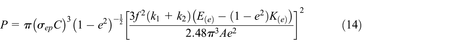
According to equation (6), the relationship between contact area S and load P can be expressed as

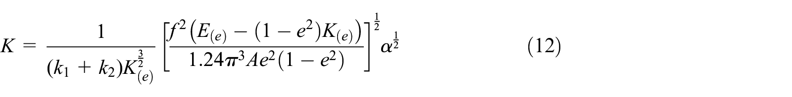
From equation (9), the contact stiffness of cosine wave surface is
Elastic-plastic stage
The cosine wave contact model begins to appear plastic deformation, but there is still elastic deformation. This deformation stage is elastic-plastic deformation stage. Green
24
found that when the two asperities began to appear elastic-plastic deformation, the maximum average contact pressure

According to equation (11), the load P of the contact model at the initial yield point can be expressed as
The displacement of the contact model at initial yield can be obtained as

where
Full plastic stage
When the cosine contact model enters the stage of complete plastic deformation, the average contact pressure can be regarded as the same as the yield strength 25

where
Based on Abbott, 26 the area of the contact model in the plastic stage is twice that of the elastic stage.

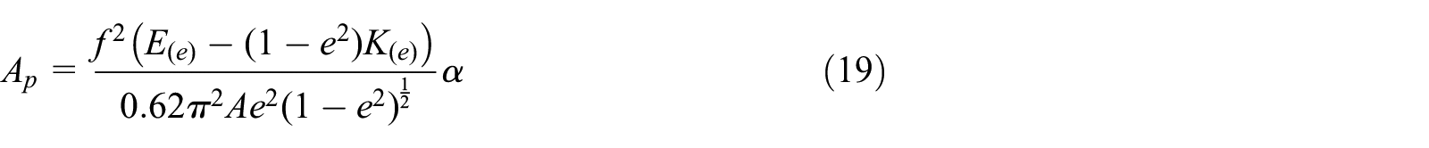
According to equations (8) and (10), the area of the model can be represented as

Then the contact area of the contact model in the fully plastic stage is
The total load P can be shown as

Namely

Then the contact stiffness of the model in the plastic stage can be expressed as

Namely

Simulation and comparison
Modeling and simulation
The cosine wave model material is steel, Young’s modulus E = 2.1 × 10⁵ MPa, Poisson ratio u = 0.3, amplitude A = 0.5 mm, wavelength f = 2 mm, yield strength σs = 350 MPa. Figure 2 shows the cosine wave mesh model with contact angles of 45°, 60°, and 90°. The mesh element type is C3D8R, totally dividing 47,160 units and 51,708 nodes. The contact mode of the contact model is surface-to-surface without considering friction, and its initial contact mode is point contact. The sliding formulation is finite sliding. The mesh density around the contact surface is increased to ensure the convergence l and promote the calculation accuracy. The minimum element size is

Mesh model: (a) 45° contact, (b) 60° contact, and (c) 90° contact.
The Y-strain cloud diagram of the cosine wave model obtained by the post-processing module is shown in Figure 3, in which the model is a 45° contact and the load is 0.1 KN. As can be seen in Figure 3(b) and (c), the deformation of the contact surface is symmetrically distributed, and the deformation at the midpoint is the maximum. During the contact process, the initial point-point contact will eventually form a surface-surface contact. According to the simulation results, the deformation of the contact surface in the center is 0.13630 µm, and the theoretical deformation is 0.13381 µm, so the deformation error is 1.83%.
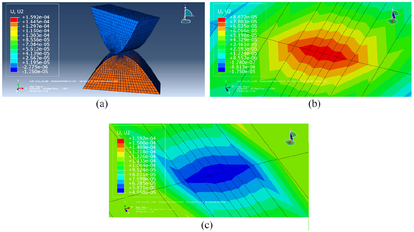
Deformation cloud: (a) global deformation, (b) local deformation of upper contact surface, and (c) local deformation of lower contact surface.
Contact deformation comparison
As shown in Figure 4, the simulation value solution of contact deformation is compared with the theoretical solution, in which the change of contact deformation with load under different contact angles is compared. Figure 4 indicates that the contact deformation increases with the increase of load, exponentially in the elastic deformation and linearly in the plastic deformation.

Deformation comparison: (a) 45° contact, (b) 60° contact, and (c) 90° contact.
In order to further compare the error between the simulation solution and the simulation solution of the contact deformation, the errors between the simulation solution and the simulation solution under the load of 0.06 KN and 0.16 KN are calculated in Table 1. And the error variation range is 9.00%∼5.81%. It can also be seen from Table 1 that with the increase of angle, the contact deformation increases.
Comparison of contact deformation.

There are two reasons for the error between the theoretical solution and the simulation solution of contact deformation. The first reason is that when the contact model is loaded to a certain value, the contact model will reach elastoplastic deformation. If the contact model is considered to be in the stage of elasticity or plasticity at this time, the contact deformation will be larger or smaller. The second reason is that there will be errors in the establishment and analysis of contact model, which mainly include mesh size and type, analysis methods, setting of constraints and loads, and model simplification.
Contact analysis
Load influence on contact stiffness
Figure 5 shows load influence on contact stiffness. The model parameters are as follows: A = 0.5 mm, f = 2 mm, E = 2.1 × 10⁵ MPa, u = 0.3, σs = 350 MPa. Figure 5 shows that with increasing loads, the contact stiffness increases in the elastic stage. And the load has no effect on the contact stiffness in the plastic stage. It can also be seen that with the increase of the contact angle, the contact stiffness decreases.

Load influence on contact stiffness.
Load influence on contact area
The effect of load on area is shown in Figure 6. The model parameters are as follows: A = 0.5 mm, f = 2 mm, E = 2.1 × 10⁵ MPa, u = 0.3, σs = 350 MPa. Figure 6 indicates that with the increase of load, the contact area increases in the elastic deformation, which is growing exponentially. And with the angle increases, the area decreases. As the increase of load, the area increases linearly in plastic deformation, which is not affected by the contact angle.

Load influence on contact area.
Amplitude influence
Figures 7 to 9 indicate the effect of cosine wave frequency. The model parameters are as follows: f = 2 mm, E = 2.1 × 10⁵ MPa, u = 0.3, σs = 350 MPa, load in elastic stage P1 = 0.05 KN, load in elastic stage P2 = 0.1 KN. It can be seen from Figure 7 that with the increase of amplitude, the contact deformation increases, which is exponential in the elastic deformation and linear in the plastic deformation. Figure 8 shows that as the increase of amplitude, the stiffness decreases and gradually become zero. Figure 9 indicates that with the decrease of amplitude, the area increases in elastic stage. And the amplitude has no influence on the area in the plastic stage.

Amplitude influence on deformation.
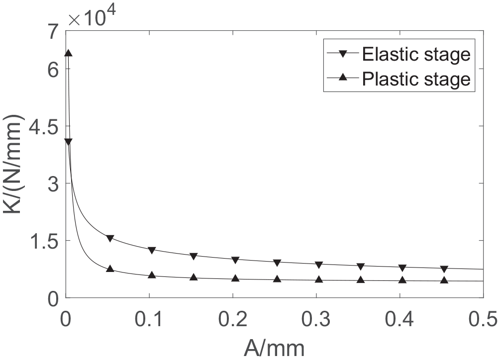
Amplitude influence on stiffness.

Amplitude influence on area.
Wavelength influence
Figures 10 to 12 show the effects of cosine wave wavelength. The model parameters are as follows: A = 0.5 mm, E = 2.1 × 10⁵ MPa, u = 0.3, σs = 350 MPa, load in elastic stage P1 = 0.05 KN, load in elastic stage P2 = 0.35 KN. Figure 8 shows that with increasing wavelength, the contact area decreases. As shown in Figure 9, as the increase of the wavelength, the stiffness decreases and gradually become infinite at the plastic stage. As can be seen from Figure 10, with the increase of the wavelength, the contact area increases in the elastic stage. And the wavelength has no influence on the area in the plastic stage.

Wavelength influence on deformation.

Wavelength influence on stiffness.

Wavelength influence on area.
Conclusion
An elastic-plastic contact mechanics model of cosine wave under different axial contact angles is proposed.
According to the established model, the relationship between contact angle, load and contact deformation, contact stiffness and contact area is studied and verified by finite element method.
Based on the two cosine wave elastic-plastic contact model, the mechanical characteristics of the regular joint surface like cosine wave in precision machining can be further studied, which provides a theoretical basis for the calculation of the contact stiffness of the regular joint surface.
Footnotes
Appendix
Declaration of conflicting interests
The author(s) declared no potential conflicts of interest with respect to the research, authorship, and/or publication of this article.
Funding
The author(s) disclosed receipt of the following financial support for the research, authorship, and/or publication of this article: NSFC (Grant No. 51875009).