
Abstract
Traditional hand-held ultrasound probe has some limitations in prostate biopsy. Improving the localization and accuracy of ultrasound probe will increase the detection rate of prostate cancer while biopsy techniques remain unchanged. This paper designs a manipulator for transrectal ultrasound probe, which assists doctors in performing prostate biopsy and improves the efficiency and accuracy of biopsy procedure. The ultrasound probe manipulator includes a position adjustment module that can lock four joints at the same time. It reduces operating time and improves the stability of the mechanism. We use the attitude adjustment module designed by double parallelogram RCM mechanism, the ultrasound probe can realize centering and prevent its radial motion. The self-weight balance design helps doctors operate ultrasound probe without weight. Using MATLAB to analyze the manipulator, the results show that the workspace of the mechanism can meet the biopsy requirements. And simulate the centering effect of the ultrasound probe when the attitude is adjusted at different feeding distances, the results show that the ultrasound probe is centering stability. Finally, the centering and joint interlocking tests of the physical prototype are completed. In this paper, a 7-DOF manipulator for transrectal ultrasound probe is designed. The mechanism is analyzed for kinematics, workspace analysis, simulation of centering effects, development of a physical prototype and related experimental research. The results show that the surgical demand workspace is located inside the reachable workspace of the mechanism and the joint locking of the manipulator is reliable.
Introduction
Transrectal prostate biopsy is the gold standard for the diagnosis of prostate cancer. 1 Currently, the commonly method used in prostate biopsy is to perform a biopsy of the prostate through the rectum under the guidance of ultrasound images,2,3 the ultrasound probe is equipped with a needle guide for transrectal access to the prostate (see Figure 1). However, there are still some problems in the biopsy procedure. During the biopsy targeting process, even experienced urologist can’t accurately dissect the target tissues in the expected biopsy procedure. 4 It is also difficult for doctors to perform repeated sampling on the same target. The ultrasound probe is inserted into the patient’s rectum during the biopsy, there is radial motion causing damage to the rectum when adjusting the probe attitude. Related study demonstrated that the use of robotic-assisted ultrasound probe for biopsy can significantly reduce repeated biopsy errors, improve precision and accuracy and increase the average significant prostate cancer detection rate. 5 Robotic prostate biopsy is an emerging technology, Miah et al. reported on of the largest series of men who underwent robotically assisted prostate biopsy. The results have demonstrated a high detection of clinically significant prostate cancer when combined with only limited near-field sampling, shorten the learning curve and added technological security. 6 Schneider et al. designed a 3-DOF motorized reobotic probe, which can provide accurate needle placement and greatly reducing contact with the muscles and nerves. The device is mounted to the ultrasound device, resulting in accurate registration of the needle end-effector with respect to the ultrasound image. 7 Phee et al. designed a percutaneous biopsy of the prostate robot system. Combined with the three-dimensional image reconstruction, the doctor determines the prostate puncture point and the perineal entry point based on experience. The robot system can automatically calculate the optimal needle path and perform three-dimensional simulation before the needle is inserted. The doctor manually operates the biopsy device to obtain the lesion tissue. 8 Yu et al. developed a robotic system with 16 degrees of freedom (DOF) (9 DOF for the positioning module and 7 DOF for the surgery module) for prostate brachytherapy. The system can obtain ultrasound images of the lesion area by rotating operation in an automatic or manual manner.9,10 The experimental results show that the system has achieved good therapeutic effects. Fichtinger et al. developed a robotic system that includes ultrasound image navigation and treatment planning system (TPS). The most important feature of the system is that a small 4 degrees of freedom (DOF) parallel robot is installed directly above the ultrasound probe, so that the coordinate system of the parallel robot and the ultrasound probe adjustment mechanism is the same, ensuring that the system’s workflow and calibration standards have not changed. 11 Stoianovici Dan et al. designed a robotic device for holding and manipulating the ultrasound probe for intraoperative ultrasound image navigation. The TRUS robot has 4 DOFs and is controlled remotely by the surgeon. Robotic-assisted prostate biopsy can reduce prostate motion and deformation errors.12–14 Virtrami et al. designed a manipulator for assisting endorectal prostate biopsy, possessed 6 DOFs. The manipulator has a free mode and a locked mode. Besides, the urologist can switch them at will. Clinical trials were performed with or without the assistance of manipulator. The main purpose was to compare the accuracy of biopsy. The results show that the use of manipulator has a statistically significant increase in biopsy accuracy.15,16 Although active prostate interventional robots have been extensively studied, due to their complex systems and high cost, it takes longer to obtain medical device license certification and longer training time for use. It is more difficult to promote and apply while passive platforms with auxiliary and support functions are also the same. It can meet the requirements of biopsy procedure, so it is necessary to study the passive ultrasound probe manipulator of transrectal puncture.
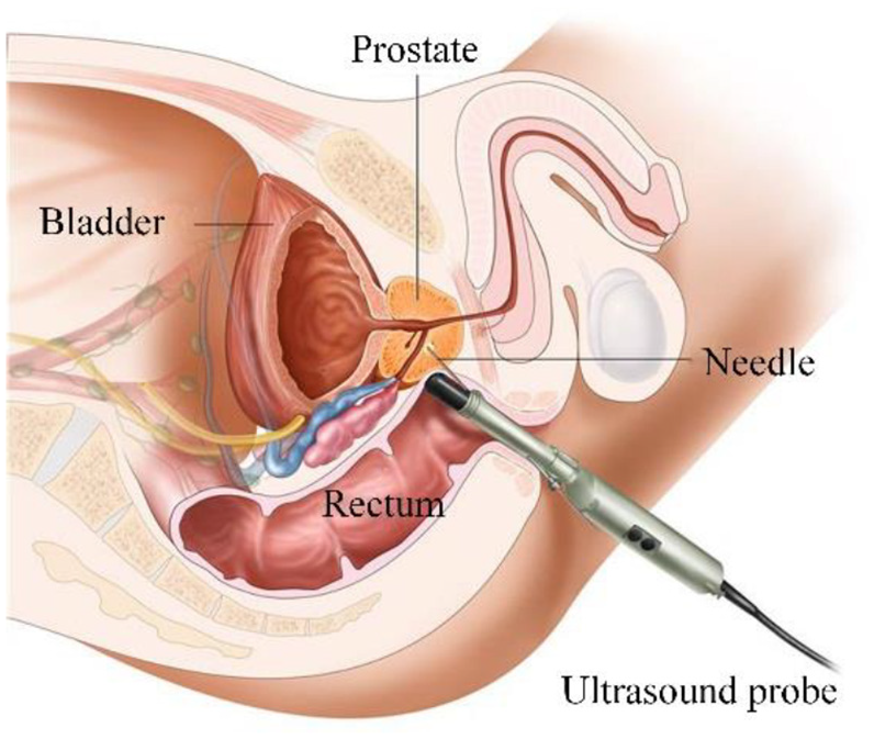
Transrectal biopsy of the prostate.
During the biopsy procedure, the ultrasound probe should always be operated with the center of the anus as the rotation center to avoid damage to the rectum and alleviate the pain of the patient. The key technology of the passive prostate assisted interventional device is the centering motion of the transrectal ultrasound probe, and the use of a remote center of motion (RCM) mechanism can achieve the centering motion of the ultrasound probe, thereby liberating the doctor’s hands. Various RCM mechanisms are widely used in robotic-assisted minimally invasive surgery (MIS). There are eight types of RCM mechanisms used for MIS robots, such as isocenters, cicular tracking arcs, parallelograms, synchronous belt transmission, spherical linkages, parallel manipulators, compliant mechanisms and passive RCMs. 17 And the double parallelogram mechanism is most widely used RCM mechanism in MIS robots. 18 Taylor et al. first proposed the concept of “remote-center-of-motion robot” and designed a laparoscopic surgical robot, which consists of a 3-axis linear xyz stage and a 2-axis four-link parallel mechanism providing two rotations. The yaw rotation center and the pitch rotation center of the mechanism intersect at the remote motion center. The posture of the puncture needle can be adjusted arbitrarily in these 2-axis, the position of remote motion center can be adjusted by the expansion of the connecting rod. 19 Planar RCM mechanisms like the double parallelogram mechanism only provide 1 DOF, Li et al. proposed an RCM mechanism type synthesis method based on the intersecting motion planes. By constructing several planar mechanisms with movable planes whose common intersecting line passes through a fix point.20,21 Nisar et al. presents a new RCM mechanism which provides 2 DOFs, including roll and translation DOF, the novelty of the design is that it provides a significantly smaller footprint than the existing 2-DOF plan.22,23 Although the current RCM mechanisms designed by research scholars can meet the requirements of surgery, they all have the problems of complex structure, poor stability, and large space occupation.
In order to solve these problems, this paper analyzes the actual working space and functional requirements of transrectal prostate biopsy. Based on the integration of the current prostate intervention robot system and the remote end adjustment mechanism, a novel 2-DOF RCM mechanism is designed based on the double parallelogram mechanism for ultrasound probe yaw DOF and pitch DOF, so that operate the ultrasound probe to move around a fixed point. In order to ensure the safety of the biopsy and improve the positioning accuracy, reliable locking is required when the ultrasound probe is at any pose in space. Based on this, this paper designs a 7-DOF manipulator for transrectal ultrasound probe, which can realize continuous motion around the centering point, provide reliable joint interlocking, adopt gravity self-balancing design and assist the doctor to operate the ultrasound probe without weight to complete the biopsy procedure.
7-DOF Manipulator structure design
Analysis of the operable space of mechanism
During the transrectal prostate biopsy procedure, in order to reduce the patient’s pain, the left lying position is adopted, as shown in Figure 2. The back of the body is 30–45° from the edge of the operating table, the thigh is 45–60° from the edge of the bed, the distance of the prostate from the bed surface is 150–250 mm. The left lying position can well expose the anus, which provides convenience for the ultrasound probe into the rectum.
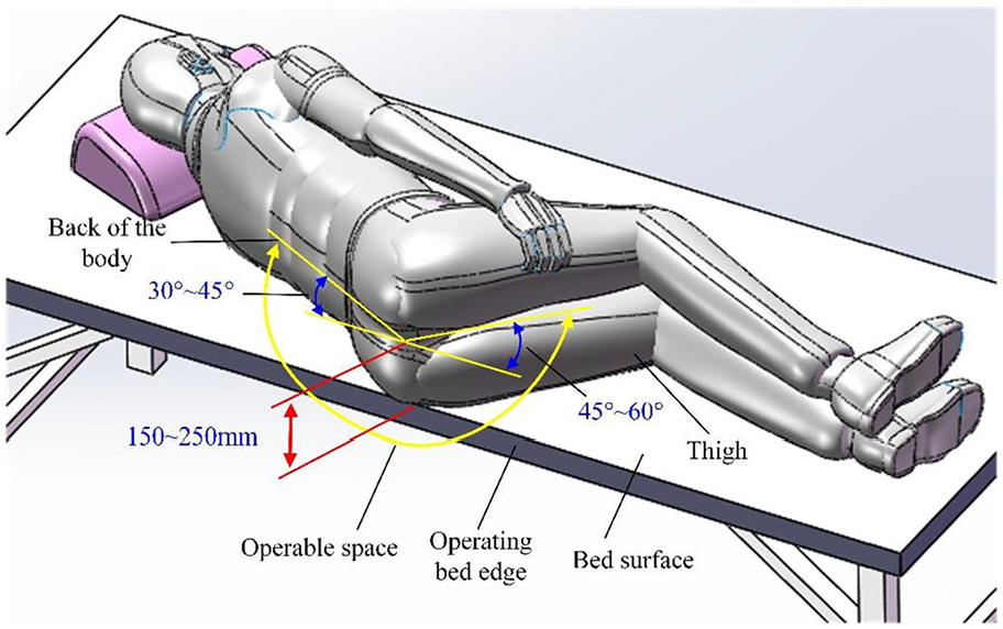
Operable space of mechanism.
Transmission scheme
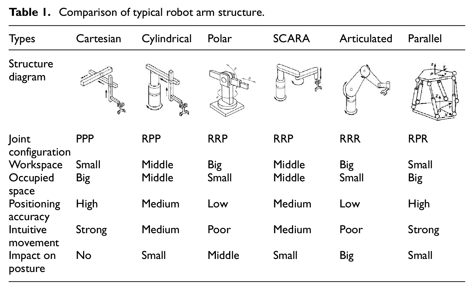
In view of the particularity of the passive transrectal ultrasound probe manipulator, it is necessary to design a suitable configuration so that it can realize the position and attitude adjustment, rotation and feed adjustment of the ultrasound probe. The first is to analyze the configuration of the position adjustment module. After summary, there are currently six types of robot arm configurations: cartesian, cylindrical, polar, articulated, SCARA, parallel robot, 24 This paper compares various structure types of the manipulator from several indicators such as workspace, occupied space, positioning accuracy, intuitiveness of movement, and the effect of joint motion on the end-effector posture. The specific analysis and comparison are as show in Tables 1 and 2. 25
Comparison of typical robot arm structure.
The advantages and disadvantages of various types of robot arm.

From the above analysis, it can be seen that the SCARA robot has a light structure, small size, light weight, large working space, high positioning accuracy, strong intuitive movement and meets the requirements of surgical operation instruments. At present, medical robots are also used SCARA type structure, the work is more reliable. The articulated robot has compact structure, small space occupation, and high flexibility. Therefore, the configuration of the position adjustment module designed based on the advantages of the SCARA robot and the articulated robot is shown in Figure 3. The module has 3 DOFs, and four rotary joints. The joint link of the joint 2 and the joint 3 adopts a parallelogram mechanism composed of two links, so as to ensure that the end coordinate system only moves along the X axis, Y axis, and Z axis.

Structure diagram of 7-DOF manipulator.
For the attitude adjustment mechanism, choose a 2-DOF structure. In order to enable the ultrasound probe to achieve centering motion around the center point of the anus during the biopsy procedure, the configuration of the attitude adjustment adopts an RCM mechanism. At present, there are two main ways to achieve telecentric positioning: one is to achieve telecentric motion through multi-joint coupling, but this method is mainly realized by an algorithm, which requires high stability and reliability of the algorithm. Moreover, the safety is poor, the other is through mechanism constraints. 26 Because of the high safety of this method, it is widely used in the research of minimally invasive medical robots. 27 There are four main ways to restrain the attitude mechanism: spherical mechanism, double-arc slide rail mechanism, single-arc slide rail mechanism and telecentric parallelogram mechanism. The comparative analysis is shown in Table 3. Because the attitude adjustment module is located at the end of the position adjustment module, the RCM mechanism must be as lightweight as possible to reduce the load. After comprehensive consideration, the dual parallelogram mechanism was selected for the attitude adjustment module.
Comparison of remote center of motion.

The mechanical structure of the 7-DOF manipulator mainly includes a 3-DOF position adjustment module, a 2-DOF attitude adjustment module, a 2-DOF rotation and feed module of ultrasound probe (see Figure 3). The design scheme can complete the basic functions of operating the ultrasound probe and make the mechanism flexible enough. The motion relationship between the three modules is completely decoupled and does not interfere with each other, which reduces the complexity and design difficulty of the mechanism.
Attitude adjustment module design
The attitude adjustment module adopts an RCM mechanism based on a double parallelogram. In order to facilitate the description of the characteristics of the mechanism, the schematic diagram is shown in Figure 4, the double parallelogram is parallelogram ADCF and parallelogram BCIJ. In order to conveniently describe the characteristics of the mechanism, the local coordinate system is established in Figure 4. When the link DF swings α angle with point D as the center, the double parallelogram mechanism has the following characteristics:
Parallel characteristics, AD // BI // CJ, AC // DF // IJ;
Centering characteristics, the position of the intersection point H of the AD extension line and the JI extension line is always unchanged.
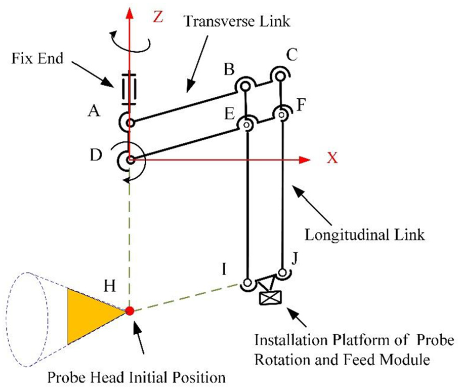
Schematic diagram of attitude adjustment module.
When the doctor performs the biopsy procedure, the interserction point H is at the center point of anus (see Figure 5). In order to prevent the attitude adjustment module from interfering with the patient’s body, according to the size of the human body,


Analysis of swing angle of ultrasound probe.
In order for the ultrasound probe to cover the entire area of the prostate, β and γ should satisfy the following equation:


then

Rotation and feed module design
The mounting block is connected to the attitude adjustment module, and two parallelly placed polished rod are slid in the mounting block for achieving the feed freedom of the ultrasound probe along the center of the anus. The fixed ring is mounted on the polished rod, and the rotating cylinder is nested in the fixed ring. The rotating ring is mounted on the other end of the rotating cylinder to restrict the axial movement of the rotating cylinder in the fixed ring (see Figure 6). The side of the fixed ring defines a circular groove with a central angle of 90°, and a limit pin is mounted on the rotating ring. And sliding in the circular groove can limit the rotation angle of the rotating cylinder in the fixed cylinder, which realizes the rotation DOF of the ultrasound probe (see Figure 7). In this design, six hand-screws are used to mount the two ends of the rotating cylinder. A rubber clamping block is mounted on each of the hand-screws. The ultrasound probe can be clamped or loosened by manually adjusting the position of each of the hand-screws.

Rotation and feed module of ultrasound probe structure diagram.

Rotation and feed module of ultrasound probe structure diagram.
Joint interlocking mechanism design
The joint 5 and the joint 6 of the attitude adjustment module are rotating joints for setting the scanning posture of the ultrasound probe relative to the prostate. Once the ultrasound probe reaches the required posture, the joint is locked to meet the operational precision of the terminal device. Because the attitude adjustment module needs to be frequently locked or moved during the biopsy procedure, it is necessary to ensure the operational flexibility and the convenience of locking. The electromagnetic power off brake can be selected as the locking part of the joint, the above requirements are well met (see Figure 8). When the electromagnetic brake is powered off and then the brake is engaged, the ultrasound probe can stably maintain a given posture. However, when the electromagnetic brake is disengaged, the ultrasound probe and the attitude adjustment module will naturally fall due to their own weight, so doctors need more force to operate the ultrasound probe, which is easy to cause operational fatigue. In this way, the gravity self-balancing design is adopted. Add a spring to the linkage to balance the heavy moment caused by its own weight (see Figure 9). When the transverse link is in the horizontal position and the feed distance of the ultrasound probe is 0 mm, the gravity moment generated by the attitude adjustment module on the pitch axis is the largest. For the convenience of calculation, the total gravity moment is decomposed into three component moments for solution, as shown in Figure 10. Using the mass properties in the SolidWorks software, the mass of the two transverse links is

Structure of yaw and pitch rotation joint.

Improved mechanism of system.
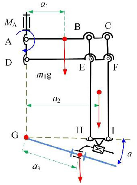
Total gravity moment of pitch axis.
The total gravity moment of the attitude adjustment module is:

The position adjustment module has a total of four joints. If each joint is locked separately, it will not only increase the weight of the module, but also occupy the doctor’s operating mechanism time. The designed joint interlocking mechanism solves this problem by separating the structures of the joint 1 and the joint 3 into upper and lower parts, as shown in Figure 11. The joint 1 connected to the upper arm in the upper half continues to separate into two parts, as shown in Figure 12. When a pair of forces F of equal size and opposite directions are applied to the A-side and B-side of the joint 1, the joint 1 can clamp both the post and the connecting rod due to the compression, thereby limiting the θ1 and θ2. When a parallelogram link is used to transmit the force F to the A-side and B-side of the joint 4, the joint 4 can clamp the connecting rod and the rotating shaft mounted on the arm, thereby limiting the angle of θ3 and θ4. The applied force F is generated by the hand-tightening bolts installed from the A-side of the joint 1 and the nuts fixed to the B-side of the joint 1. The interlock mechanism not only realizes the simultaneous locking of the four joints in the position adjustment module, simplifies the doctor’s operation, but also has a simple structure, low cost, and light weight.

Interlocking mechanism diagram.

Improved structure of joint 1.
Workspace analysis and prototype experimental study
Workspace analysis
The manipulator needs to have a large working space, high precision, and flexible pose during the biopsy procedure. Therefore, it is necessary to analyze the motion analysis and attitude adjustment of the manipulator. It is also an intuitive factor that reflects the performance of the manipulator. The doctor operates an ultrasound probe to reach the remote motion center of the mechanism to the center point of the patient’s anus. Because the attitude adjustment module dose not affect the position of the remote motion center, the set of point that the remote motion center can reach is the motion space of the mechanism. The connection between the end point of the scanning portion of the ultrasound probe and the end point of the hand-held part can express the motion posture of the ultrasound probe.
According to the motion range of each joint of the position adjustment module to set the simulation parameters as shown in Table 4. As can be seen from the Figure 13, the red area represents the range of the position of the central point of the anal periphery when patients of different sizes lie on the operating bed. And the blue area represents the range of movement of the remote motion center when the ultrasound probe position adjustment mechanism adjusts the position. The range of motion of the telecentric point completely covers the position range of the central point, so the mechanism can well meet the needs of patients of different sizes for position adjustment.
Position adjustment simulation parameters.


Workspace of remote center point: (a) three-dimensional workspace maps, (b) XOZ plane projection, (c) XOY plane projection, and (d) YOZ plane projection.
The attitude adjustment module enables the ultrasound probe to perform a centering function of swinging around a certain point and simulates the centering effect of the ultrasound probe. The motion parameters are shown in Table 5. When the feed distance
Attitude simulation parameters of ultrasound probe.

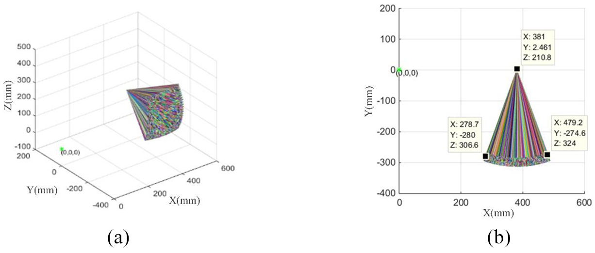
Attitude of ultrasound probe at 0 mm feeding, these lines to represent the center line of the probe with randomly given colors: (a) three-dimensional plots (
In order to observe the changes of the attitude of the ultrasound probe with different feeds, keep the joint parameters of the position adjustment module and the attitude adjustment module unchanged and only change the feed distance of the ultrasound probe to
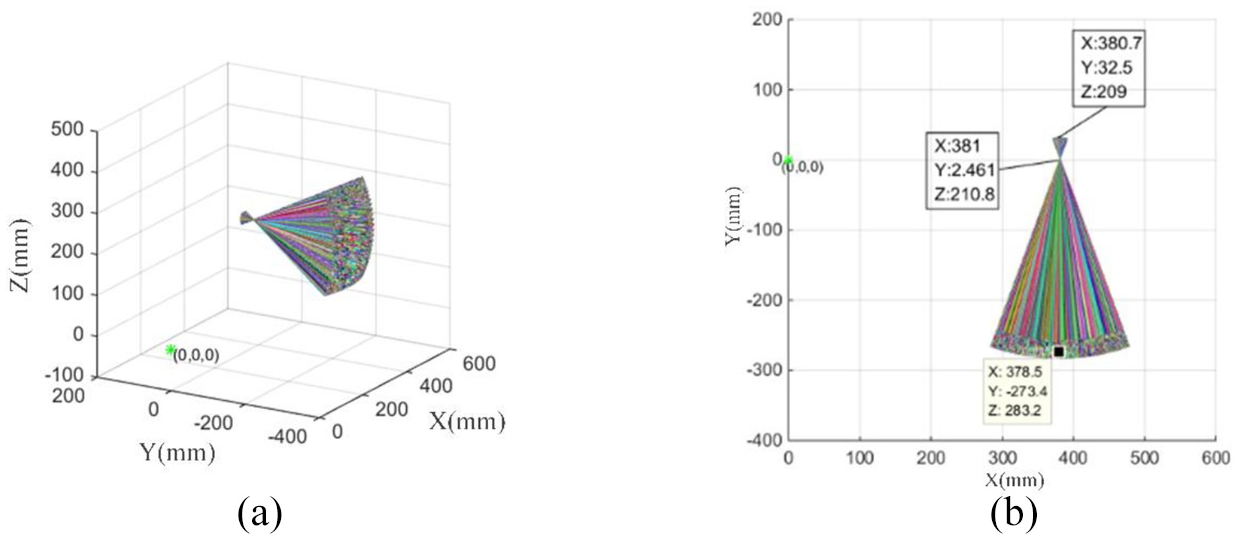
Attitude of ultrasound probe at 30 mm feeding: (a) three-dimensional plots (

Attitude of ultrasound probe at 60 mm feeding: (a) three-dimensional plots (
Manipulator for prostate biopsy experiment
Before the biopsy, the position adjustment module is dragged by the doctor to achieve the positioning of the mechanism in the vertical and horizontal directions. When the end of the ultrasound probe reaches the center point of the patient’s anus, the position adjustment module is locked to ensure the positioning accuracy (see Figure 17). According to the clinical requirements, the rotation angle
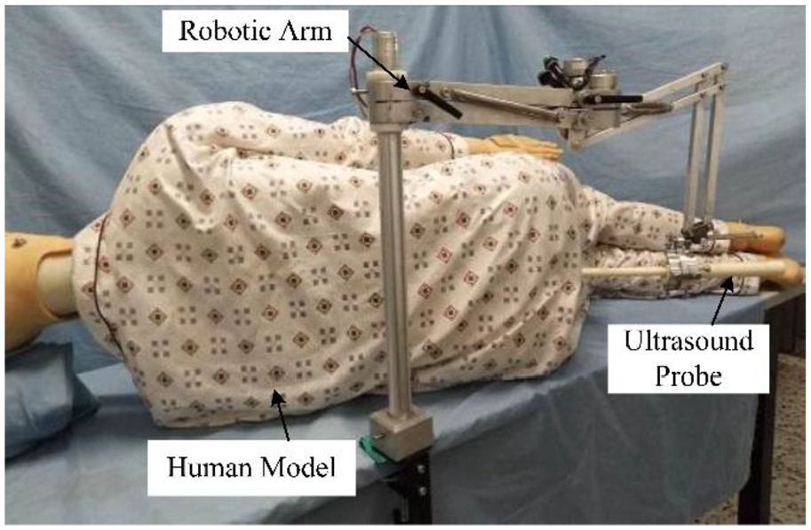
Physical prototype of manipulator.
Angle measurement of each joint in position adjustment module.
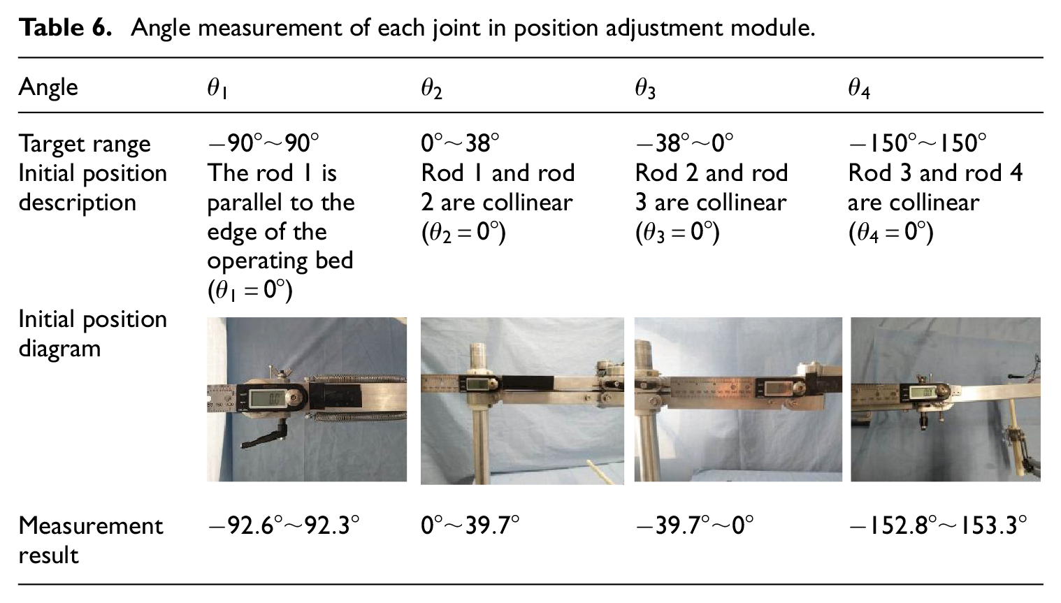
The experimental results of joint angle measurement show that each joint of the position adjustment module can continuously rotate and reach the required angle range, which satisfies the design requirements.
The distribution of the prostate position relative to the base coordinate system in different somatotype patients from 240 mm to 400 mm in X direction, from 0 mm to 120 mm in Y direction, from 150 mm to 250 mm in Z direction. This area is the surgical demand working space that the remote center point of the mechanism must reach. The shape is a rectangular parallelepiped with eight vertices. Adjust the end of the ultrasound probe to the remote center point of the mechanism, then lock the attitude adjustment module. Adjust the position adjustment module to test the ability of the mechanism to meet the requirements of the surgical workspace, as shown in Figure 18.

Workspace accessibility measurement: (a) x = 240, y = 0, z = 150, (b) x = 400, y = 0, z = 150, (c) x = 400, y = 0, z = 250, (d) x = 240, y = 0, z = 250, (e) x = 240, y = 120, z = 150, (f) x = 400, y = 120, z = 150, (g) x = 240, y = 120, z = 250, (h) x = 400, y = 120, z = 250, and (i) x = 320, y = 80, z = 200.
After testing, the mechanism can successfully reach the eight vertices at the boundary of the surgical workspace and any positions in the interior to meet the surgical requirements.
Mechanism error analysis
The motion characteristics of the RCM mechanism is the range of the remote motion center in the space when the ultrasound probe performs the attitude adjustment. Under the existing experimental conditions, the motion performance of the RCM mechanism can be evaluated by measuring the error between the spatial fixed point and the remote motion center. Because the positional change of the remote motion center in space is three-dimensional, and a fixed point in space can only measure the error of the RCM mechanism in the two-dimensional plane, two sets of experiments are needed. When the yaw or pitch angle is changed separately, the resulting errors are measured separately, as shown in Figures 19 and 20.

Measurement of yaw remote center point error.
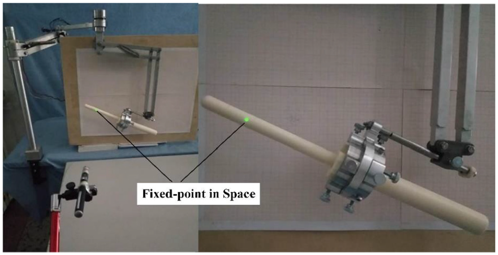
Measurement of pitch remote center point error.
Experimental variables: adjust the yaw angle
The experimental data obtained by multiple measurements is shown in Figure 21. The marked points on the coordinate paper are processed and measured, the distance from the remote motion center to the fixed point of the space is within 4 mm. The anal canal of human is 2.5–5 cm in length and 3 cm in diameter when distended, 30 and the diameter of the ultrasound probe (Endocavity 3D 8838, BK Ultrasound) for biopsy is about 16 mm. Therefore, the error of the remote motion center is within an acceptable range, and will not cause harm and discomfort to the patient. According to the results of the two sets of experiments, when the ultrasound probe adjusts the yaw and pitch angles under different feed rates, the positional change of the remote motion center in the space is within the deformation range of the anus, which has high precision that can meet the surgical requirements.

Remote center point error under different feed rates: (a) remote center point error under the motion of yaw angle and (b) remote center point error under the motion of pitch angle.
Conclusion
In this paper, a manipulator for transrectal ultrasound probe is designed, which includes a position adjustment module that can simultaneously lock four joints. Furthermore, it can improve he stability of the surgeon’s gesture. The attitude adjustment module designed by the double parallelogram RCM mechanism enables the ultrasound probe to achieve the centering function in order to prevent its radial motion. The rotation and feed module of ultrasound probe is designed for easy installation of puncture probe and can clamp the irregular shape ultrasound probe. Weight self-balancing design is used to help doctors to operate ultrasound probe without weight.
Through the workspace analysis of the mechanism, the surgical demand workspace is located inside the reachable workspace of the mechanism, which can meet the surgical requirements. When the attitude is adjusted under different feed distances, the centering effect of the ultrasound probe is simulated. The results show that the centering effect of the ultrasound probe is stable, thus verifying the position and attitude adjustment module of the ultrasound probe meet the design requirements.
The physical prototype of the manipulator is developed and tested. It is proved that the mechanism can flexibly reach any position in working space of the prostate biopsy and locking is reliable. The centering effect of the remote motion center when adjusting the attitude of the ultrasound probe is measured, and the displacement range of remote motion center in the space is within 4 mm. The results show that the centering accuracy of the ultrasound probe when adjusting the attitude under different feed rate meet the surgical requirements.
Footnotes
Declaration of conflicting interests
The author(s) declared no potential conflicts of interest with respect to the research, authorship, and/or publication of this article.
Funding
The author(s) disclosed receipt of the following financial support for the research, authorship, and/or publication of this article: This work was supported by the National Natural Science Foundation of China (Grant No. 51675142) and by the Natural Science Foundation of Heilongjiang Province of China (Grant No. ZD2018013).