
Abstract
To meet various industrial requirements such as ease of motion, scalability, and cost efficiency, it is necessary to innovate the design of robotic platforms. In this research, a novel approach, from mechanical design to control implementation, is introduced for launching a robotic platform using a parallelogram mechanism. First, a reverse engineering process is applied, progressing from kinematics to dynamics. Then, several mechanical computations are conducted to ensure the structural stability of the robot framework. Subsequently, the dynamic performance of the system is analyzed, focusing on the driving torque and moments in each link. Additionally, the electrical design and transfer function of each joint are identified to ensure practical execution. To validate the effectiveness and feasibility of the design, both numerical simulations and experimental tests are performed. Theoretical results show the dynamic response of the proposed method, particularly in terms of the driving moments of the robotic joints. In real-world tests, various trajectories, such as different rectangular paths, are demonstrated to showcase the robot's capabilities. From these results, it is clear that the proposed approach is both feasible and applicable in practical scenarios.
Introduction
Robotic manipulators have transformed numerous industries by offering precision, efficiency, and versatility across a wide range of tasks.1–3 Among the various mechanisms employed in robotic arm designs, the parallelogram mechanism stands out as an ingenious and highly efficient solution. This mechanism plays a crucial role in enhancing the dexterity and agility of robotic manipulators, making them indispensable in fields such as manufacturing, 4 automation, 5 healthcare, 6 entertainment, 7 the beverage industry, 8 and beyond.
The parallelogram mechanism, also known as a parallel linkage or parallel arm, is a mechanical configuration that consists of interconnected links and joints arranged to replicate the geometry of a parallelogram.9–11 This setup enables the robotic arm to maintain a constant orientation of its end-effector, or tool while manipulating objects. Its inherent stability and precision make it an ideal choice for tasks requiring high accuracy and consistency.
Typically, the term such as parallelogram mechanism refers to a specific type of mechanism used in robotic manipulation and various engineering applications. It is a four-bar linkage that maintains parallelism between two sides of the mechanism as it moves. The most common application of parallelogram mechanisms is to provide stable and parallel motion for end-effectors or tools in robotics.12,13 Various types and configurations of parallelogram mechanisms exist, each with distinct advantages and applications. Recently, efforts have been made to develop reconfigured versions suitable for robots operating on diverse terrains.14,15 The contributions of our work are to (i) indicate the theoretical computations of both forward kinematic and inverse kinematic, physical dimensions and displacement validation in mechanical design, (ii) derive the dynamical analysis of the proposed platform to obtain the tracking performance, and (iii) conduct the experimental platform for laboratory robot in several validations.
Related works
A parallelogram mechanism is a mechanical linkage system composed of four rigid members connected to form a closed loop with two pairs of parallel sides. This mechanism is widely used in various engineering applications to create stable, predictable motion or to maintain a consistent orientation of an object. The internal structure of a parallelogram mechanism typically includes the following components: four rigid links, joints or hinges, an actuator, a support structure, a control system, bearings and bushings, linkage design elements, and safety features.16,17
Four rigid links: The core of the parallelogram mechanism consists of four rigid links or bars. These links are connected at their endpoints to form the closed loop. Two pairs of opposing links are parallel to each other, and their relative lengths and angles determine the behavior of the mechanism. Joints or hinges: At the endpoints of each rigid link, there are hinge or joint connections. These joints allow the links to pivot or rotate relative to each other, enabling the mechanism to change shape and adapt to different positions or orientations. Actuators: Parallelogram mechanisms may include actuators such as motors or pistons that are connected to one or more of the links. These actuators provide the necessary force or motion to drive the mechanism and control its movement. The actuators can be positioned at various points in the mechanism, depending on the specific application. Support structure: In many applications, the parallelogram mechanism is mounted on a support structure or base. This base provides stability and often serves as a reference point for the mechanism's operation. Control system: Depending on the complexity of the application, a control system may be integrated into the mechanism. This system can include sensors, feedback loops, and controllers to monitor and regulate the motion of the mechanism, ensuring that it operates accurately and precisely. Bearings and bushings: Bearings and bushings are often used at the joint connections to reduce friction and allow for smooth rotation of the links. These components help improve the efficiency and longevity of the mechanism. Linkage design: The lengths and angles of the four links are carefully designed to achieve specific types of motion or maintain a particular orientation. The precise design depends on the intended function of the mechanism, such as maintaining a parallel relationship between two objects or creating a specific path of motion. Safety features: In some applications, safety features such as limit switches, emergency stop mechanisms, or mechanical locks may be incorporated to ensure the safe operation of the parallelogram mechanism and prevent accidents.
The inside structure of a parallelogram mechanism can vary significantly depending on its intended purpose, size, and complexity. Engineers and designers carefully select and configure the components to meet the specific requirements of the application, whether it is for industrial automation, robotics, or any other field where controlled motion or orientation is essential (Table 1).
Summary of the state-of-the-art in related fields.

The proposed approach
In this approach, a reverse concept in robotic design is employed to explore advantageous features such as task-centric design, efficiency, and customization. First, both forward and inverse kinematics are applied to determine system parameters, such as the Denavit-Hartenberg (D-H) table. Then, theoretical errors are assessed to predict potential deviations in real-world applications. Second, the mechanical structure of the entire robot is completed to create a functional platform.
Forward kinematic
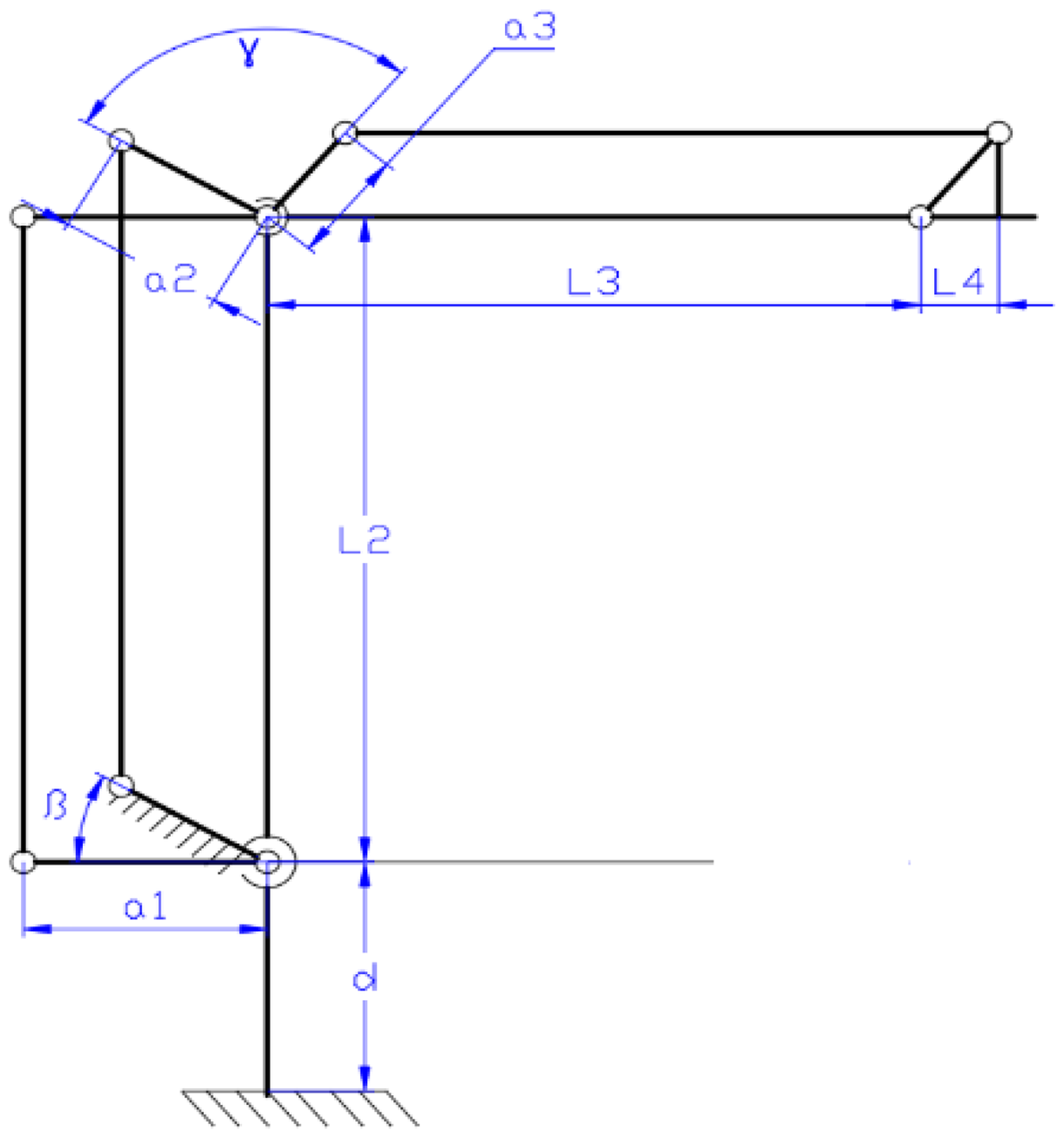
The structure of this robot is illustrated in Figure 1. Local coordinate systems are assigned to each link, and geometric parameters are introduced to evaluate the shape and length of the robot. These parameters are summarized in Table 2.

Demonstration of the geometrical parameters in the computation of forward kinematics.
List of Denavit-Hartenberg (D-H) parameters for the proposed design.

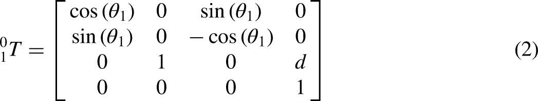
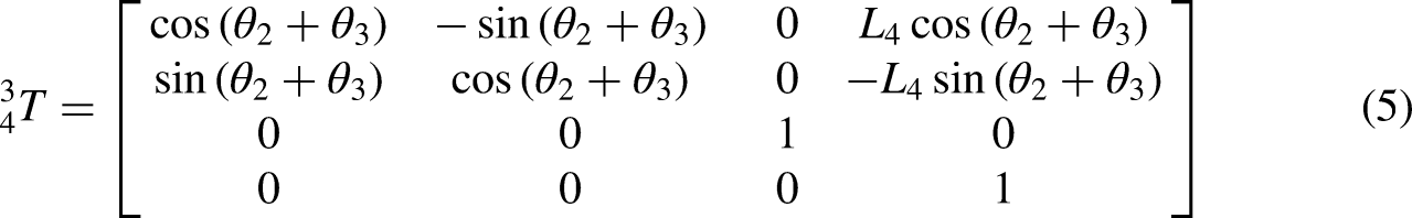
In general, matrix transformation from link i to i − 1 is


Therefore, the location of the end-effector is computed as follows: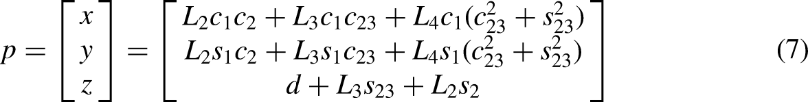


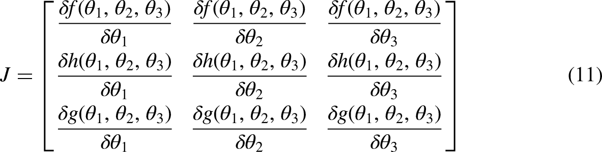

Note that the end-effector velocity is related to the joint velocities through an expression
We have a relationship between the end-effector acceleration of the robot and the joint acceleration velocities through a formula

Inverse kinematic
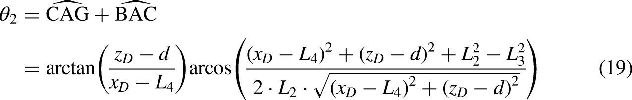
The meaning of the reverse kinematics problem is to determine the values of the variables that match the given position and orientation of the end-effector. In the context of the palletizing robot, it is responsible for maintaining the orientation of the end-effector. Thus, the computational process would not be overly complex compared to robots that have to control the orientation of the end-effector. The use of geometric methods as Figure 2 is employed to find the joint angles with the desired point D values.

Demonstration of the geometrical parameters in the computation of reversed kinematics.
We assume that the location of the desired point D is [


To evaluate the system error, with these inputs consisting of

Simulation of the system error in (a) x-axis, (b) y-axis, and (c) z-axis.
Mechanical design
In Figure 4, the working range of the robot arm is determined by two parameters, namely
Theoretical diagram for the design parameters of our robot.
With those design parameters, each mechanical component is analyzed as shown in Figure 5 using the ANSYS software tool. The working conditions of the proposed design should be validated by the displacements of robotic links. All links have a displacement of < 0.3 mm when operating at the maximum load as per the specified theory of the assignment. Henceforth, our selection of mechanical parameters ensures the durability of whole links.

Theoretical analysis of the displacement using ANSYS software for (a) link 1, (b) link 2, (c) link 3, (d) link 7, and (e) link 5.
The parameter values such as
List of the system parameters in the Denavit-Hartenberg (D-H) matrix.

Dynamical analysis
Based on the design from the previous sections, our goal is to determine the necessary forces to drive the manipulator. Since the driving motors for each link must be specified, more appropriate specifications are selected based on the results of this section. First, the dynamic equations relating to the existing forces and moments are identified. Then, relevant mathematical terms from these equations are computed. As a result, the required moments at links 1, 2, and 3 can be determined. In the analysis of dynamics, several commonly applied methods are used, including the Lagrange method,
23
Gauss method,
24
Kane method,
25
and Robertson-Weiden Fort method,
26
among others. In this study, the Newton-Euler method
27
is utilized. This method combines Newton's force equilibrium with Euler's moment balance to calculate the required torque for moving components at the desired velocity and acceleration. We have,


Typically, for open-loop or serial robots with conventional transmission systems, the system can be easily solved because each component experiences two forces. At the end-effector, there is only one force or load, as specified by the problem, resulting in a unique solution for the dynamic analysis. However, the core issue arises when the robot incorporates two parallel mechanisms. Some components, such as the ninth, seventh, and fifth, experience more than two forces and moments. To solve the dynamic analysis of a closed system, it is necessary to reduce the number of forces acting on these complex components.
According to the equations of motion, the system's dynamics depend solely on its motion. Therefore, if the Newton-Euler approach can reduce the excess forces while maintaining the overall motion of the robot, the results from the Newton-Euler and Lagrange methods would remain identical. Simplification or elimination of forces and moments occurs during the calculation process.
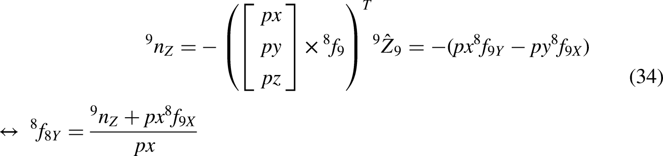
As shown in Figure 6, local coordinates are assigned to each link as follows: coordinate 1 is linked to link 1; coordinate 2 to links 2, 4, and 6; coordinate 3 to links 3, 5, and 8; and coordinate 4 to links 7 and 9. Next, we consider link 9 as described below:

Theoretical diagram of local coordinates for dynamic analysis.
To simplify, we proceed to classify the moment
The total force between two joints related to links 8 and 5 is


The relative force between links 9 and 8 has been solved


The total force between two joints related to links 2 and 6 is


Likewise, we reach 

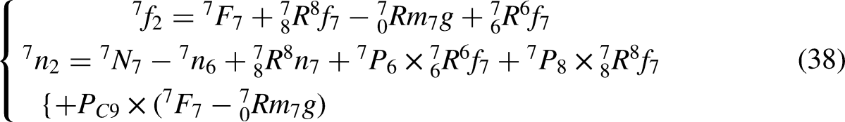
For link 7


The total force between two joints related to links 2 and 4 is


Later


Validation of research
Numerical simulation
The proposed model of our robot in 3D space is launched. In each link, a local coordinate is attached to indicate the orientation and dimension of the system parameters. It is assumed that the reference trajectory of the robot is a circular path with the center coordinates
From the inverse kinematics computation, the relationship between the end-effector's velocity and the angular velocities of the joints, as well as the relationship between the end-effector's acceleration and the joints’ angular accelerations, is established based on system (58) and the specified requirements. As a result, a sequence of joint angles, joint angular velocities, and joint angular accelerations is obtained, as shown in Figure 7. These reference trajectory values are then inserted into the dynamic equations to obtain the system's response. The entire system is simulated in the Matlab Simulink environment to verify its high performance, as depicted in Figure 8.

Simulation result of the circular reference path for the proposed approach, (a) angular position, (b) angular velocity, and (c) angular acceleration with green line for joint 1, red line for joint 2, and yellow line for joint 3.

Simulation setup of the dynamic equations in Matlab/Simulink for the proposed robot.
The robot's response, as shown in Figure 9, demonstrates that the driving moments in both the simulation and theoretical computation are consistent. Additionally, the dynamic constraints can be used to select the appropriate driving motor and assess the robot's durability.

Result of the driving moments in simulation (a) with blue line for joint 1, red line for joint 2, yellow line for joint 3, and in theoretical computation (b) with black line for joint 1, green line for joint 2, and pink line for joint 3.
Experimental validations
To operate this platform, the electrical design, as shown in Figure 10, must be implemented, including power sources and control signals. The system generally consists of four main blocks:
Motor block: Three DC (direct current) motors with positioning encoders, and a driver to interface between the microcontroller and the motors. Sensor block: Three proximity sensors are used to detect the HOME position. Control block: A CPU (central processing unit) responsible for receiving signals from the sensors and transmitting control signals to the motor drivers. Power block: Two primary power sources—a 24 V supply for sensors, drivers, and motors, and a 5 V supply for the microcontroller and positioning encoders.

Diagram of the electrical wiring system for our approach.
In the next step, the motor control scheme incorporates a proportional–integral–derivative controller. The transfer function of the driving motor is derived from the theoretical model as follows:

In the SI system, the torque constant and the electromotive force constant are equal, 


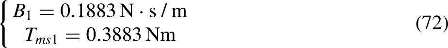
Usually, the value of L is much smaller compared to other motor parameters, so we can neglect L in the transfer function. We have the first-order transfer function of the motor as follows:
In theory, three parameters 
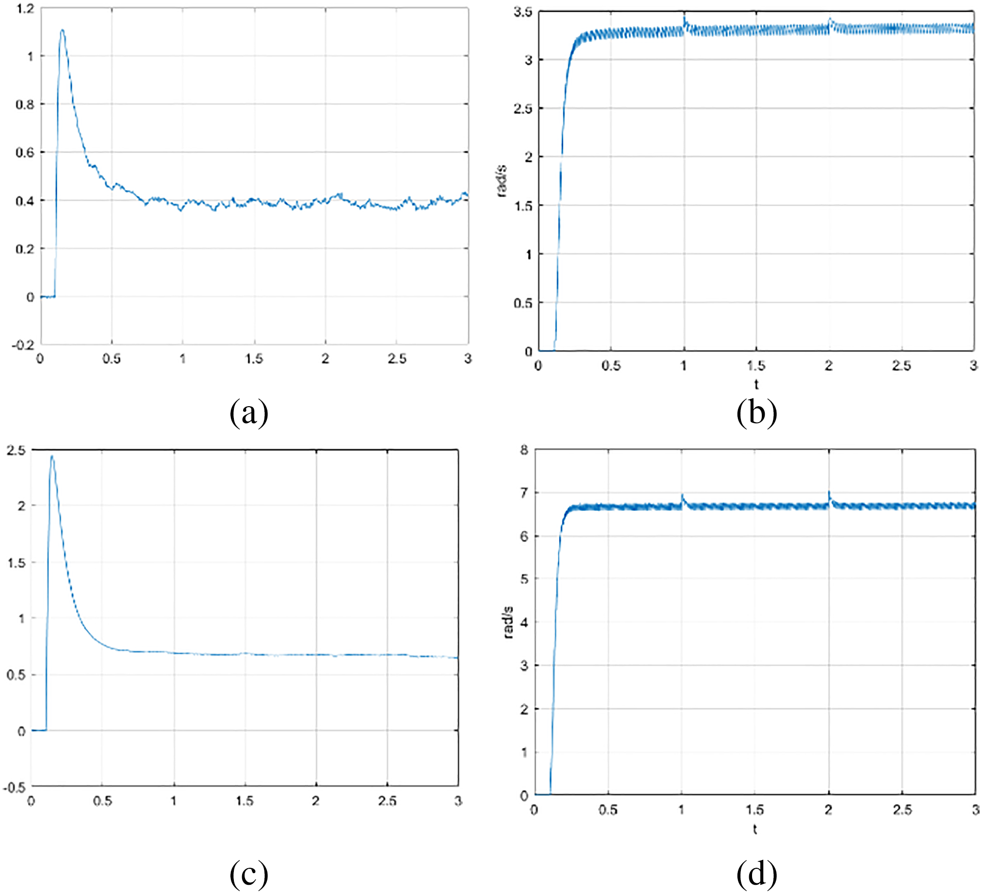
For the joint 1 with 12 V power, by measuring the average values of current and angular velocity as shown in Figure 11(a) and (b), we have Experimental response of the driving motor at joint 1 when the power supply is 12 V ((a) current and (b) angular velocity) and when the power supply is 24 V ((c) current and (d) angular velocity).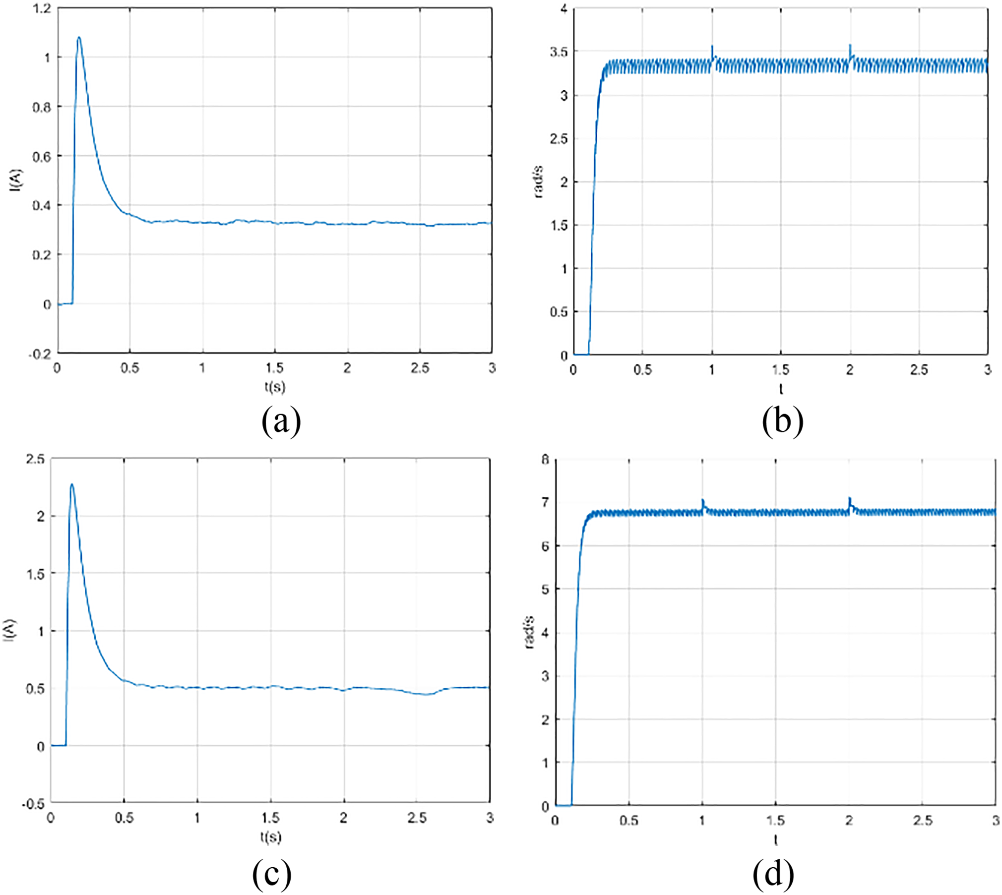

In the same way, the joint 2 with
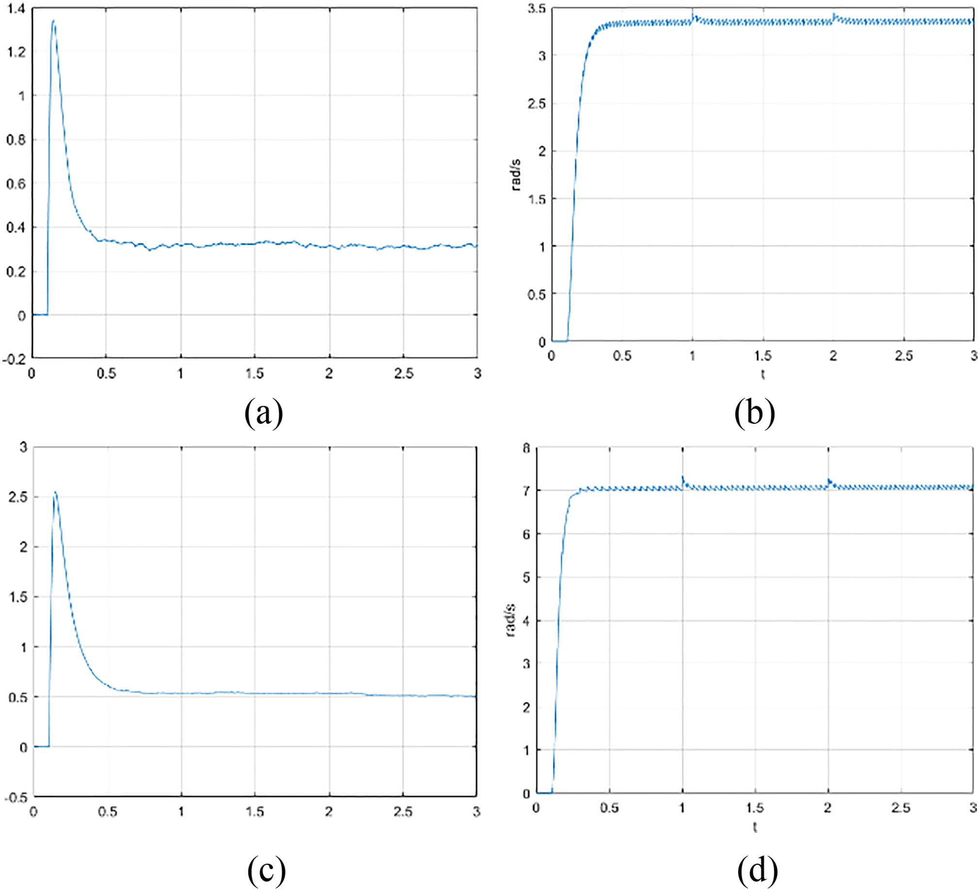
Experimental response of the driving motor at joint 2 when the power supply is 12 V ((a) current and (b) angular velocity) and when the power supply is 24 V ((c) current and (d) angular velocity).
From these computations,
Experimental response of the driving motor at joint 3 when the power supply is 12 V ((a) current and (b) angular velocity) and when the power supply is 24 V ((c) current and (d) angular velocity).
We estimate the gains of the motor model for joint 3 as below:


Description of the proposed robotic platform, (a) the 3D model, and (b) the real-world model.

Experimental result of the tracking performance for the proposed robotic platform.
To monitor the working performance of the driving motors, Figure 16 demonstrates the practical results of direct currents and rotational angles in each one. From Figure 16(b) and (d) to (f), the tracking velocities are nearly identical, with the most noticeable linear change in this value occurring between 1.0 and 1.5 seconds. Therefore, the rotational angle would be initially observed at 1.5 seconds. In fact, the roles of the three motors are quite different. While both motors 1 and 2 drive the parallelogram mechanism, the third motor drives our base around the z-axis and provides flexible motion for this platform. In this case, when the whole system activates at 1.0 seconds, the currents of the three motors in Figure 16(a), (c) and (e) fluctuate since they try to hold mechanical components in the fixed position. Besides, motor 3 slightly moves to adjust the proper location as our desired command at 2.6 seconds. Whenever it comes to the target location, all motors continue to sustain their performance.
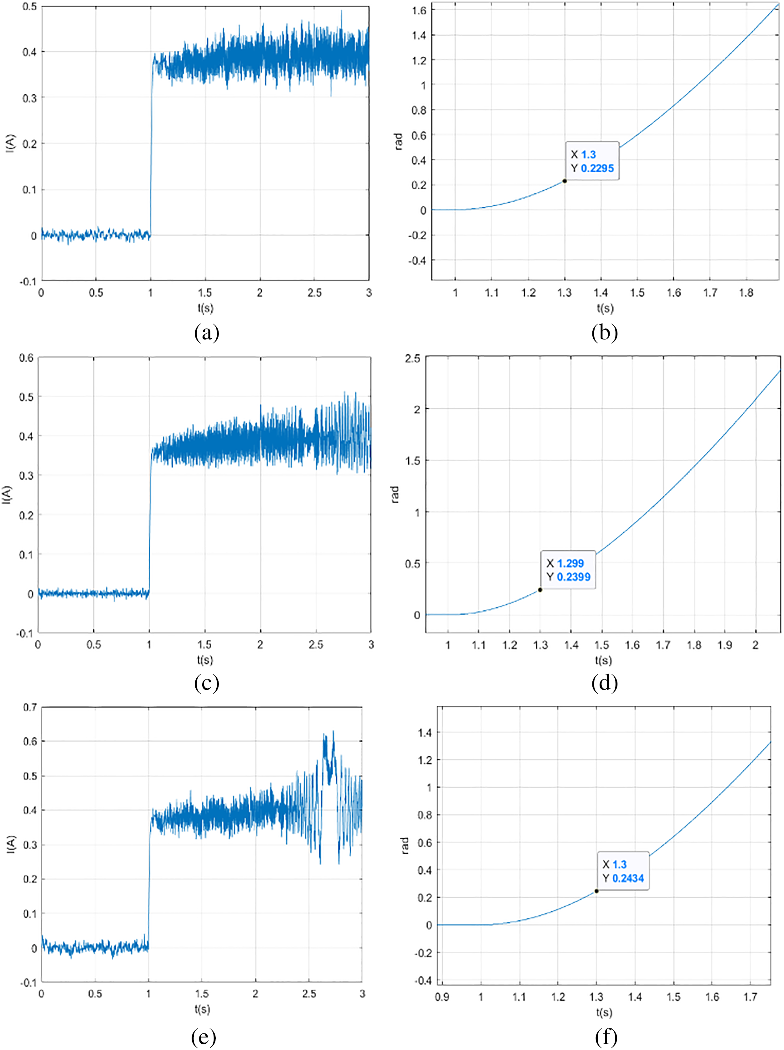
Experimental result of the direct current (a, c, e) and rotational angle (b, d, f) in motor 1, motor 2, and motor 3 respectively.
Conclusions
In this investigation, a comprehensive solution for robotic design using a parallelogram mechanism is presented. Our objectives are to: (i) demonstrate the theoretical computations of both forward and inverse kinematics, as well as validate dimensions and displacement in the mechanical design; (ii) derive the dynamic analysis of the proposed platform to assess its tracking performance; and (iii) fully develop an experimental platform for a laboratory robot to carry out various validations.
Future work is essential. Mechanical improvements for a specialized gripper should be explored to enable the grasping of various objects. Additionally, advanced algorithms for end-effector manipulation, such as adaptive schemes, model predictive control, or intelligent control, could be considered. Moreover, integrating image processing techniques with artificial intelligence may further enhance the quality of grasping actions.
Footnotes
Acknowledgements
We acknowledge Ho Chi Minh City University of Technology (HCMUT), VNU-HCM for supporting this study.
Author contributions
Thanh Phuong Nguyen: data curation, methodology, and supervision; Hung Nguyen: investigation, formal analysis, and visualization; and Thinh Ngo: conceptualization, validation, and writing–review and editing.
Declaration of conflicting interests
The author(s) declared no potential conflicts of interest with respect to the research, authorship, and/or publication of this article.
Funding
The author(s) received no financial support for the research, authorship, and/or publication of this article.