
Abstract
In the practical engineering applications of multi-body floating wave energy converter (WEC), the traditional geometric optimization is always expensive and time-consuming. This study aim to propose a more efficient geometry optimization strategy with a hinged double-body floating WEC as the study object. The influences of geometric parameters of the buoys on the pitching motion and energy conversion ability are analyzed by numerical simulation. Simulation results show that the resonance state of the pitching motion of the buoys mainly depends on their radius and draft rather than the length; But the length of the buoys, rather than the radius and draft, always has a significant effect on the pitching phase difference of the adjacent buoys. Based on the motion analysis and resonance response, an efficient multi-factor geometry optimization strategy is put forwarded. By the strategy, the sub-optimal and optimal geometrical parameters are solved out quickly at several typical wave conditions of China Seas. The results indicate that the optimal total length of WEC is approximately equal to the wave length. The optimal diameter of buoys is about 25% of the length of buoys. And the optimal draft should attain about 61% of the diameter.
Introduction
Ocean wave energy has significant advantages of wide resource distribution, abundant reserves, good energy quality, and easy realization of multi-energy complementarities compared with other renewable energy sources.1–3 It is conservatively estimated that the effective energy of wave energy available for development in coastal areas of China, offshore and adjacent areas is about 576 GW. And the annual wave energy available for mining is equivalent to 618 million tons of standard coal which can reach 14.4% of the total energy consumption of China in 2015. 4 Therefore, large-scale development and utilization of wave energy can effectively alleviate the constraints of fossil fuel and environmental degradation. Wave energy is regarded as one of the most promising renewable energy sources with considerable potential economic benefits, 5 especially in remote communities where conventional energy is lacking. The main coastal developed countries, such as Britain, Sweden, Norway, the United States and Japan, have been developed various types of wave energy converter (WEC) according to the actual conditions of the sea.6,7 So far, more than 1000 WEC patents have been granted since the late 18th century. 8
The main application of WEC is power generation. Besides, there are a few types of WECs that are used for seawater desalination, which can be comparable to the solar desalination devices with good application value.9–11 However, due to the high cost of power generation and immature technology, the commercial application of wave energy is still very limited. It will provide a cost-sharing solution by combining wave energy extraction and coastal protection to accelerate the commercialization of wave energy utilization. 12 Benefit from in-depth research on various types of offshore renewable energy sources, the integrated generation system consisting of wave energy, solar energy or wind energy is expected to improve the stability of power output. 13
According to the working mechanisms, WEC can be categorized as oscillating water column (OWC), overtopping (OWEC) and oscillation floating buoy. The oscillation floating buoy is further divided into two basic types: the single-body floating WEC and the multi-body floating WEC. Most of the single-body floating WECs are the bottom-referenced heaving buoys that the buoys make heaving motion relative to the sea based or the other fixed marine structure. 14 Unlike the single-body device, the PTO (power take-off) of the multi-body floating WEC is usually driven by the relative motion of adjacent buoys during the energy conversion. Therefore, compared to the single-body system, the multi-body floating WEC always perform better in terms of water depth adaptability, wave adaptability and system survivability. The working process and wave energy conversion principle of multi-body floating WEC are described as follow: the buoys motion in waves under the influence of wave force. The asynchronous pitching motions of buoys cause relative motion between the adjacent buoys. The PTO units mostly use the hydraulic energy conversion system, which means that it is a combination of a mechanical/electrical and many hydraulic components. The PTO units are installed between adjacent buoys by multiple sets of hydraulic cylinders. The relative motion of buoys pushes the pistons of the hydraulic cylinders to produce high-pressure oil. The high-pressure oil flows through the hydraulic components, such as control valves, throttles and accumulators, and then drives the hydraulic motor to rotate. Finally, the generator coaxial with the hydraulic motor rotates to generate electricity. Thus, wave energy is converted into available electricity.
Among the developed multi-body floating WEC, the most famous is the ‘Pelamis’ wave power generation system developed and built by the Pelamis Wave Power Ltd (PWP) in Scotland, which is also considered as the world's first commercial-scale wave power system. As a type of line wave energy absorber, their theoretical capture width limits can reach 0.50 λ to 0.73 λ (λ is wave length) depending on the length of devices. In a quite long-term trials and operation, this WEC has been proved to have excellent wave energy capture capability and excellent high sea state survivability. 15 In addition, the well-known multi-body floating WECs that have been developed and researched include Hagen-Cockerell raft, 16 McCabe Wave Pump 17 and so on.
To promote the application of the multi-body floating WEC in China, Biao Li and Hongtao Gao also have developed a series of researches on this type of WEC. 18 Several sea trials of the small-sized devices have been carried out at Dalian sea area of China Yellow Sea and Bohai Sea in 2012 and 2013 (Figure 1). The devices are constituted of multiple section cylindrical buoys hinged together by several hydraulic energy conversion units. 19 The purpose of these sea tests is to verify the feasibility of this type of WEC in China and further explore its wave energy conversion characteristics. The results indicated that the WEC has good practicability and application prospect. Currently, the experiments are still ongoing.

Sea tests of the small-sized WECs developed by Biao Li and Hongtao Gao in November 2013.
It is essential to carry out the researches on the performance prediction and optimization design for a WEC to capture and extract as much wave energy as possible from the ocean. The performance will be influenced and optimized by the geometrical parameters of buoys and PTO dampers (including springs). And many optimization methods have been put forward based on the principle of maximizing the wave energy conversion efficiency. For the PTO damping, the influences of simplified linear and nonlinear damping have been demonstrated in some studies that mainly focused on the point absorber,20,21 such as oscillation floating buoy. In the research of the WEC consisting of two interconnected floaters, Zheng explored the performance of the two floaters was with the linear PTO dampers. Then the maximum wave energy conversion and optimized PTO system have been studied by numerical simulation. 22 The performance of power capture of a novel hydraulic PTO that is installed on the Pelamis WEC has been assessed through numerical simulation and experiment. 23
To investigate the influences of the geometrical parameters of buoy, Haren and Mei theoretically studied the hydrodynamics characteristics and efficiency response of Hagen-Cockerell rafts in 1970 s.24,25 In their research, an optimization method of number of rafts is described with a linear hydraulic PTO system. In the research of the conversion efficiency of a raft-type WEC by Chen and Zhang, the pitching motions of raft were presumed to be full axisymmetric. 26 For some other similar devices with the buoys of elliptical or rectangular cross-section, the influences of geometrical parameter of buoys have also been investigated.7,27,28 In the studies of the multi-body hinge-barge WEC, the size of barge was optimized by Wang and Ringwood based on a multi-DOF mathematical model with the objective of maximum extracted energy under given sea states. Furthermore, they found that the three-body hinge-barge device tends to perform like a two-body system under optimal control conditions. 29 In solving the dynamics model of three-body hinge-barge device, F. Paparella and G. Bacelli applied the pseudo-spectral (PS) methods to describe the motion response of multi-body system more conveniently. 30 In further research by Paparella, an optimal control strategy related to the buoys motion and PTO loads was proposed, so that the total energy extracted by the device was maximized. 31 In addition, taking large arrays of hinged structures as the research object, Lee developed a computational methodology to discuss the hydroelasticity effect with structural stiffness parameters. 32 A multi-objective optimization strategy of a flexible floating structure with linear hydraulic PTO mechanisms was developed for wave energy production and protection effectiveness. 33
For most WECs that have been studied, the traditional geometry optimization is usually carried out through many expensive and time-consuming physical model experiments, or inefficient and repetitive numerical simulations, with the goal of maximum wave energy conversion efficiency.34,35 To the author’s knowledge, no researcher has explored the topic of buoy geometry optimization from the perspective of the kinematic coupling relationship and resonance characteristics of multiple floating buoys. This paper takes a hinged double-body floating WEC as the study object. The equations of buoy motion and wave energy conversion are established based on hydrodynamic theory. Then the sensitivity study on the effect of geometric parameter of the WEC is investigated by analyzing the relationship between the pitching motion of buoys and the energy conversion ability. 36 According to the mechanisms of resonance and phase different feature of adjacent buoys, a more efficient multi-factor geometry optimization strategy is put forwarded, which can greatly reduce the amount of experiments or calculations required by traditional optimization methods. Finally, the sub-optimal and optimal geometrical parameters are solved in typical China seas.
Theory and model
Model description
The configuration schematic of the hinged double-body (L-Buoy and R-Buoy) floating WEC is depicted in Figure 2. The wave energy conversion unit is composed of two PTO dampers and springs. The main function of the springs is to provide partial restoring force for the buoys. During this motion of buoys, the wave energy are stored and released periodically by the springs to make the energy output more stable. The two buoys are of the same geometric size and weight that evenly distributed. In the equilibrium state, the horizontal distance between the buoys is l.
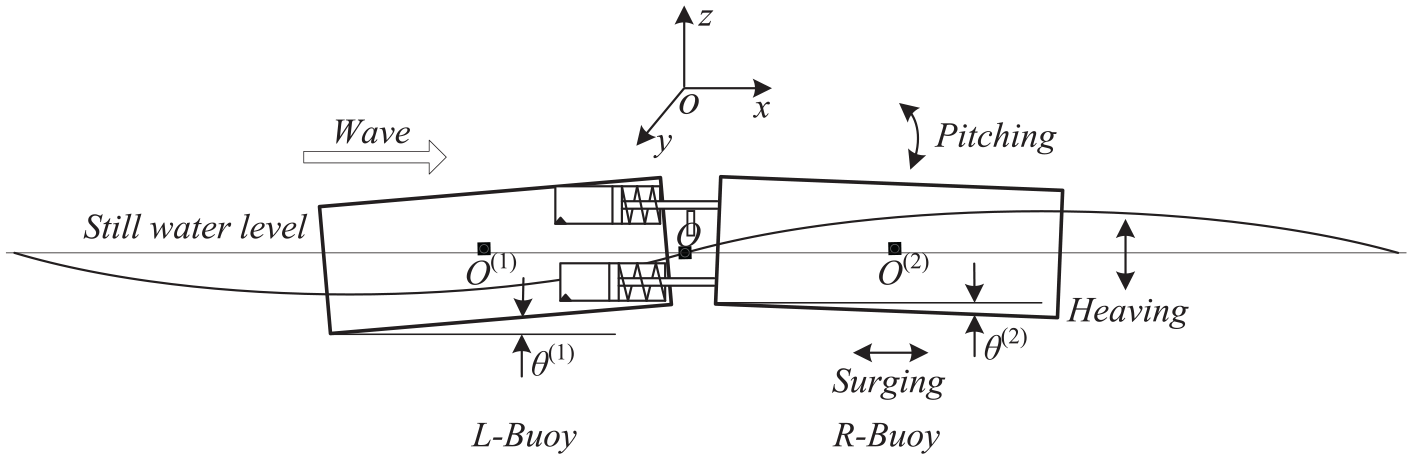
Configuration schematic of the hinged double-body floating WEC.
In the stable running of WEC, the motions of surging, heaving and pitching are worth to be considered. The flow is assumed to be inviscid, incompressible and irrotational. The kinematic equations of buoys are expressed as 37 :
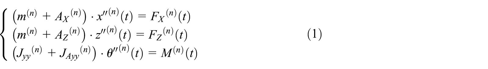
Where
According to the analysis of the motion and geometric relationship between adjacent buoys, the following geometric equations are derived:

Thus, the motion of the hinged double-body floating WEC is depend on the kinematic equation (1) and geometric equation (2).
Conversion power and relative capture width
The damping forces of PTO

Here
The conversion power


Where
In this paper, the relative capture width

Where

Where
In this mathematical model, the necessary hydrodynamic parameters and physical parameters are calculated from the numerical simulation of STAR-CCM+. These parameters include the wave excitation force, wave radiation force, damping force of PTO, added mass and added mass moment of inertia. In the calculation of the motion model equation, the linear and regular wave model is adopted, thus the mathematical model can be converted into the frequency-domain equation that can be solved quickly by the calculation program compiled on the MATLAB/SIMULINK platform. Finally, the pitching angular displacement and phase differences of the buoys with different buoy geometry and wave frequency are obtained. And from these motion parameters, the conversion power and relative capture width are calculated.
Numerical simulation
The dynamic mesh and numerical wave flume are applied in the numerical simulation based on the STAR-CCM+ which is a type of multi-physics simulation software developed by Siemens AG. The water waves are treated as linear and regular waves. The meshes of buoys and numerical wave flume for finite element method (FEM) are shown in Figure 3. The local mesh refinement method is presented in buoys and wave surface.

The meshes of buoys and numerical wave flume: (a) the mesh generation of buoys and (b) the mesh generation of numerical wave flume.
Figure 4 is the calculation region of this simulation. The scale of the calculation region is 150 m (length) × 100 m (width) × 50 m (height). It is can be seen from the figure that the wave form and buoys motions are displayed clearly with this mesh density.
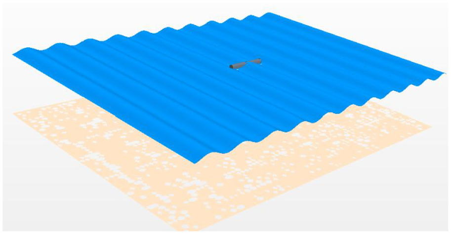
Calculation region.
Figure 5(a–d) are the time-domain scalar figure of WEC motion in regular waves. The wave period T is 3.0 s and the wave height H is 1.2 m, which are based on the wave survey of China Yellow Sea and Bohai Sea completed by the Dalian Weather Bureau. In these figures, t = 0.0 s, t = 4.5 s, t = 9.0 s and t = 13.5 s represent the different instantaneous physical moments of the numerical simulation.39,40 It is can be seen that the motion states of buoys are obviously different at different instants of time.

The scalar figure of WEC motion at different instants of time (T = 3.0 s, H = 1.2 m).
This numerical simulation can also solve the motion of the buoys. However, because the calculation process is a transient simulation, it takes too long to reach the state where the buoys motion changes periodically with the waves. This will result in low efficiency and excessive calculation. Therefore, this numerical simulation is mainly suitable for solving the hydrodynamic parameters necessary for the mathematical models.
Model validation
The research of the hinged double-body floating WEC has been previously investigated by using a numerical model. As shown in Figure 6, with the same parameters of waves and devices, the variation curve of the maximum relative capture width with dimensionless radius of gyration is plotted based on the motions model established in this paper. The result shows that the present result has good coherence with the data calculated by Zheng on the whole. 26

Variation of the maximum relative capture width with dimensionless radius of gyration
Motion analysis
The main purpose of this paper is to optimize the geometry of the buoys. However, the PTO parameters also have a significant impact on the motion response and wave energy conversion of the WEC. Through the analysis of the influences of PTO parameters, the selection principle of PTO parameters can be clarified in theory. Figures 7 and 8 show the pitching motion and relative capture width with the viscous damping coefficient C of PTO and stiffness coefficient K of springs, respectively.

Pitching motion and relative capture width with PTO damping coefficient C.
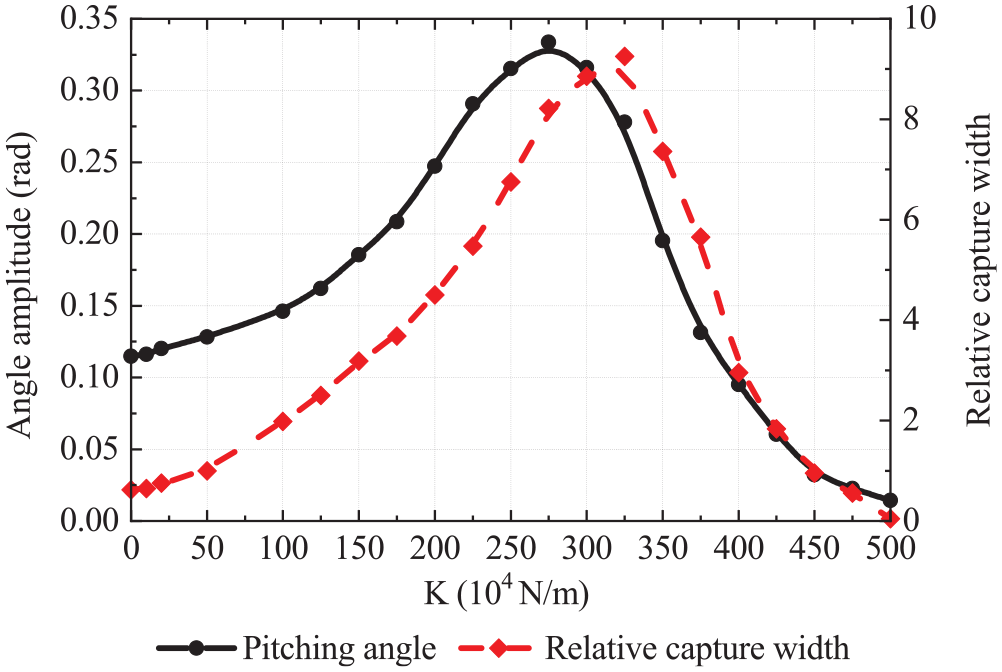
Pitching motion and relative capture width with spring elasticity coefficient K.
It can be seen that with the increase of the PTO damping coefficient or spring elasticity coefficient, both the angle amplitude of pitching motion and relative capture width continue to increase in a wide range. This is also a significant feature of the multi-degree-of-freedom motion of the multi-body system different from that of the single-body system. 20 In theory, under a certain wave parameter, the optimal PTO damping coefficient and optimal spring elasticity coefficient may be very large, so that the theoretical optimal dampers are almost impossible to apply in actual engineering. Therefore, in the design or test of this type of WEC, the PTO damping parameters should be set to the maximum values within a certain range according to the actual situation of the device and wave field.
Parameters and characteristic of pitching motion
In order to clarify the influence of the geometrical factors on buoy motion and wave energy conversion, the PTO parameters including the viscous damping coefficient and the stiffness coefficient of springs are all set to the fixed values. The damping coefficient of PTO damper C is 7.5 × 10⁴ N·s/m, the stiffness coefficient of restoring springs K is 10 × 104 N/m. The wave height H is 1.2 m. Since the wave energy conversion of this WEC depends only on the relative pitching angular displacement between the adjacent buoys, only the pitching motions of buoys are discussed herein.
Different from the single buoys wave energy absorber, the factors, which influence the dynamic response of multi-floating WEC, are not only the motion of buoys but also the phase difference of adjacent buoys. The pitching motions and phase difference of buoys with wave circular frequency are shown in Figure 9. In the numerical simulation, it is found that the pitching amplitudes of the two buoys are almost equal with the same wave circular frequency. Since the lengths of the two buoys are the same, the relative angular displacement of the adjacent buoys, related to the wave energy conversion, only depends on the pitching angle and phase difference of the adjacent buoys. The resonance phenomenon of the buoys appears as the maximum value of the pitching motion in the graph. It can be seen that, unlike the motion performance of the traditional single buoy, when the buoys resonance occur or the phase difference of adjacent buoys is odd multiples of 180°, the relative pitching angular displacement may have a maximum value.
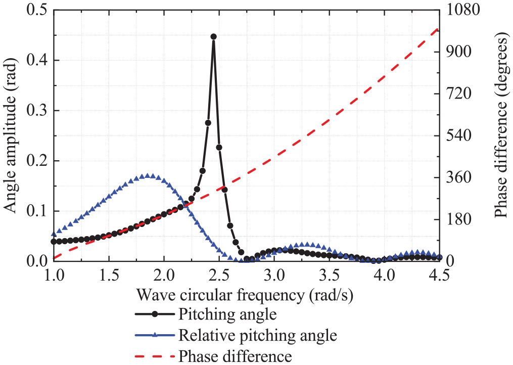
Pitching motions and phase difference of buoys with wave circular frequency.
Performance of the WEC with length of buoy
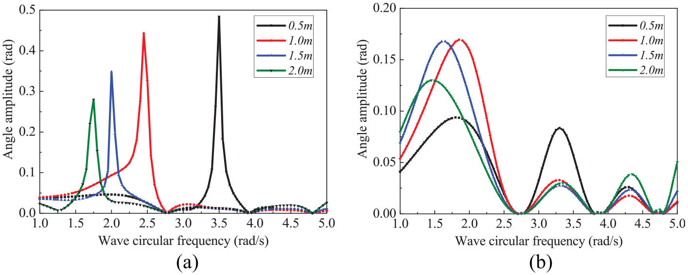
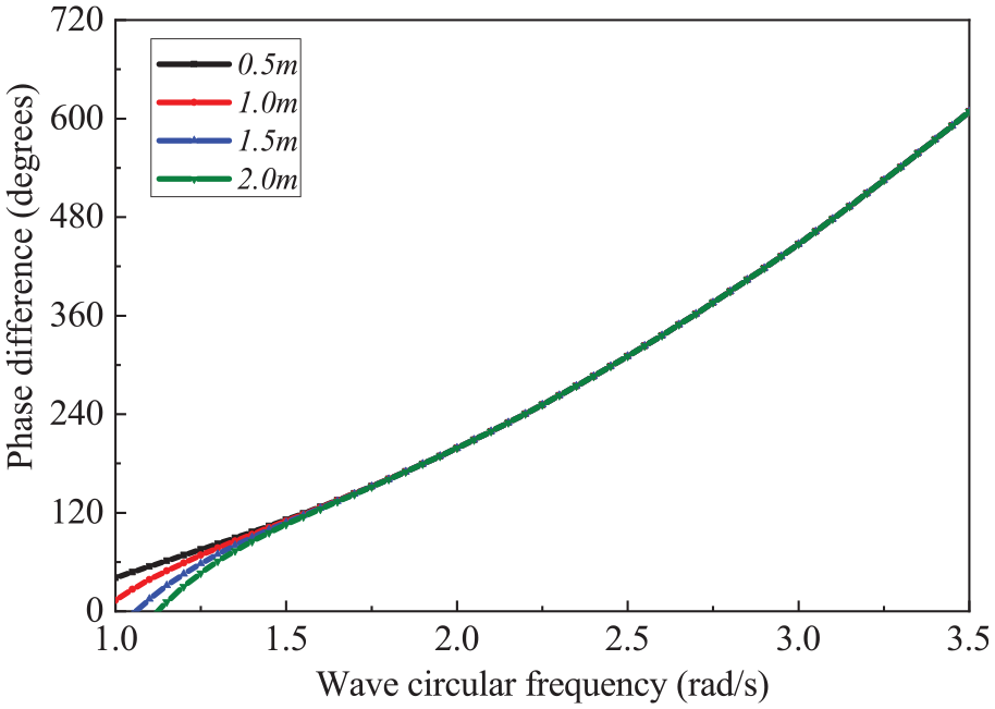
Figure 10(a) and (b) show the features of pitching motion with length of buoy (R = 1.0 m, Dr = 1.0 m). For the buoys of different lengths, the maximum values of the pitching angles always appear at a fixed wave circular frequency that is the resonance frequency. As shown in Figure 11, the length of buoy has significant effect on the phase difference at the investigation wave circular frequency of 1.0 rad/s to 3.5 rad/s. Obviously, the curve of relative pitching angles also show multiple extreme values and zero values.

Pitching motion features with length of buoy: (a) Pitching angle and (b) Relative pitching angle.

Phase differences with length of buoy.
The relative capture width with length of buoy is shown in Figure 12. Through the analysis of the data, when the length of buoy is 7.9 m and the wave circular frequency is 1.95 rad/s, the relative capture width will reach its maximum. In this state, the phase difference is 180°, although the buoy is not in resonance state.

Relative capture width with different length in the wave circular frequency range of 1.0 rand/s to 4.0 rad/s.
Performance of the WEC with radius of buoy
The performances of pitching motion with radius of buoy are plotted in Figure 13 (a), (b) (L = 8.0 m, Dr = R). For the buoys of different radiuses, the maximum values of the pitching motion at different wave circular frequencies are all very significant. The reason is that the smaller the radius of buoy, the greater its natural inherent frequency. The features of phase differences are presented in Figure 14. In general, when the wave circular frequency exceeds 1.50 rad/s, the change in the radius of buoy does not affect the phase difference. However, when the wave frequency is less than 1.5 rad/s, due to the relatively small wave force on the buoys, the influence of the radius on the phase difference cannot be ignored.
Pitching motion features with radius of buoy: (a) Pitching angle and (b) Relative pitching angle.
Phase differences with radius of buoy.
As shown in Figure 15, the relative capture width is also affected by the radius of buoy. Through the analysis of the data, when the radius of buoy is about 1.2 m and the wave circular frequency is 1.95 rad/s, the relative capture width will reach the maximum that is about 0.98. In this state, the buoy is in resonance state and the phase difference is 180°.

Relative capture width with radius of buoy.
Performance of the WEC with draft of buoy
The performances of pitching motion with draft of buoy (L = 8.0 m, R = 1.0 m) is shown in Figure 16(a) and (b). For the pitching angle of buoys, as the draft increases, the wave circular frequencies corresponding to the peaks of the curves gradually decreases. It could be attributed to the altering of natural vibration frequency caused by the change of the mass of buoy. According to the observation of Figure 17, the change in the draft of buoy does not affect the phase difference, which is similar to the effect of radius.

Pitching motion features with draft of buoy: (a) Pitching angle and (b) Relative pitching angle.

Phase differences with draft of buoy.
Figure 18 shows the curves of relative capture width with draft at different wave circular frequencies. If the relative capture width of the WEC is to be maximized, the draft should be about 1.5 m, and the corresponding wave circular frequency is 1.90 rad/s. Under these conditions, the buoys are in resonance with the waves, and the pitching phase difference of adjacent buoys is 180°, that is, the relative pitching angle is the sum of the pitching angles of the two buoys.
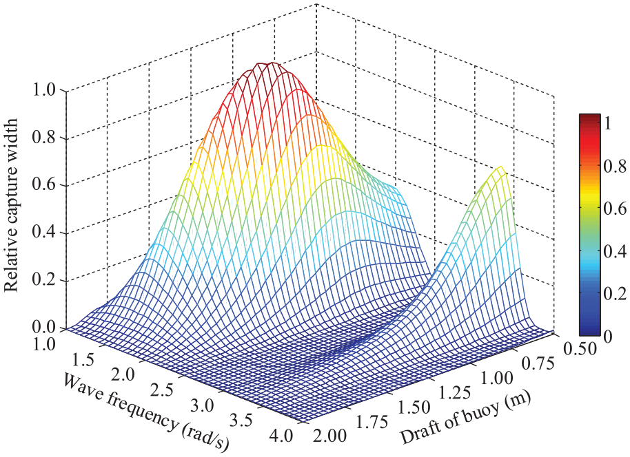
Relative capture width with draft of buoy.
Geometry optimization
Geometry optimization procedure
Generally speaking, for the given WEC with fixed PTO parameters, there is always a set of optimal geometry parameters of buoy that makes the relative capture width to attain its maximum at certain wave condition. In theory, the relative capture width is mainly affected by wave period rather than wave height. Therefore, we only need to consider the geometry optimization at different wave periods or wave circular frequencies. From the previous analysis of influencing factors, the conclusions are summarized as follows: (1) the resonance state of the pitching motion of the cylindrical buoys in waves mainly depends on the diameter and the mass of the buoy (buoy draft). However, the buoy length has almost no effect on its resonance frequency. (2) The buoy length always has a significant effect on the phase difference of adjacent buoys. However, the diameter or mass of buoy generally have no obvious effect on the phase difference.
According to the analysis of the buoy motion, when the phase difference of adjacent buoys is odd multiples of 180°, the relative pitching angle is the sum of the pitching angles of the two adjacent buoys. In addition, the phase difference depends only on the length of buoy. In this paper, the length of the buoy that meets this condition is defined as the optimal length.
Figure 19 is the curve of optimal length of buoy with wave length, which is calculated by the numerical simulation method described above. It is clear that the optimal length of buoy is nearly proportional to wave length.

Optimal length of buoy with wave length.
By analyzing the motion law of the articulated multi-floating system, the phase difference is introduced as an independent influencing factor into the traditional optimization method based on the buoy resonance. Thus, the geometry optimization procedure of the buoy related to multiple wave elements is put forward as the follow procedure (Figure 20). According to these optimization steps, a series of sub-optimal geometrical parameters would be solved quickly, at which the values of relative capture width are considerable, and the resonances occur and phase differences are 180°. From these sub-optimal geometrical parameters, the optimal geometrical parameters can be found out, at which the relative capture width reaches peak at the given wave period. Obviously, this multi-factor geometry optimization procedure is efficient and easy to implement, which can greatly reduce the amount of calculations or experiments required by traditional optimization methods.

Geometry optimization procedure of the buoy.
Geometry optimization result
By the geometry optimization procedure, the optimal lengths of buoys are calculated at several typical wave periods of China Yellow Sea and Bohai Sea40,41 with the wave height of 1.2 m. Then the optimization graphs of geometrical parameters of buoy are plotted in Figure 21(a–f). And a series of sub-optimal geometrical parameters corresponding to any radius or draft are displayed clearly. Finally, the optimal parameters of radius and draft are found out from the optimization graphs at a given wave period.
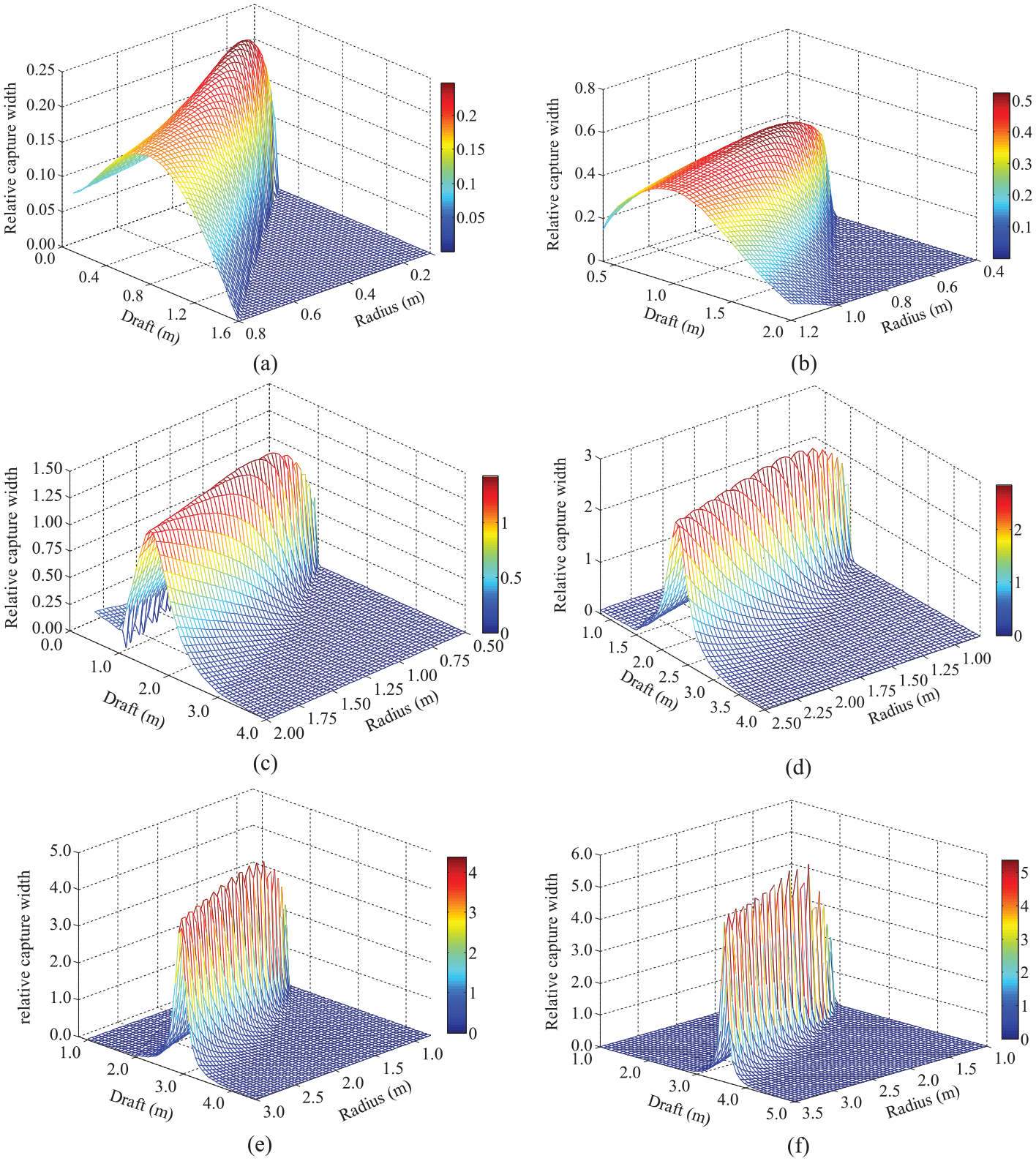
Optimization graphs of geometrical parameters of buoy at several typical wave periods: (a) T = 2.5 s, L = 4.5 m, (b) T = 3.0 s, L = 6.6 m, (c) T = 3.5 s, L = 9.1 m, (d) T = 4.0 s,L = 12.1 m, (e) T = 4.5 s, L = 15.4 m, and (f) T = 5.0 s, L = 19.3 m.
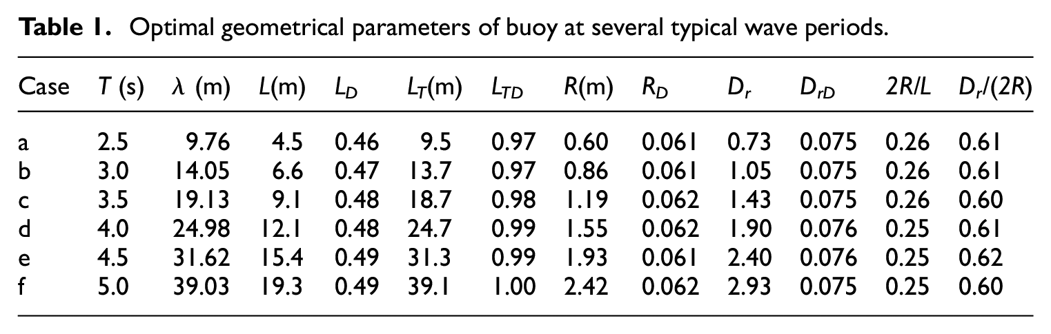
In order to make the optimization results more regularity, the optimal total length (LT = 2L+l), draft (Dr) and radius (R) are converted into proper dimensionless indexes. The dimensionless methods are denoted by the following formulas.

Where
As shown in Table 1, the optimal dimensionless parameters of the buoy length, total length of WEC, draft and radius are respectively about 0.48, 0.99, 0.061, and 0.075. That is, the optimal total length of device
Optimal geometrical parameters of buoy at several typical wave periods.
Conclusion
In this paper, under the condition of linear waves, the frequency-domain motion response of a multi-section WEC is carried out by means of numerical simulations. Effects of length, radius and draft of buoy on the pitching motion and relative capture width were explored with the fixed linear damping and spring coefficient. Simulation results show that the resonance state of the pitching motion of the cylindrical buoys in waves mainly depends on the radius and the draft of the buoy rather than length. However, the length of buoy, rather than radius and draft, always has a significant effect on the phase difference of adjacent buoys. According to analysis of influencing factors, an efficient multi-factor geometry optimization strategy of buoy is put forward based on pitching motion analysis and resonance response. Then the geometrical parameters of buoy are calculated at the typical wave condition of China Yellow Sea and Bohai Sea. The optimal total length of device is approximately equal to the wave length. The optimal diameter of buoy is about 25% of the length of buoy. And the optimal draft of buoy should attain about 61% of the diameter.
Future work will consider geometry optimization of the linear absorber with more than two buoys as well as the influences of nonlinear damping.
Footnotes
Appendix
Acknowledgements
The authors extend their thanks to Liaoning Maritime Safety Administration of the People’s Republic of China for the help to make the sea tests go through.
Declaration of conflicting interests
The author(s) declared no potential conflicts of interest with respect to the research, authorship, and/or publication of this article.
Funding
The author(s) disclosed receipt of the following financial support for the research, authorship, and/or publication of this article: This work was supported by the Scientific Research Initializing Fund of Jiangsu University of Science and Technology [grant numbers 1142931705]; the Open Fund of Zhenjiang Marine Power Equipment Characteristic Key Laboratory [grant numbers 10331910].
Data Availability Statement
Some data used to support the findings of this study are included within the article. All the other data and models used to support the findings of this study are available from the corresponding author upon request.