
Abstract
As a novel flying-wing configuration underwater glider, the blended-wing-body underwater glider (BWBUG) has the satisfactory hydrodynamic performance in comparison to the conventional cylindrical autonomous underwater gliders (AUGs). The complicated shape optimization of BWBUG is significant for improving its hydrodynamic efficiency while it has to require huge computation time and efforts. A novel surrogate-based shape optimization (SBSO) framework is proposed to deal with the BWBUG shape optimization problem for improving the optimization efficiency and quality. During the optimization search, the parametric geometric model of the BWBUG is constructed depending on seven specific sectional airfoils, with the planar surface being unaltered. Moreover, an improved ensemble of surrogates based global optimization method using a hierarchical design space reduction strategy (IESGO-HSR) is used for optimizing the chosen sectional airfoils. The optimum shape of BWBUG can be obtained using all sectional airfoils which are successfully optimized. The maximum lift to drag ratio (LDR) of the optimal BWBUG is improved by 24.32% with acceptable computational resources. The optimization results show that the proposed SBSO framework is more superior and efficient in handling the BWBUG shape optimization problem.
Introduction
AUGs rise and sink across the ocean by changing the buoyancy and converting the lift into propulsive force to propel themselves forward autonomously. 1 Being endurable and remote, AUGs provide a platform for long-term oceanic application and fill in the gap left by short-term unnamed underwater vehicles and existing manned submersible vehicles. To face with the challenges of oceanographic exploitation and exploration programs, intensive efforts have been made to the development of sea-worthy AUGs.2–4 Hussain et al. 5 presented the modeling and identification on net buoyancy, pitching angle and depth of an AUG system. Zamuda et al. 6 proposed a constrained differential evolution optimization approach to tackle the AUGs path planning. Fu et al. 7 used the multi-objective optimization algorithm NSGA-II to optimize the slender ellipsoid shapes of AUGs. Most researchers prefer to opt for the cylindrical structure shapes referring to the torpedoes and submarines. 8 Although the classical cylindrical shapes can provide the better structural efficiency, they are considered as less efficient in terms of hydrodynamic performance especially for LDR. As a new type of AUGs, the body of BWBUG is blended and smoothed into the separate and distinct wings. 9 The superiority of this blended-wing-body configuration lies in smaller wetted area to volume ratio and larger LDR. However, the hydrodynamic shape optimization is rarely applied in case of the BWBUG design while the available optimization tools and design approaches are not adequately efficient to be adopted within a given optimization target. Advancement of surrogate-based optimization (SBO) methods for complicated BWBUG shape optimization problem has attracted much attention recently. Sun et al. 9 used the efficient global optimization (EGO) method to achieve the higher maximum LDR of BWBUG. Wang et al. 10 introduced a multi-objective optimization method using the Gaussian kernel function to balance the LDR and moment of BWBUG.
In the authors’ previous study, 11 a novel ensemble of surrogates based global optimization method using a hierarchical design space reduction (ESGO-HSR) strategy was proposed to enhance the accuracy, efficiency and robustness for solving the real-world engineering applications. In this work, the IESGO-HSR method based on the improvement of the recently presented ESGO-HSR method 11 is applied to solve the BWBUG shape optimization problem. A 3D BWBUG shape can be regarded as a group of sectional airfoils across the wing span. 9 In other words, the optimum shape of the BWBUG can be achieved using a set of important sectional airfoils that are successfully optimized. This simplification is conducive to efficient determination of the acceptable approximation solutions while the complicated shape of BWBUG may raise difficulties during the search. Moreover, the class function/shape function transformation (CST) approach is employed for parameterizing the sectional airfoils. 12 The open code Computational Fluid Dynamics (CFD) packages XFOIL is adopted to analyze the flow around the chosen sectional airfoils, that is, baseline airfoils of BWBUG. 13
A novel SBSO framework is presented in this work to efficiently complete the optimum shape of the BWBUG under the given operating conditions, that is, the angle of attack AOA = 7° and the velocity v = 1 m/s. First, CST method is employed to parameterize the key baseline airfoils. Second, the IESGO-HSR method is employed to find the optimal baseline airfoils with the maximum LDR. Meanwhile, two constraints on the cross sectional area and the maximum thickness of baseline airfoils need to be strictly satisfied during optimization. Finally, the optimum shape of BWBUG can be achieved using the optimal baseline airfoils obtained. The hydrodynamic performance of the optimal BWBUG is calculated and analyzed to demonstrate the validity and superiority of the newly presented SBSO framework.
CST method
To parameterize the initial BWBUG shown in Figure 1, many specific sectional airfoils are adopted to model the hydrodynamic shape, with the planar surface being stationary in this study. The BWBUG shape is built by Unigraphics NX (UG) software based on seven typical and symmetric NACA 00XX series airfoils named XF1∼XF7 with the chord lengths of c1∼c7. Figure 2 shows an illustration of the parameterization of the hull geometry, including the horizontal distances between seven airfoils and the origin l1∼l7, and the vertical distances between the leading edges of seven airfoils and the origin d1∼d7. The leading edge of XF1 is selected as the origin in this work. The planar surface of the BWBUG is fixed and determined by fourteen control points, that is, leading and trailing edges of seven baseline airfoils using UG. Moreover, the baseline airfoils are also employed to determine the thickness of any section of the airfoil by means of UG software. 14 The related design parameters are listed in Table 1.

Initial BWBUG shape.
Parameterization of the hull geometry.
Parameters of the baseline airfoils.

The CST method is employed to parameterize the sectional airfoils with a small variety of variables in this work. The CST parameterization model of the sectional airfoil can be written as
where c is the chord length, n represents the order of Bernstein polynomials, yu0, yl0, yu and yl are the upper and lower surfaces of the basic airfoil and target airfoil, respectively. The weight factors Aui and Ali, in turn, indicate the design variables for the upper and lower airfoil shape optimization, separately. Moreover, the parameters N1 = 0.5, N2 = 1.0 are selected for a sharp trailing edge and round nose airfoil in this work. More details on CST can retrieve from literatures.12,15,16
As expressed in equation (1), there are n+ 1 variables for upper and lower surfaces with nth-order Bernstein polynomial, respectively. The design parameters Aui and Ali can be calculated by using the least square error method, where the error is estimated by the L2 norm of the difference between the parameterization model and the actual model. Figure 3(a) draws the fitting curve of a symmetric airfoil NACA 0021 on the basis of the airfoil NACA 0018 with 4th-order Bernstein polynomials. Figure 3(b) shows the error of such fitting as a function of the order of the parameterization. This error profile shows the similar characteristic with other sectional airfoils. As described in Figure 3(b), the fitting accuracy is nearly higher while larger n is used. Moreover, the fitting accuracy remains stable when n≥ 4. Kulfan 12 also suggests that n = 4–6 is large enough for fitting a NACA airfoil with acceptable prediction accuracy. Therefore, 4th-order Bernstein polynomials are adopted in this study. It offers a balanced trade-off between the fitting accuracy and computation efficiency.

Geometric representation error analysis. (a) Airfoil parameterized with 4th-order and (b) L2 norm geometric error
Problem formulation
The aim is to maximize the LDR of BWBUG under the given operating conditions, that is, the angle of attack AOA = 7° and the velocity v = 1 m/s involving the constraints about the cross sectional area and the maximum thickness in this work. The BWBUG shape are built by seven specific baseline airfoils that can be parameterized through the CST approach of 4th-order, involving five design variables and thirty-five design variables in total. Five design variables for each axisymmetric baseline airfoil are the weight factors Aui (Ali = –Aui) defined in equation (1), in a vector as

The airfoil shape optimization problem is formulated as below

where L and D indicate the lift and drag of the airfoil respectively, sopt, sini, topt, tini represent the cross sectional area and maximum thickness of the optimal and initial airfoil separately,
In order to avoid abnormal shapes, the upper and lower bounds of variables are given in Table 2 in accordance with the parametric design of the BWBUG. Take the initial airfoil XF1 as an example, assume that the maximum thickness of the optimal airfoil obtained varies within the range between NACA 0017 and NACA 0027. Thus, the lower and upper bounds of design variables for XF1 are determined by using the least square error method to fit NACA 0017 and NACA 0027 on the basis of the NACA 0022 (XF1). Similarly, the upper and lower bounds of design variables for XF2 are calculated by using NACA 0022 and NACA 0012. The upper and lower bounds of design variables for XF3∼ XF7 are both calculated by means of NACA 0010 and NACA 0006. The initial BWBUG shape has been modeled through using seven initial sectional airfoils which are also considered as the initial design scheme during the optimization process as shown in Figure 1. It’s noted that the obtained optimal BWBUG shape is still strictly axisymmetric.
Parameters ranges of design space.
IESGO-HSR method
The IESGO-HSR method improved from an existing ESGO-HSR approach is applied for the shape design of the BWBUG under the given design requirements in this study. More details of the ESGO-HSR approach can be found in the authors’ previous paper. 11 It’s noted that the convergence criterion for IESGO-HSR method is different from the original ESGO-HSR approach. The convergence criterion for ESGO-HSR approach is formulated as follows

where fmin indicates the real global minimum, fopt represents the current best solution, Tol is the allowable error that is used to decide whether the current best solution meet the convergence requirement. The convergence criterion abovementioned is suitable for the computationally expensive black-box problems where the function characteristics are sufficiently gained. In fact, the actual global optima of all test examples are assumed to be known in advance in the authors’ previous paper. 11
However, the global minima of most engineering design optimization problems like BWBUG shape design optimization problems are unknown beforehand. To relieve the computational burden, the IESGO-HSR method improved from an existing ESGO-HSR approach is applied for the shape design of the BWBUG. The IESGO-HSR method involving the modified convergence criterion formulated as equation (5) is employed to solve the BWBUG shape design optimization problems.

where fj indicates the jth smallest function value, ε represents a small value given by the researcher. If the improvement on the average of the five lowest function values becomes negligible, the current best result is considered to be acceptable approximate global optimum. This criterion offers an efficient and practical way to solve the computation-intensive black-box problems with no need for deep knowledge on the characteristics of the problems. The global minima of all test examples are assumed to be undiscovered in this paper. The viability and effectiveness of the IESGO-HSR approach are tested in Section 6.1.
SBSO framework
The newly presented SBSO framework seeks for the optimum shape of BWBUG via four main stages: (a) construct the parameterization models for the initial sectional airfoils using CST approach, (b) estimate the hydrodynamic performances of the sectional airfoils using XFOIL, (c) search for the optimal sectional airfoils using IESGO-HSR method, d) rebuild the optimal BWBUG shape using all optimal sectional airfoils with UG software. The flowchart of the SBSO framework is provided in Figure 4, and summarized into these steps.
Set the index of the chosen baseline airfoil i = 1.
Select the ith baseline airfoil as the optimization object.
Initialize parameters in IESGO-HSR method and n, v, Re, AOA.
Calculate the relevant design space relating to the ith baseline airfoil.
Obtain the initial samples in the aforementioned design space using sample design method translational propagation and successive local enumeration (TPSLE). 17
Construct the airfoil parameterization models involving the new samples using CST method.
Calculate the hydrodynamic performances of the airfoils using XFOIL.
Explore the optimal airfoil through the IESGO-HSR method.
Judge if the present best solution meets the convergence criterion as equation (5), skip to the step 11. If not, skip to the next step.
Generate the new sample points using the IESGO-HSR method, and supplement them to the sample database. Skip to the step 6.
Build the optimum shape for the ith baseline airfoil and store the corresponding optimal parameters.
Check i < 7? If it’s real, i = i+ 1 and skip to the step 2. If not, skip to the next step.
Rebuild the optimal BWBUG shape using seven optimal baseline airfoils by UG software.
Flowchart of the proposed SBSO framework.
The maximum LDR is taken as the optimization target to search for the optimum shape of the BWBUG in this study. The optimal BWBUG shape is rebuilt via the seven optimal airfoils by using UG software. Moreover, this SBSO framework allows the researchers to integrate auxiliary modules and manage the complexity of the optimization problem. It’s able to model and solve various forms of AUG optimization problems according to the user requirements.
Results and discussions
This work aims to obtain the maximum LDR using a newly presented SBSO framework. To investigate the effectiveness and validity of this SBSO framework, the detailed design of the BWBUG has been accomplished to compare with the initial design shown in Figure 1.
Numerical experiments
The effectiveness of the newly proposed SBSO framework is directly affected by the capability of the IESGO-HSR method. Poor optimization method may lead to a local optimum or inaccurate solution. Therefore, the prediction accuracy and efficiency of the IESGO-HSR approach are tested using ten representative numerical examples involving 2 to 16 variables formulated in Appendix 1. Here, all test examples are considered as the computation-intensive unknown problems whereas the actual global optima as well as the function characteristics are unknown in advance. All design parameters in IESGO-HSR method which can refer to the literature 11 are the same for all problems. Furthermore, ε is set to be 0.001 for all test problems.
The computational time is normally proportional to the number of expensive function evaluations (NFE) for computation-intensive black-box problems. Therefore, NFE is used to represent the search efficiency. Meanwhile, the best solution fopt obtained is also taken to show the optimization accuracy. Ten experiments are conducted for all numerical examples to decrease the random variation. The statistical results are taken to compare with the results obtained from the other newly proposed surrogate-based global optimization methods SEUMRE, HAM and MSEGO. The largest allowable NFE and number of iterations for all test examples are both 300. The mean values and collected ranges of the statistical results fopt and NFE are shown in Tables 3 and 4, separately. The sign > represents that at least one of the experiments could not meet the convergence criterion expressed in equation (5) within 300 function evaluations, and the total number of failing searches is also recorded in the brackets. The smaller mean values of fopt and NFE in Tables 3 and 4 are marked with bold. As shown by the statistical results, it can be found that:
IESGO-HSR method can successfully identify the satisfied optimal solutions for all test examples without knowing the actual global optima in advance.
IESGO-HSR method requires the least number of NFE for most problems. SEUMRE, HAM and MSEGO can only rapidly capture the optimal solutions for simple examples including GP, RB and CT. However, these three approaches use the largest NFE for complicated examples such as HN6, TR6, TR10 and F16, even fail to meet the convergence criterion.
IESGO-HSR method shows the superior performance for all test examples. It’s more efficient and accurate than the comparative approaches SEUMRE, HAM and MSEGO.
Test results of fopt obtained by SEUMRE, HAM, MSEGO and IESGO-HSR.
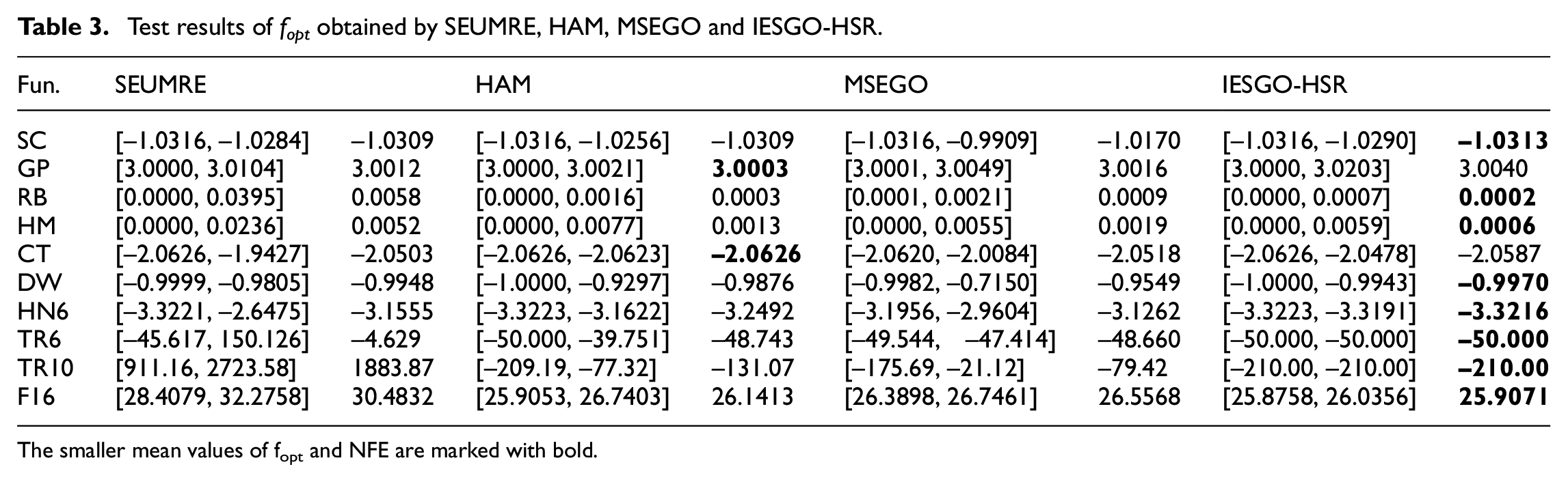
The smaller mean values of fopt and NFE are marked with bold.
Test results of NFE obtained by SEUMRE, HAM, MSEGO and IESGO-HSR.

The smaller mean values of f opt and NFE are marked with bold.
In IESGO-HSR method, the ensemble of surrogates is used to reduce the computational resource. Meanwhile, the hierarchical design space reduction strategy is used to accelerate the search process in a more promising and smaller region. Therefore, the success rate of the proposed optimization approach IESGO-HSR is higher than the comparative methods. From the accuracy, efficiency, and robustness perspectives, the presented IESGO-HSR method shows satisfactory performance. In other words, IESGO-HSR is more efficient, accurate and robust than the other comparative methods for dealing with the complicated BWBUG shape optimization problem.
Numerical model validation
The numerical simulation of the airfoil E186 is carried out to validate the prediction performance of the numerical model XFOIL in this study. The lift coefficient, drag coefficient and LDR are listed in Table 5 and compared with the experimental data gained from the University of Illinois at Urbana-Champaign (UICC). In this work, the lift coefficient C L and drag coefficient C D are normalized as

where ρ indicates the water density, that is, 998.2 kg/m3, S represents the cross sectional area, v means the gliding velocity.
Results of the accuracy validation.
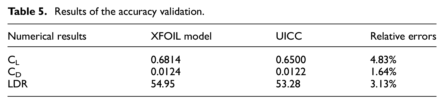
As shown in Table 5, the numerical results obtained by XFOIL model are in good agreement with the experimental data achieved from UIUC. The relative errors from the lift coefficient, drag coefficient, LDR are 4.83%, 1.64%, and 3.13%, separately. It demonstrates that the XFOIL model established in this study can well predict the hydrodynamic performances of the baseline airfoils.
Shape optimization
A couple of optimization methods including SA, GA, SEUMRE, HAM and IESGO-HSR are used to deal with the BWBUG shape optimization problem. In particular, ESGO-HSR method can’t deal with the BWBUG shape optimization problem whereas the actual global minimum is unknown. Therefore, it isn’t selected as the comparative method. In order to reduce the unrepresentative numerical results, ten experiments are executed for these optimization methods. Eight initial sample points are generated using TPSLE and the hydrodynamic performances at these samples are estimated by XFOIL. The search process is iterated till the convergence criterion or terminal criterion (within the limited function evaluations) is contented. The maximum LDR is selected as the optimization target to accomplish the seven sectional airfoils optimization process. Moreover, the inlet velocity of 1m/s and the gliding angle of 7° are applied for each airfoil performance evaluation according to the gliding condition. Table 6 shows the Reynolds number and initial LDR for each baseline airfoil. It’s noticed that the chord length for each baseline airfoil is normalized for clearly analysis. Meanwhile, ε is set to be 0.5 for airfoils XF1, XF2, and 0.01 for baseline airfoils XF3-XF7.
Reynolds number and initial LDR for each baseline airfoil.

The collected ranges and median values of the maximum LDR and NFE for baseline airfoil XF1 with various optimization methods are provided in Table 7, respectively. Similarly, the sign > represents that at least one of the trials could not meet the convergence criterion within 300 function evaluations for optimization methods SEUMRE, HAM, IESGO-HSR and 1000 function evaluations for SA, GA, separately. Moreover, the times of failure searches are recorded in the brackets. The larger values of LDR and smaller values of NFE in Table 7 are marked with bold. As shown in Table 7, IESGO-HSR method has successfully identified the maximum LDR for baseline airfoil XF1 and used the least number of NFE. SEUMRE can also find the satisfied solutions, and its required NFE is larger than that of IESGO-HSR. The HAM method performs unsatisfactory and it fails three times to satisfy the convergence criterion. Moreover, the SA and GA methods require largest NFE than IESGO-HSR, SEUMRE and HAM. The optimal LDR obtained by IESGO-HSR is 57.54, which is 23.53% higher than the initial design. In order to further explain the improvement of maximum LDR obtained by IESGO-HSR, the comparison of shapes between optimal design and initial design is given in Figure 5. As illustrated in Figure 5, the shape changes between optimal design and initial design can be found that: (1) the maximum thickness is increased; (2) the thickness of leading edge is decreased; (3) the reduction rate of the thickness from tail is increased. These changes on the airfoil outline above result in the advancement of the maximum LDR.
Comparison of optimal results for baseline airfoil XF1.

The larger values of LDR and smaller values of NFE are marked with bold.
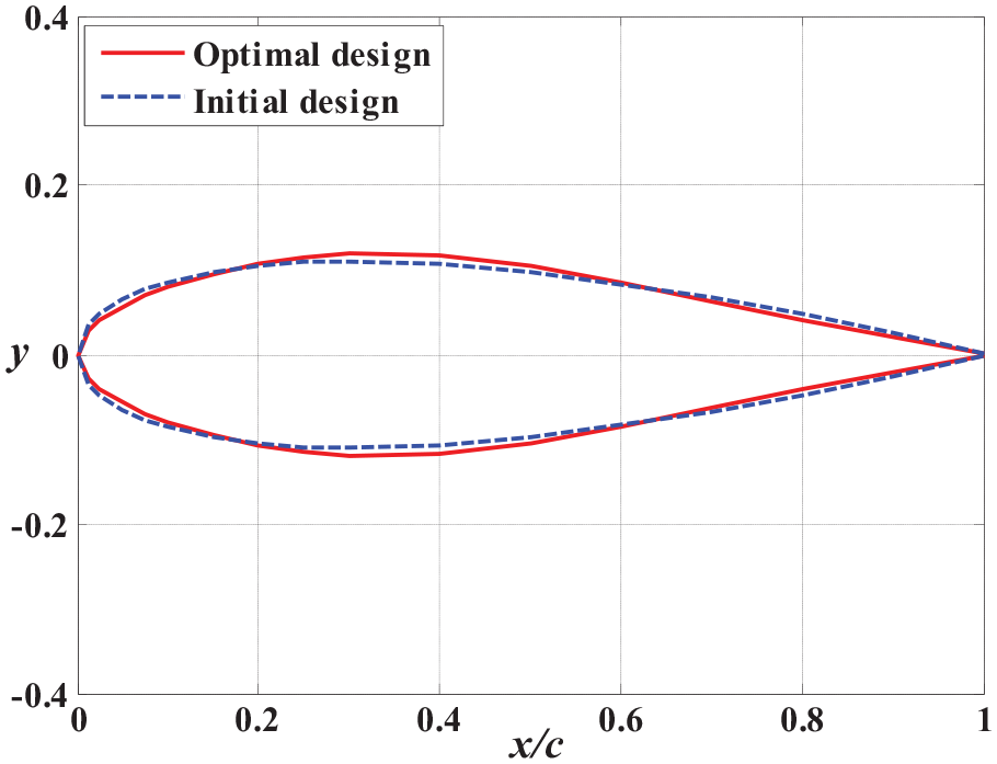
Comparison of shapes between initial design and optimal design.
Similar to the previous case, the other baseline airfoils XF2∼XF7 are also optimized. The statistical results of maximum LDR and NFE with minimum, maximum, and median values are listed in Tables 8 and 9, respectively. The larger values of LDR and smaller values of NFE in Tables 8 and 9 are marked with bold. As shown in Tables 8 and 9, the IESGO-HSR method has successfully found the global optima for all baseline airfoils and used the least number of NFE for all baseline airfoils except for XF4. The SEUMRE method also performs well for all baseline airfoils, but it requires larger NFE than IESGO-HSR. Moreover, as an effective method, HAM performs satisfactory for all baseline airfoils other than XF2 and XF3, and it fails two times on XF2, one time on XF3. The GA method performs terrible for all baseline airfoils, and its required NFE are larger than comparative methods HAM, SEUMRE, and IESGO-HSR. Similarly, the SA method performs worst for all baseline airfoils, and it fails to satisfy the convergence criterion for all baseline airfoils apart from XF2. The optimal results indicate that the hydrodynamic performances of all baseline airfoils are enhanced using the chosen optimization methods. It also demonstrates that the proposed optimization method IESGO-HSR is the reasonable choice with superior performance. Thus, the optimal 3D BWBUG shape can be rebuilt using the optimal baseline airfoils obtained by IESGO-HSR.
Optimal results of maximum LDR for baseline airfoils XF2~XF7.

The larger values of LDR and smaller values of NFE are marked in bold.
Optimal results of NFE for baseline airfoils XF2~XF7.

The larger values of LDR and smaller values of NFE are marked in bold.
Analysis of optimization results
A CFD analysis of the optimal shape and empirical shape is executed to assess the superior performance of the detailed design. The median of optimization results for BWBUG under the given operating conditions are reported in Table 10. The larger values of LDR and improvement, smaller values of NFE in Table 10 are marked with bold. As shown in Table 10, the maximum LDR obtained by optimization methods SA, GA, SEUMRE, HAM and IESGO-HSR is both larger than the LDR of initial design 11.47, which get 17.44%, 18.57%, 19.00%, 23.19%, and 24.32% improvement, separately. Moreover, the LDR obtained by IESGO-HSR method is larger than the comparative optimization methods SA, GA, SEUMRE and HAM. Meanwhile, the required NFE of IESGO-HSR method is least. The maximum LDR obtained by HAM is 14.13, which is 3.52% larger than that of SEUMRE although the required NFE of HAM is large than that of SEUMRE. SA and GA methods perform worst from the accuracy and efficiency perspectives. A visualization of the pressure distribution of the flow around the initial design and optimal design achieved by IESGO-HSR is given in Figure 6. As shown in Figure 6, the initial design and optimal design have an analogical pressure distribution where the low pressure area arises at the leading edge of the upper surface and the high pressure area appears at the nose of the fuselage and the leading edge of the wing in lower surface. It’s noted that the low pressure area at the leading edge of the optimal BWBUG moves backwards compared with the initial BWBUG. Moreover, Figure 7 shows the velocity distributions around the center section of initial design and optimal design. As shown in Figure 7, the center sections of initial design and optimal design have a similar velocity distribution where the high velocity area arises at the leading edge of the upper surface. The high velocity area of the lower surface of the optimal BWBUG moves backwards compared with the initial BWBUG. It both contributes to the improvement of hydrodynamic performance.
Comparison of optimal results for BWBUG.
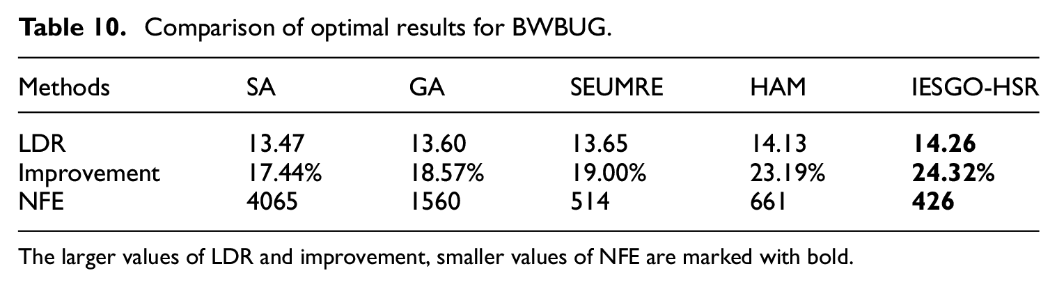
The larger values of LDR and improvement, smaller values of NFE are marked with bold.

Pressure distributions around the initial design and optimal design.
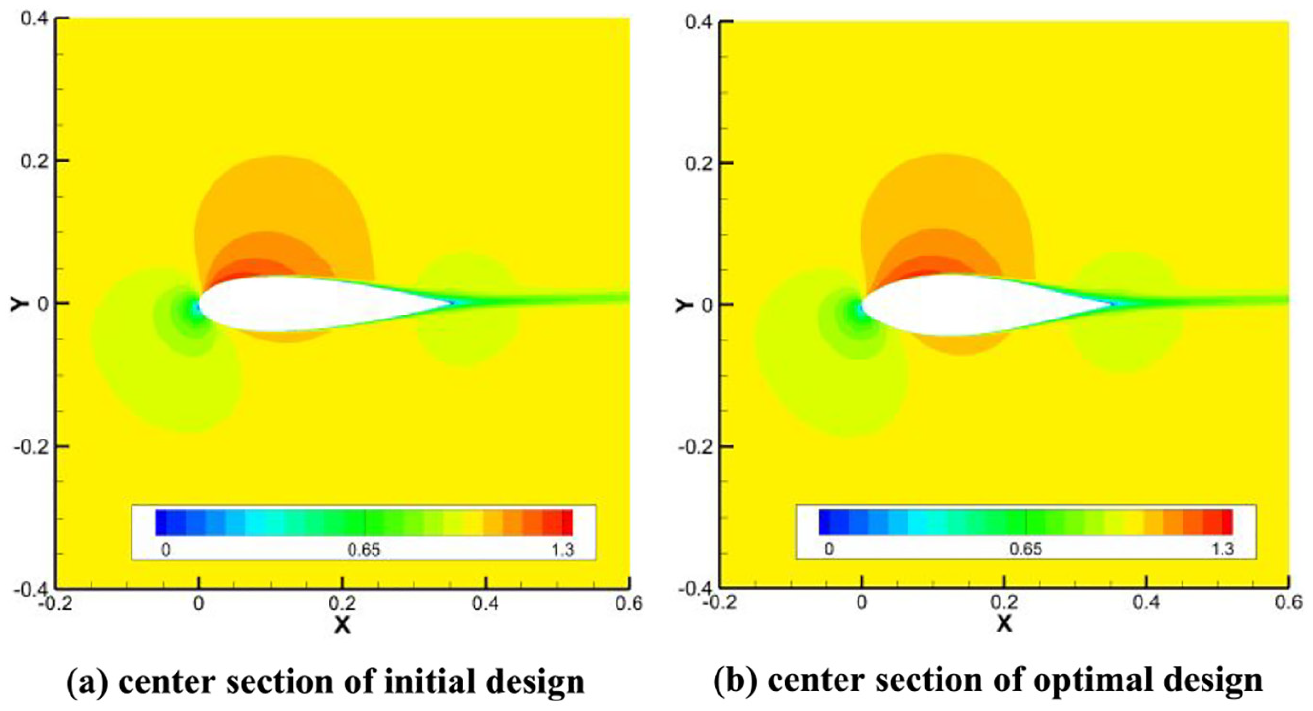
Velocity distributions around the center section of initial design and optimal design.
Table 11 provides the displacement volumes of optimal BWBUG obtained by various optimization methods. The displacement volume of optimal BWBUG obtained by HAM is largest, and IESGO-HSR takes second place. In fact, the displacement volume of optimal BWBUG obtained by IESGO-HSR is 0.00271 m3, which is 2.65% larger than that of the initial BWBUG (the displacement volume of the initial design is 0.00264 m3). The comparison between initial shape and optimal shape obtained by IESGO-HSR is illustrated in Figure 8. It can be discovered that the initial BWBUG has the thinner sectional airfoil at the centerline and the sharper nose. In contrast, the optimal BWBUG has the thicker sectional airfoil at the centerline and the mellower nose that results in a larger loading capacity.
Comparison of displacement volumes for BWBUG.

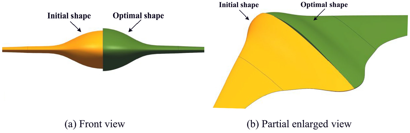
Comparison between initial shape and optimal shape: (a) Front view and (b) Partial enlarged view.
The results show that the presented SBSO framework can well improve the loading capacity and hydrodynamic performance of BWBUG. Moreover, it can significantly reduce the computation time and cost in comparison with the other optimization methods.
Conclusion
A SBSO framework using the CST method and the IESGO-HSR method has been proposed to efficiently deal with the computation-intensive BWBUG shape optimization problem in this work. It aims to further enhance the maximum LDR of BWBUG under the given operating conditions. The main contributions from the proposed SBSO framework are summarized as below
Introduce an improved surrogate-based global optimization method IESGO-HSR that can solve the computationally expensive unknown problems with no need for deep information on their own characteristics.
Introduce a surrogate-based shape optimization framework for BWBUG design. It not only improves the maximum LDR by 24.32% and greatly reduces the computational resource and time during optimization.
It proves that the optimal baseline airfoils get the superior hydrodynamic performances which can keeps the 3D BWBUG shape high gliding efficiency.
Footnotes
Appendix 1: List of benchmark optimization problems
Declaration of conflicting interests
The author(s) declared no potential conflicts of interest with respect to the research, authorship, and/or publication of this article.
Funding
The author(s) disclosed receipt of the following financial support for the research, authorship, and/or publication of this article: Supports from National Natural Science Foundation of China (No. 61803306, 51709229, 51879220), China Postdoctoral Science Foundation (No. 2019M660264), National Key Research and Development Project of China (No. 2016YFC0301300), and the Fundamental Research Funds for the Central Universities (No. 3102019HHZY03009) are greatly acknowledged.