
Abstract
In order to analyze the stiffness characteristics of Assembled Rubber Metal Isolator (ARMI) more accurately, the present work elaborates on the detailed numerical modeling and analysis process of the ARMI, considering prestressing condition. By comparing the applicability of different constitutive models, the reasonable parameters of the proposed Money-Revlon constitutive model were determined by rubber compression test and least square method. Considering the structural characteristics and complex constraints of the isolator, a step-by-step analysis method is described, based on the rigid-flexible coupling theory and the contact cutting algorithm. The full Newton-Raphson algorithm is used to simulate the mechanical behavior of elastic components in ARMI, during the whole compression-torsion deformation process, while the results are verified by theoretical calculation and practical experiments, respectively. For the assembly process, the maximum relative error between numerical results and empirical formulas is 3.97%. The derived torsional curve, under the simulated pre-stress conditions, is in good agreement with the experimental results, and the maximum error is less than 8.43%. The achieved accuracy is significantly improved, compared to the existing simulation model that does not consider the pre-compression process. The proposed approach provides an effective method for the analysis of same type vibration isolator.
Keywords
Introduction
At present, elastic elements are widely used in vibration isolation systems of vibrating machinery, to reduce the transmission of vibration and shock, 1 to reduce noise, 2 and provide elastic recovery force for reciprocating motion.3,4 As an important dynamic component, the stiffness characteristics of the elastic element are directly related to the response of the dynamic system.
Peng Liping proposed an Elastic Compression Bar Modeling method (ECBM), to calculate the transverse stiffness of compression damping spring system. The accuracy of the method is verified by a three-degree-of-freedom (3-dof) dynamic model and a suitable vibration test. 5 Chandravanshi and Mukhopadhyay studied the variations in dynamic behavior of vibratory feeder with different stiffness, using FEM and EMA methods. 6 Gao presented an equation considering the compound pressure of the damper for evaluating the deformation magnitude of the damping springs, in a new 1-dof resonance device, so as to obtain more advanced sports performance. 7
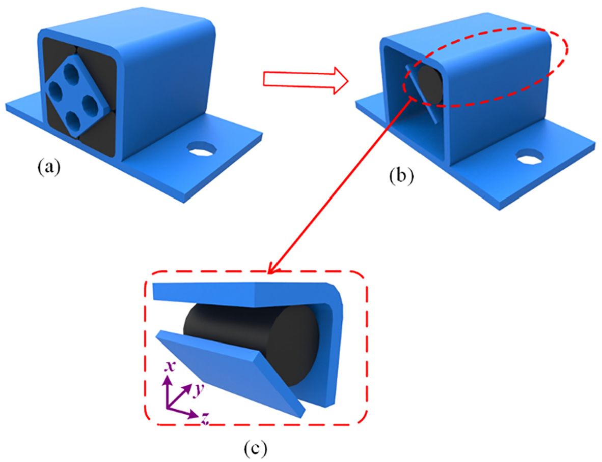
The Assembled Rubber Metal Isolator (ARMI), has achieved good results in the application of the vibrating screen,8–10 because of its good nonlinear elastic mechanical behavior. However, due to the structural characteristics of assembly pre-compression, as shown in Figure 1, the cross section of the rubber rod formed by pre-compressed is difficult to describe with accurate mathematical models, and complex shape deformation under such combined load conditions, it is difficult to calculate the stiffness of ARMI by traditional theoretical approach, but depends more on simulation and test.

ARMI structure diagram.
Wang and Sikora established the finite element simulation model of the metal-elastomer spring, based on Mooney-Rivlin and Bergstrom-Boyce material constitutive model, respectively, but did not consider the pre-compression process of the rubber element.10,11 Experiments show the preload of the compressed rubber will change the stiffness properties. 12 The modeling method without considering pre-compression ignores the pre-load generated by the pre-compression assembly process. Obviously, this will reduce the simulation accuracy of the finite element model. Shangguan et al. proposed a method of using explicit dynamics, to simulate the assembly force required of rubber torsional shock absorber assembly in assembly process, and compared it to the measured values by the sensor. 13
Rubber parts undergo significant deformations, during initial assembly and later, during operation of the spring. The ARMI, studied in this paper, is mainly composed of an outer shell, a flexible rubber rod and an inner square tube. The inner parts are arranged at 45° to the outer shell (Figure 1). The flexible rubber rod is inserted between the inner part and the outer shell, by compression assembly. In particular, the final shape of flexible rubber rod is very complex. The section of the flexible rubber rod changed from round to irregular and difficult to analyze, using general analytical calculation methods.
The difficulty in finite element modeling is that the contact area is not known before solving. Depending on the load, material, boundary conditions and other factors, contact or separation may occur between surfaces, and the state may change suddenly. In order to build an accurate simulation model of ARMI, it is necessary to solve the geometric nonlinear deformation of the pre-compression process of the rubber column and the complexity of contact caused thereby. This study presents a new finite element modeling method for ARMI, under complex pre-deformation conditions. This method fully considers the nonlinearity of rubber material, the geometric nonlinearity, caused by pre-compression during assembly process and the nonlinearity of boundary conditions, under normal operation.
In this paper, section “Hyper-elastic constitutive material model” describes the uniaxial compression experiment of rubber rod and a method to determine constitutive model parameters, by least square method. Section “Modeling and analysis of ARMI using FEM” describes the modeling and analysis process of the ARMI, using FEM technique. Furthermore, the modeling approach for assembly compression nonlinearity and boundary condition nonlinearity of ARMI are presented in sections “Compression assembly process” and “Application of boundary conditions,” respectively. Section “Test equipment for stiffness characteristics of ARIM” describes the experimental test and presents an analysis of the results. The derived conclusions were then used to assess accuracy of the FEM modeling method.
Hyper-elastic constitutive material model
The structure of vibrating screen
The nonlinear elastic properties of the rubber material itself, in order to accurately simulate the mechanical behavior, under large deformation, usually do not alone define the elastic modulus, but use the constitutive model instead, to describe its stress-strain constitutive relation. The constitutive models, commonly used in rubber finite element calculations, include Eo-hookean model, Yeoh model, Mooney-Rivlin model, Arruda-Boyce model, and Vander Waals model.14,15 The selection of the suitable constitutive model of rubber material is directly related to the accuracy of the finite element simulation.
The strain energy density function W can be expressed as a series of strain invariants and principal elongation ratios 16 :

Where, λ i is the principal elongation ratio, λi=1+εi and εi is the principal strain.
The strain energy function of Mooney-Rivlin, Neo-Hookean, and Ogden models is shown in the following formula17,18:

Where, C10, C01, C1, αi, and ui are model material constants.
The principal stress is defined as 19 :

The parameters of rubber constitutive model can be determined by empirical formula or by material test curve fitting.20,21 In general, six types of test methods can be used to completely test the elastic properties of rubber materials: uniaxial tensile, uniaxial compression, isobiaxial tensile, plane tensile (pure shear), simple shear, and volume compression tests. 19 The most important factor in selecting a test method is that the test needs to mimic the actual conditions of use of the rubber component. In order to improve the simulation accuracy, the strain type and range of material test should reflect the actual operational strain of rubber products, as much as possible. Since the bearing deformation of the rubber element, studied in this paper, is mainly about compression deformation, uniaxial compression test is selected, to fit the parameters of the constitutive model.
Uniaxial compression test of cylindrical rubber was carried out, using an electronic universal testing machine. Test devices and specimens are shown in Figure 2(a). The dimensions of the cylindrical sample are: diameter D = 15 mm, initial standard distance L0 = 50 mm. The rubber specimens were placed between the upper and lower disc clamps, for vertical loading, thus reducing friction, as shown in Figure 2(b). There is a very low friction coefficient between the fixture and the rubber end face, which can effectively remove the lateral friction component, on the rubber specimen surface. In the test, the specimen is compressed at a quasi-static rate of 10 mm/min. the specimen is continuously compressed and relaxed for four times, and the last data is taken as the valid data. The experimental force is recorded by the force sensor on the upper part of the crossbeam of the testing machine, and the compression is recorded by the displacement sensor placed inside the crossbeam.

Rubber rod uniaxial compression test. (a) The process of uniaxial compression test of rubber rod. (b) Test size of rubber rod.
In order to minimize the non synchronization of load displacement, caused by Mullins and hysteresis effects, a quasi-static tensile rate was applied to the tensile test, which was replicated three times and the last experimental result was retained.

Where, σEc is the compression stress of rubber, obtained by uniaxial compression test; εEc is the compression strain of rubber, obtained by uniaxial compression test;
Assuming that rubber is an incompressible material, the stress state of uniaxial compression and iso-axial tensile is the same, 22 as the equivalent relationship of stress-strain is:
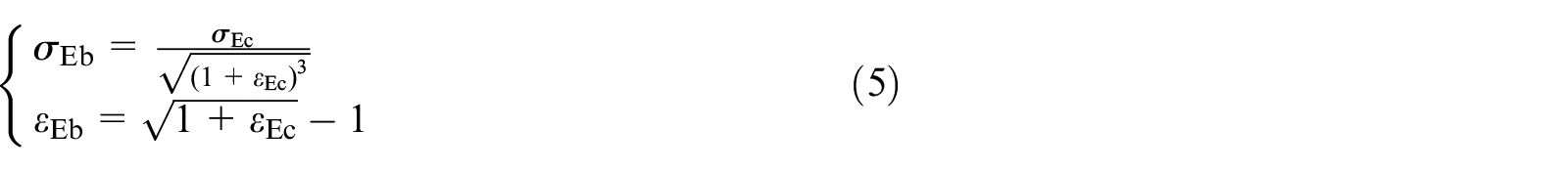
Where, σEb is the equivalent iso-axial tensile stress; εEb is the equivalent iso-axial tensile strain.
In order to fit the experimental data, the relationship between stress and parameters was obtained, by combining (2)–(5), providing a general function expression, as:

Nonlinear Least Square Method is a common method for nonlinear regression. The basis of this method is to approach the model by linear method, and then extract parameters by continuous iteration. The purpose is to make the curve best fit the given data in the sense of least square. According to Nonlinear Least Square Method (NLSM), the model is expressed as:

Where, N is the number of test points for each group of experiments; σi is the stress test value corresponding to the i-th test point;
The fitting effect of the three constitutive models expressed in (2) is determined by using the root-mean-square formula (RMSE):

Using nonlinear optimization method, 23 Model parameters were obtained by solving (7), while the root-mean-square errors, between calculated and experimental values of the three constitutive models, were calculated according to (8), producing the results shown in Table 1.
Fitting parameters and precision of three constitutive models.
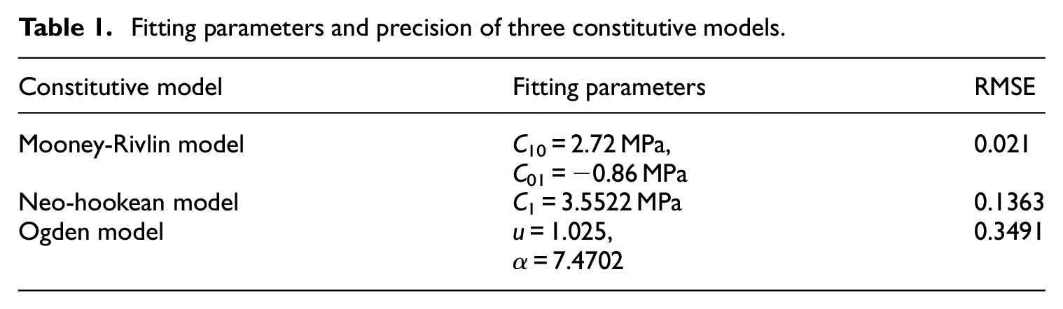
Compared to other models, Mooney-Rivlin model produces the smallest root-mean-square error.
In order to analyze the three constitutive models more directly, Figure 3 shows the stress-strain relation curves of rubber materials, obtained in the test, as well as the fitting results of different constitutive models, where the ordinate coordinate is the logarithmic coordinate.

The stress-strain relation curves of different constitutive models.
It is evident that, the stress-strain relationship of rubber material presents nonlinear characteristics. Under the condition of small strain (εEb < 0.02), the calculated values of the three constitutive models are in good agreement with the test values. With the increase of strain, the error of Neo-hookean and Ogden models gradually increases in which the calculated value of Neo-hookean model is larger than the tested value while the calculated value of Ogden model is smaller. Mooney-Rivlin model fitting better the experimental data, thus describing more accurately the super elastic behavior of the rubber material, under compression strain.
Modeling and analysis of ARMI using FEM
Compression assembly process
According to the structural symmetry, shown in Figure 4(a), 1/4 model can be used for modeling, as shown in Figure 4(b) and (c), to reduce the computational scale. In particular, Figure 4(c) is the state where rubber rod is not assembled.
Entity modeling considering compression. (a) Complete model of ARMI. (b) 1/4 model of ARMI. (c) Preprocessed simplified model of ARMI.
ARMI is a rubber metal assembly composed of metal parts and flexible rubber rod. When it works, inner square tube is twisted relative to outer shell, due to the huge difference in material elasticity, the inner square tube and outer shell perform rigid body rotation, and the flexible rubber rod that is deformed by assembly undergoes further elastic deformation under the action of metal parts. In this way, the rigid body motion and deformation of the flexible body are coupled to each other.
RFCMT 24 is a common method to solve the problem of coupling rigid body motion and elastic deformation in a multi-body combined system. According to the literature, 25 simulations and experiments show that the rigid-flexible coupling model is more accurate than traditional feature-oriented models.
The diagram of RFCMT is shown in the Figure 5. The finite element method is used to separate the flexible body parts into a series of small units, and the units are connected by elastic elements and damping elements. At the same time, the rigid body element is simplified to an equivalent mass point with the same mass properties (including the coordinates of volume, mass, and center of mass) and inertial properties. The rubber surface that comes into contact with metal parts is defined as the contact surface. The connection conditions are constrained through a unified contact interface to realize the displacement of the flexible body surface and the metal rigid body. After the mixed coordinate transformation, the displacement follow-up of the surface of the flexible body and the metal rigid body is realized under the unified contact interface connection conditions.

Diagram of RFCMT.
For ARMI, the metal parts are regarded as an invisible rigid body, while the rubber rod is considered as a flexible body. The physical parameters of the metal parts are set as: E = 2.06e11Pa, Poisson ratio u = 0.33.
The choice of element type directly affects the accuracy of the finite element calculation results. Targe170 and Conta174 are common elements used in contact simulation in ANSYS software. Among them, Targe170 is used to simulate the target surface in 3D, and Conta174 is used to simulate the softer contact surface. Solid186 is a three-dimensional solid element with 20 nodes, with arbitrary spatial anisotropy. The element has the ability of plasticity, super-elasticity, large deformation, and large strain. It can also use mixed mode to simulate completely incompressible hyper-elastic material.26,27
Rubber is simulated as a hyper-elastic unit SOLID186, while the contact area between rubber and metal is simulated by a unit Targe170 and Conta174. For purposes of convenience, regarding the subsequent motion definition, the rotation of the inner component, relative to the shell, is equivalent to the rotation of the shell, relative to the inner component. To this end, Remote points are defined at the shell, as shown in the Figure 6. Finally, the whole system is divided into 2868 units and 7935 nodes.

Model rotation settings.
To simulate the rotation stiffness of ARMI, the method of distributed simulation is adopted. The method of distributed simulation is used to control the load amplitude at the beginning and end of the analysis step, so as to realize the smooth load of the load, which facilitate the calculation convergence. 28
The main calculation process is divided into two parts:
The degrees of freedom in the six directions of the shell and the x-direction of the inner component are restrained; while displacement of 3 mm was applied in the direction of y and z, to simulate the preloading process of ARMI assembly.
On the basis of pre-compression, the deformed state of rubber rod is used as the initial condition. The degrees of freedom, in the six directions of the inner components, are fixed, while the rotation displacement, along z direction, around the center of the inner components, is applied to the shell, simulating the rotation stiffness of ARMI, under working state.
Application of boundary conditions
The analysis of the boundary conditions includes, not only the force boundary and displacement boundary, but also the contact boundary conditions, in the contact area. In the one part of the calculation process, along with the increase of the displacement components in the rubber column, the contact area with the rigid body becomes greater. In addition, in the other part of the calculation process, as the outer shell rotates, the contact area is in a transient state. Due to these conditions, dealing with the problem of rigid boundary between rubber and metal, in the finite element analysis, becomes a complex difficulty. During the assembly process, metal parts and rubber rod are mainly deformed by extrusion, which is a quasi-static process without relative sliding. For this purpose, the contact between rubber, internal components and outer shell is defined as rough contact. Rough contact is a frictional contact without relative sliding. This contact can constrain the tangential movement of the contact surface and ensure that only static friction occurs between two objects without tangential slippage. 29 This ensures that the flexible body and rigid bodies do not generate sliding friction. In addation, this also allow for slight normal separation of the model and thus more accurate simulation of the contact state of the assembly and torsion process.
During the process of rubber compression, due to the deformation of the rubber column, the contact between the inner components and the shell is constantly changing. Therefore, the contact cutting function 30 is adopted, as shown in Figure 7(a). By calculating distance between the nodes of the rigid body surface and the surface of the flexible body, and comparing it with the trim tolerance, the contact state is constantly updated using the contact cutting function. When distance less than trim tolerance, the contact is deemed to have occurred; otherwise, when distance more than trim tolerance, the contact is cancelled. The contrast effect is shown in Figure 7(b). This method can reduce the calculation area in contact calculation, simplify the modeling complexity of the model, and improve the calculation efficiency.

Comparison of mesh cutting before and after deformation of rubber rod. (a) Diagram of contact cutting function method. (b) Actual effect.
Analysis of finite element simulation results
Considering that the Augmented Lagrange Method (ALM) has good convergence in the contact problems of Coulomb friction, large sliding and nonlinear constitutive relations, exhibiting better solution accuracy than that of the pure penalty function method,31,32 it is the indicated proposal for finite element calculation, in this study. Despite the nonlinearity of rubber materials, the convergence of the calculation is ensured, through the adaptation of the Full Newton-Rapson Method (FNRM) of linear approximation with correction. In the iterative process, the node displacement increment criterion is used, to judge the convergence. The solving process of FNRM is as illustrated in Figure 8.

Schematic diagram of calculation flow of FNRM.
The tolerance limit value in Figure 8 is dynamic, which scales with the change of load. Figure 9 shows the convergence curve of the solution process. The whole calculation process has been iterated 178 times, while the convergence curve of each calculation step appears below the collection tolerance curve. Overall, the convergence of process part (2) is better than that of process part (1), which reflects that the non-linearity of the simulation process is mainly concentrated in the compression process represented by process part (1).

The convergence curve of the solution process.
The deformation distribution in the assembly state, as obtained by simulation, is shown in Figure 10, while the illustrations (a)–(f) show the deformation of six respective load steps in this process. Under the loading displacement of 3 mm at the inner assembly, the rubber part is significantly deforming and gradually fills the space between the inner assembly and the shell.
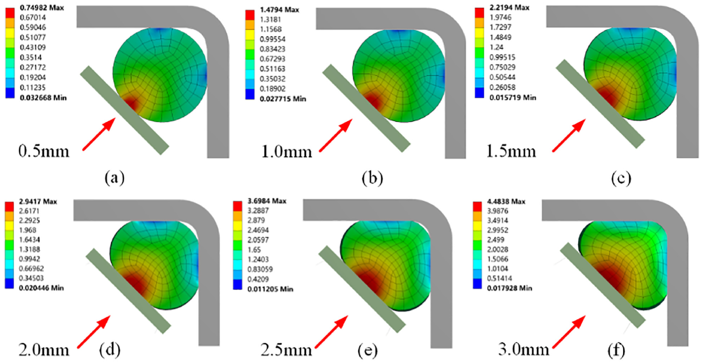
The deformation distribution of assembly progress
In order to verify the simulation results of calculation process part (1), the compression process is considered equivalent to the plane compression problem of rubber rod, as shown in Figure 11. As a qualitative analysis method, the impact of lateral constraints on the reaction force in the main direction during the compression process was ignored. And the empirical formula for the plane compression of rubber rod was used to verify the nonlinear characteristics of the finite element model. Following, the reaction force FRx, FRy, and Fc, in the compression process, can be calculated according to (9).31,33
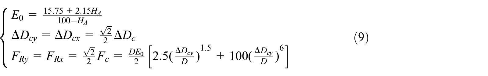
Where HA is the hardness of rubber rod, HA = 88; ΔDc is the compression displacement of rubber column, ΔDc = 3 mm.

Simplified theoretical model of the compression process.
In finite element simulation, the constraint reaction data of rubber column, under compression process, are extracted and compared to the calculated value of the (9). As shown in Figure 12, the theoretical and simulation results exhibit the same trend, which comply with the nonlinear characteristics of the isolator. The maximum relative error is 3.97%, occurring at the compression amount of 0.26 mm. The error is mainly due to the elastic mode scale, adopted by the theoretical model, to describe the mechanical behavior of rubber, which is different from the nonlinear constitutive model used in the simulation.
The lower relative error proves the rationality of the finite element numerical model, which provides the basis for the next step of torsion simulation.

Comparison between approximate theoretical calculation value and simulation value in compression process. (a) Comparison between approximate theoretical calculation value and simulation value. (b) Relative error between theoretical value and simulation value.
Test equipment for stiffness characteristics of ARIM
The deformation distribution, while in torsion state, as obtained by simulation, is shown in Figure 13, where (a) and (f) illustrate the deformation of initial and final state, respectively. Under torsional loading of the external components, with amplitude of 6.28 rad, the whole unit was still in a compressed state, while the contact state and area, between rubber and internal components, was notably changing.

The deformation distribution in torsion state.
In order to verify the validity of torsion simulation results, in calculation process part (2), a test platform was built, according to the requirements of stiffness characteristics test, as shown in Figure14. Test equipment includes CSC88020 test system, ARMI component, displacement sensor, force sensor, and other support equipment.

Test platform of ARIM. (a) The schematic diagram of the test device. (b) Physical chart of the test device. (c) Deformed geometric relationship.
Based on the structure of fixed support platform and ARMI, test tooling was designed, as shown in Figure 14(b). Before the formal test, three pre cycle loading and unloading processes are needed to reduce the influence of Mullins effect and improve the accuracy of test data. 34 During the test, ensure that the displacement load is applied uniformly to meet the working process of ARMI.
The structure and test parameters are shown in Table 2.
Experimental parameters.

Clamping end is fixed on the stable support platform, while other rotating arm end exerts displacement excitation, causing reaction force F, measured by force sensor. During the test, the maximum displacement deformation was set to 14 mm, while the loading rate was set to 1 mm/s.
According to the deformed geometric relationship shown in the Figure 14(c), the relationship between torsion angle and torque M is as follows:

Where, F is reaction force measurement, N. M is reaction torque calculation result, Nmm.
In order to further verify the validity of the modeling methods, used in this paper, a comparison model was established. The 3D entity modeling process was shown in Figure 14. Based on the actual deformation situation shown in Figure 1 and the simulation result shown in Figure 9(f), the shape of the rubber rod was directly defined as an approximate triangular prism shown in Figure 10(f), and was adopted as the initial model of calculation process part (2), while the pre-compression process of rubber column assembly was not considered. The simulation adopted the same parameters, as were used in the processing method, described in section “Application of boundary conditions,” and the final results was shown in the Figure 15.

Entity modeling without considering compression.
Figure 16 shows the torsional stiffness comparison between the simulation model, used in this paper, and the model without pre-compression and the experimental value. The torsional stiffness of ARMI obtained by the two calculation methods is non-linear, that is, the torsional stiffness increases gradually with the increase of the torsional Angle, which corresponds to the experimental trend obtained in. 9 Correspondingly, Figure 17 shows the comparison of the absolute errors as well as relative errors between the two simulation methods and the experimental values. At a torsion angle greater than 0.6°, the model considering pre-compression, as presented in this paper, exhibits a good degree of coincidence with the test stiffness curve, which the maximum absolute error is 284.8 Nmm. As deformation increases, the deviation degree, between the model without considering pre-compression and the test stiffness curve, gradually increases, while the error value reaches 1770 Nmm, at a maximum torsion angle of about 3.6°. However, as the increase degree of torque is larger than the increase degree of absolute error, the relative error tends to decrease gradually. For the model without considering pre-compression, the maximum relative error occurred at 0.6°, where the stiffness value changes nonlinearly, up to 59.4%. And compared with it is that the maximum relative error of model considering pre-compression occurs at 0.12°, and is 8.43%. Obviously, the nonlinear characteristics of ARMI can be accurately fitted.

Comparison of torques of different models and experimental values.
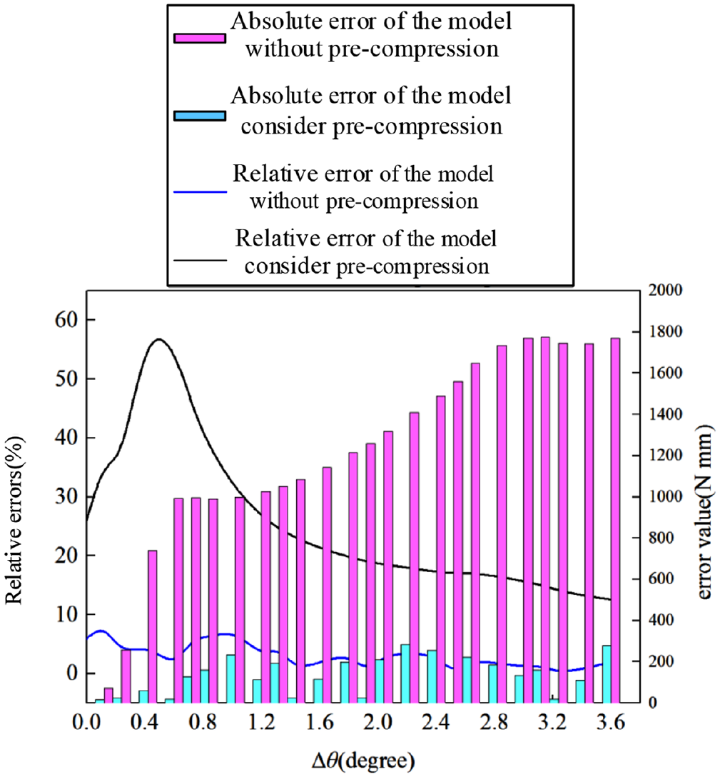
Comparison of absolute errors and relative errors of different models and experimental values.
It is proven that the method, used in this paper, is in very good agreement with the experimental value, while it can better reflect the nonlinear characteristics of ARMI stiffness components. Admittedly, the accuracy of the result is higher than that of the model without pre-compression consideration.
Conclusion
A finite element modeling method of ARMI isolator, based on rigid-flexible coupling, is proposed. The method fully considers the nonlinearity of rubber material, the geometric nonlinearity of pre-compression process and the nonlinearity of boundary conditions. Nonlinear least squares fitting method and real experiment were used to determine the parameters of the elastic component nonlinear constitutive model. Geometric nonlinearity and contact nonlinearity, in assembly compression process, were simulated by contact cutting. The maximum relative error with the empirical formula is 3.97%, which verifies the rationality of the numerical model established according to the method of this paper and the simulation accuracy of the compression process, where the practicability and applicability of the modeling technology of rubber material super elastic constitutive equation and the effectiveness of the proposed finite element simulation method were verified.
An ARMI torque test device measuring ARMI torque approximately based on linear motion was designed, and the relative errors between experimental values and the simulation values under the conditions of pre-compression and non-pre-compression are compared. The model considering pre-compression established in this paper significantly improves the simulation accuracy of the torsion process, and the maximum relative error with the experimental value is 8.43%.
The modeling method, proposed in this paper, can accurately reflect the nonlinear characteristics of ARMI, while it is a guide of great significance for the stiffness prediction and vibration analysis of similar structures.
Footnotes
Declaration of conflicting interests
The author(s) declared no potential conflicts of interest with respect to the research, authorship, and/or publication of this article.
Funding
The author(s) disclosed receipt of the following financial support for the research, authorship, and/or publication of this article: Financial support for this work, provided by the National Natural Science Foundation of China (Project No. 51775544, No. U1508210), Natural Science Foundation of Shandong Province (Grant No. ZR2019PEE024), High-Level Talents Research Project of Linyi University (Grant No. LYDX2019BS010), Natural Science Foundation of the Jiangsu Higher Education Institutions of China [19KJD440002], and the Project Funded by the Priority Academic Program Development of Jiangsu Higher Education Institutions (PAPD), are gratefully acknowledged.