
Abstract
The aim of this article mainly lies in two aspects. The first is to investigate the effect of inlet swirl distortion on the performance and stability of a low-speed compressor experimentally. The second is to quantify swirl pattern revolution through the compressor and find out background causes of the change in compressor performance. Swirl distortion makes the leading-edge incidence opposite between tip and hub regions, compared to that of clean flow. And the compressor performance change is ultimately determined by these two aspects. Results indicate that negative bulk swirl improves pressure rise, and the effect is on the contrary to the positive bulk swirl. Under the condition of paired swirl, pressure rise also presents a reduction. All these three types of swirl have little effect on the stall boundary. Although swirl distortion shows clear recovery at rotor exit, downstream components still work at off-design conditions due to the induced nonuniformity in axial velocity and total pressure.
Introduction
Generally, there are four types of inlet distortions: total pressure distortion, total temperature distortion, planar waves, and swirl distortions. 1 In the earlier period, aircraft engines were equipped with straight intake systems, in which condition the total pressure distortion has the dominant effect. With the more urgent need of stealth for military aircraft, highly offset intakes are adopted more widely, which brings about various swirl distortions at compressors inlet. And in 2009, NASA launched the “Environmentally Responsible Aviation” project, aiming at reducing noise, emissions, and fuel burn. One of the several promising technologies NASA has put forward is the concept of highly integrated aircraft architecture.2,3 Despite many significant benefits for this concept, the issue of coupled total pressure and swirl distortion arises. Catastrophic consequences may occur if the capability of compressors to resist inlet swirl distortion is overestimated at the design step.
Inlet swirl gets increasingly more concerns since twin turbofan engine fighter, Tornado, encountered a serious compatibility problem between the intake system and the compressor. To describe the property of swirl distortion, three swirl descriptors, that is, swirl intensity, swirl direction, and swirl pair, were proposed by Bouldin and Sheoran 4 and were then adopted by SAE International to quantify the loss of compressor stability and pressure ratio. 5 A representative value of swirl intensity caused by serpentine intake ducts is up to the range between 6° and 13°. 6 Some experimental work indicated inlet swirl deteriorated compressor performance and stability, 7 and further caused an increase in fuel consumption and a decrease in thrust. 8 Many different-level numerical simulations were also conducted to investigate the effects of swirl distortions on compressor performance through 1-D, parallel compressor and 3-D compressor simulation.7,9–11 Young et al. 12 and Eck et al. 13 found that with the compressor throttled to the stall boundary, casing static pressure irregularity presents an increasing trend, and once a certain threshold was reached, the compressor was stalled. The varying blade loading around the circumference due to the change in the incidence caused by swirl distortion changes compressor stability accordingly.
The objective of this article is to investigate the swirl revolution across the compressor and the corresponding effect on the compressor. The arrangement of the article is as follows. In the “Experiment methodology” section, the test rig and measurement methods are presented. In the “Results and analysis” section, the interaction between the inlet swirl and compressor is discussed. Finally, conclusions are drawn based on the experiment results.
Experimental methodology
Experiments were conducted on a low-speed two-stage axial compressor without inlet guide vanes (IGVs), which enables the compressor to interact with swirl distortion straightforwardly. The structure of the facility is shown in Figure 1. The compressor is driven by a 200-kW motor, energy of which is from the power. A torque meter is also equipped to measure the torque and rotational speed for the calculation of compressor efficiency. The operation condition of the compressor is adjusted through the valve, and a silencing power is installed at the exit of the outlet duct to reduce exhausting noise. Table 1 lists some necessary geometry and aerodynamic specifications of the compressor. The rotating direction of the compressor is clockwise (looking downstream). To create the specified swirl distortions, a blade-type swirl distortion generator (BSDG) was adopted. Previous numerical work by Tu et al. 14 indicated that paired swirl can be created through two sets of blades with opposite stagger angle (Figure 2(a)); if one set of blades is removed, negative/positive bulk can be generated (Figure 2(b)). As illustrated in Figure 1, BSDG is installed at double casing diameter upstream of the rotor blade leading edge and three measurement sections are labeled as Sections 1, 2, and 3. Section 1 is set at about 1 casing diameter downstream of the BSDG. Section 2 is one chord upstream of the rotor blade leading edge, and Section 3 is just immediately downstream of the rotor blade.
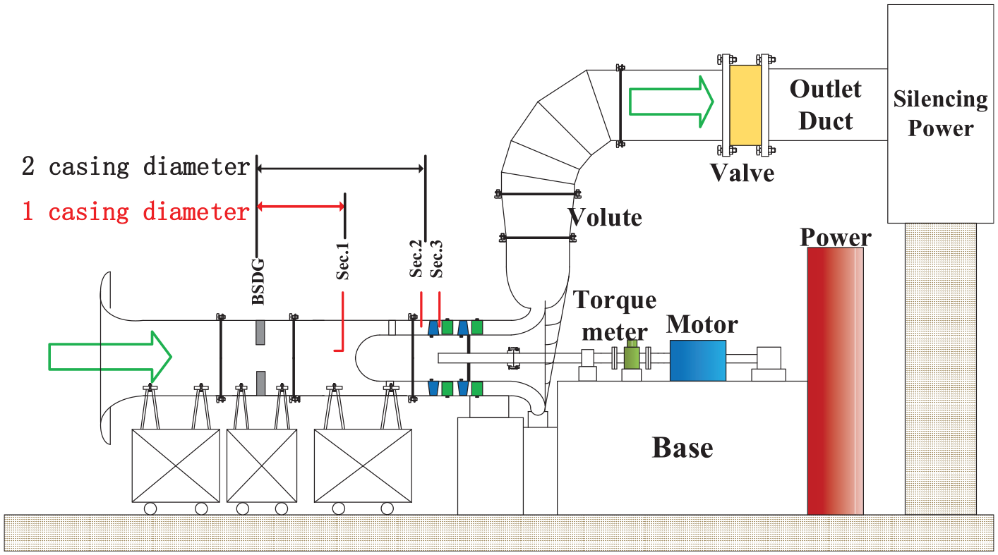
General schematic drawing of the test rig.
Some necessary specifications of the compressor.

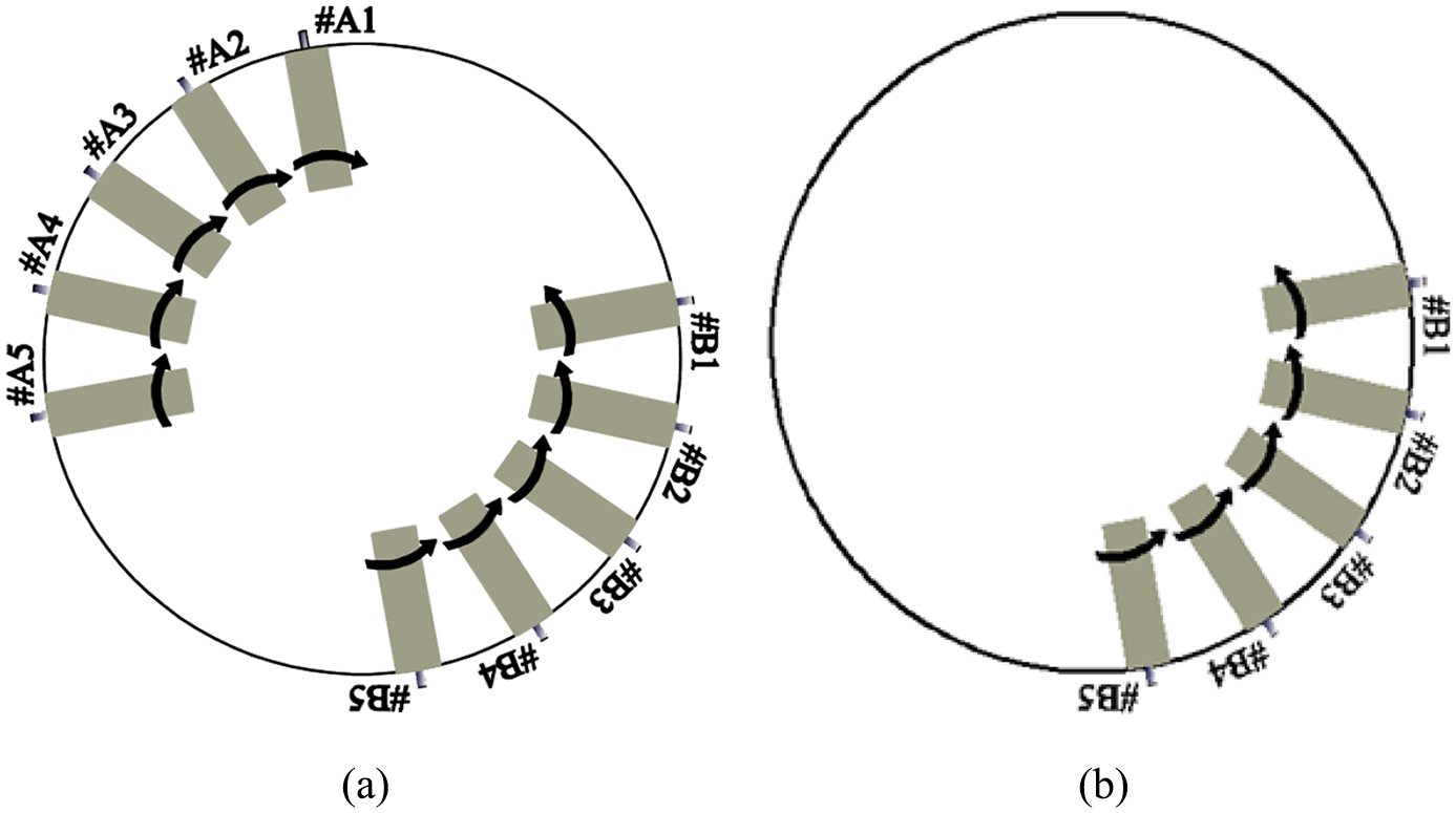
Blades distribution for different swirl distortions: (a) for the paired swirl and (b) for the bulk swirl.
Figure 3 presents the main adopted probes in this article and the corresponding measuring grid distributions. Total pressure rakes were employed to acquire the overall performance of the compressor. There are six rakes at the compressor inlet, evenly distributed circumferentially, and eight for the outlet.

Photographs for the adopted pneumatic probes and the corresponding measuring grid distributions.
The calibration and data reduction of the four-/five-hole probes resemble those in the work by Johansen et al. 15 For the sake of high spatial resolution, the BSDG was installed in a rotating device (Figure 4). Through the relative circumferential motion between the BSDG and pneumatic probes, full-annular flow fields can be captured. Based on the wind tunnel test, the uncertainty in the tangential flow angle is within the range of ±0.3° and the velocity is within the range of ±0.6 m/s. According to the method of error estimation by Johansen et al., 15 the error of relative flow angle is within the range of ±0.5°. At Section 1, there are 20 measurement rings, and that at Sections 2 and 3 is 10. All three axial sections share the common resolution in the circumferential direction, that is, all measured at every 6°. Experiments were conducted at the rotational speed of 800 r/min (about 53% design value).

Photograph and brief CAD model of the rotating device.
Results and analysis
Swirl patterns at three axial sections were measured at the flow coefficient of 0.8, labeled with a pentacle in Figure 5. At the outset, it is essential to state that throughout the whole article, all the presented parameters related to Sections 2 and 3 were subtracted by that of clean flow to isolate the effect of swirl distortions. The radial profile of tangential flow angle under the condition of clean flow at Sections 2 and 3 are presented as an example in Figure 6.

Performance curve under the clean flow and the operation condition for the measuring of swirl pattern.

Radial profiles of tangential flow angle at Sections 2 and 3 under the condition of clean flow.
Swirl pattern revolution
The plots of tangential flow angle contours combined with streamlines for paired swirl and bulk swirl at Section 1 are shown in Figure 7. Apparently, the specified paired swirl and negative bulk swirl were created. For the paired swirl, both co-rotating and counter-rotating parts occupy the region of 180° annulus, respectively. For the bulk swirl, the counter-rotating swirl only occupies the half annulus. Notably, the tangential flow angle of inner and outer rings is adverse. It means when the flow reaches the inlet of the compressor, the tip and hub regions of rotor blades work at opposite off-design conditions. A large radial flow angle, demonstrated in Figure 8, may affect spanwise migration in blade passage. It also can be deduced that if the blades were replaced with those of set A (in Figure 2), co-rotating bulk swirl would be generated.

Combination of tangential flow angle contour and streamlines at Section 1: (a) for paired swirl and (b) right for negative bulk swirl.

Radial flow angle contour at Section 1: (a) for paired swirl and (b) for negative bulk swirl.
When arriving at Section 2, paired swirl still persists but the intensity was attenuated remarkably (as indicated in Figure 9(a)). Due to the nonuniformity in the absolute tangential flow angle, rotor blade leading edge incidence varies remarkably (as indicated in Figure 9(b)), which will affect compressor performance significantly. Comparing Figures 10 and 8, the radial flow angle is almost completely restrained after the function of rotor blades, relieving downstream components from severe radial migration. The relative tangential flow angle contours for three types of swirl distortion, presented in Figure 11, show tiny deviations within the range of ±2°. The quantitative relation between relative and absolute tangential angle is shown in equation (1)


Flow parameter contours at Section 2 under the condition of paired swirl: (a) for tangential flow angle and (b) for incidence.
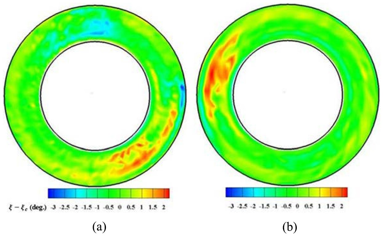
Radial flow angle contours at Section 3: (a) for paired swirl and (b) for negative bulk swirl.

Relative tangential flow angle contours at Section 3: (a) for paired swirl, (b) for negative bulk swirl, and (c) for positive bulk swirl.
Despite the slight difference in relative tangential flow angle at rotor exit, the induced nonuniformity in axial velocity (as indicated in Figure 12) makes the swirl distortion still exist (shown in Figure 13).

Normalized axial velocity contour at Section 3: (a) for paired swirl, (b) for negative bulk swirl, and (c) for positive bulk swirl.
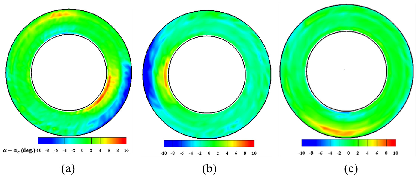
Absolute tangential flow angle contours at Section 3: (a) for paired swirl, (b) for negative bulk swirl, and (c) for positive bulk swirl.
The combination of the nonuniformity in axial velocity (i.e. mass flux) and tangential flow angle determines the overall work input from rotor blades to airflow. With the interpretation of velocity triangle in Figure 14, the counter-rotating swirl goes through greater turning in the rotor passage, increasing the loading, and vice versa for the co-rotating swirl. Figure 15 presents the radial profile of the mass-averaged normalized total pressure. Combining the axial velocity and tangential flow angle contours for the negative bulk swirl (Figure 12(b) and 13(b)), the negative tangential flow angle (prone to increasing the loading) region at tip exactly corresponds to the region with large axial velocity, and the situation is adverse for the hub region. Hence, the tip region produces higher pressure rise, and the hub region produces lower pressure rise. The situation is contrary for the positive bulk swirl. With respect to the paired swirl, the condition is determined by the compromise between these two opposite swirls. From the similarity of radial profile between paired swirl and negative bulk swirl in Figure 15, it can be concluded that the counter-rotating part of the paired swirl plays a dominant role.
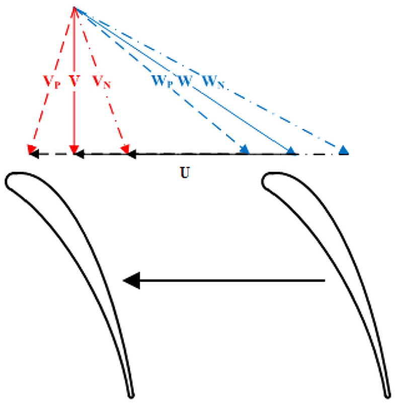
Velocity diagram upstream of the rotor leading edge.
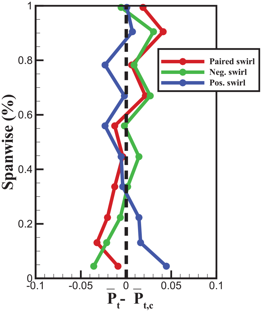
Radial profiles of mass-averaged normalized total pressure at Section 3.
Comparing the tangential flow angle contours between Sections 3 and 1, it can be found that due to the decay in the duct and through the function of cowling and rotor blades, swirl distortions were attenuated remarkably. Despite that, swirl distortions still exist and propagate downstream, making the downstream components exposed to swirl distortions. In order to quantitatively describe the revolution of swirl, the descriptors of

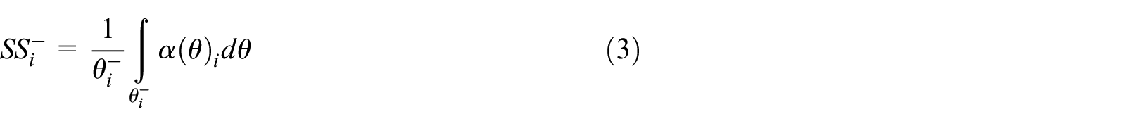
where

Radial distribution of
Overall performance
Figure 17 presents the overall performance map under the clean inlet flow, paired swirl, and positive/negative bulk swirl. Due to the combined effect of greater exhaustion loss at larger mass flow condition and lower pressure ratio at partial rotational speed (about 53% designed speed), the operation range is narrow. The effect of all these three types of swirl distortion on the stall boundary is nearly negligible. However, the effect on the pressure rise is evident.

Overall performance map of the compressor under different inlet flow conditions.
For the positive bulk swirl, it decreases the pressure rise in general. However, the effect becomes increasingly negligible with the working point going from the maximum pressure rise to stall boundary. For the negative bulk swirl, it increases the pressure rise for the operation range of mass flow larger than that of the maximum pressure rise. After the maximum pressure rise, it decreases the pressure rise inversely. As stated before, the work input from rotor blades to airflow is determined by the combination of tangential flow angle and mass flow. For the positive bulk swirl, the co-rotating swirl is at the tip region, prone to decreasing total pressure, and the counter-rotating swirl is at the hub region, prone to increasing total pressure. Despite the lower axial velocity at the tip region and higher axial velocity at the hub region, the region area is much more for the positive swirl at outer rings than that of the negative swirl at inner rings. Ultimately, the result is determined by the co-rotating swirl in the tip region. The interpretation is also applied to the negative bulk swirl. With respect to the decrease in pressure rise for the negative bulk swirl over the maximum pressure rise, it owes to additional loss due to overturning by the counter-rotating swirl at tip region. The increasingly negligible effect of the positive bulk swirl in decreasing pressure rise may attribute to the relief of the overturning by the co-rotating swirl at tip region. The phenomenon shares a similarity with the numerical research of Davis et al., 9 where near the stalling flow rates, the pressure ratio under the condition of positive/negative bulk swirl approaches to the values of clean flow.
Summaries
To understand the interaction between inlet swirl distortions and axial compressors, an experimental investigation was conducted on a two-stage, low-speed axial compressor. The total-to-total pressure rise of the compressor was acquired to analyze the effect of different types of inlet swirl distortions. Highly spatial resolution measurements were also conducted at three axial sections to investigate the swirl pattern revolution through the compressor and to find background causes in the change of the compressor characteristics.
On the one hand, the radial component in the swirl pattern is nearly eliminated at the outlet of the first-stage rotor, relieving the downstream components from severe radial migration. On the other hand, total pressure distortion was generated at the rotor exit as a result of inlet swirl distortion, deteriorating the performance of downstream components further. The intensity of swirl distortions was attenuated by more than 50% but far from completely eliminated due to the induced nonuniformity in axial velocity.
Generally speaking, all three types of investigated swirl distortion has a negligible effect on the compressor stability, but the impact on pressure is evident. Negative bulk is of benefit for the pressure rise and the effect is on the contrary for the positive bulk swirl. The decrease in pressure rise under the condition of paired swirl indicates the co-rotating part in the paired swirl plays a dominant role. It is also essential to mention that the above conclusions may only be applicable to this low-speed axial compressor, and the situation could be different for high-speed compressors.
Footnotes
Appendix
Declaration of conflicting interests
The author(s) declared no potential conflicts of interest with respect to the research, authorship, and/or publication of this article.
Funding
The author(s) disclosed receipt of the following financial support for the research, authorship, and/or publication of this article: The research was funded by the National Science and Technology Major Project (grant no. 2017-II-0004-0017).