
Abstract
Accurate and real-time position of preview point is significant to trajectory tracking control of vision-guided intelligent vehicle. The unavoidable delay of road automatic identification system weakens trajectory tracking control performance, and even deteriorates the vehicle stability. Therefore, a compensator for the delay of road automatic identification system was proposed which combines the current statistical model and adaptive Kalman predictor to estimate the state of preview point position. The trajectory tracking sliding mode controller of intelligent vehicle is established through a 2–degrees of freedom vehicle dynamic model and motion model by using MATLAB/Simulink and CarSim. The trajectory tracking performance under 20–100 ms delay is analyzed. The simulation results show that the trajectory tracking performance of intelligent vehicle will be affected by the delay of road automatic identification system, reducing tracking accuracy. And when the delay is too large, it will deteriorate the vehicle stability and safety. In addition, the simulation results also verify the effectiveness of current statistical–adaptive Kalman predictor compensator at different delays.
Keywords
Introduction
Intelligent vehicle (IV) is an important part of intelligent transportation system (ITS),1–3 which is carried with advanced vehicular sensors, controllers, and actuators and combined with modern communication and network technology. It is equipped to conduct road environment perception, 4 path planning, 5 and automatic control. 6 IVs can reduce traffic accidents, improve road commuting efficiency, and save energy. The research on trajectory tracking motion control remains as a key project of IVs and has been widely concerned by scholars.
The research of trajectory tracking mainly focuses on the uncertainties and external disturbances of IV models. In order to solve these problems, scholars have proposed many control strategies, such as PID (proportional integral derivative) control, 7 adaptive control, 8 fuzzy control, 9 optimal control, 7 linear matrix inequality control (LMI), 10 robust H∞ control, 11 sliding mode control, 12 output feedback control, 13 model predictive control (MPC), 14 feedforward and feedback control, 15 and so on. Road automatic identification system (RAIS) of vision-guided IV can collect real-time image of road ahead, and obtains the position deviation of vehicle relative to the target path at the preview point. The image acquisition of road ahead is usually accomplished with CCD (charge-coupled device) camera.16,17 With the development of intelligent and networked vehicles, the research of vehicle motion control with delay in data transmission becomes more and more important. Motion control system of IVs is mostly based on network control system (NCS). Therefore, the delay of RAIS can be composed of two parts: lane detection delay (internal delay of communication nodes) and network transmission delay. 18 Lane detection is a complex process, generally including image acquisition, gauss smoothing filter, edge detection, vanishing point detection, line detection, model matching, and trajectory tracking. 19 Lane detection speed is determined by image quality, image processing algorithm, and hardware processing speed. The low sampling rate and noticeable delay are major problems for most of vision sensors.20,21 Although using high performance hardware can improve processing speed, such systems are usually too expensive for industrial applications. 22 The real-time data of vehicle motion controller and RAIS are interacted by CAN. Due to the limitation of network bandwidth, interference from environmental factors, physical link damage, and other factors, communication delay and interruption are unavoidable, which will have a significant impact on vehicle safety and comfort, resulting in vehicle performance degradation, or even out of control. 23 In practical control applications, it is often difficult and unnecessary to calculate each component of communication delay accurately, but usually around its statistical behavior and experimental results. The results of the research hold valuable and significant references for the application of CAN bus in real-time systems. 24
In summary, there are usually some unavoidable delay in the RAIS. The controller receives the delayed signal and then controls the actuator to track the target path. It is likely to reduce the tracking accuracy of the vehicle trajectory. In severe cases, it will even destroy the system stability. One of the key problems in IV motion control is to ensure the trajectory tracking accuracy while considering the RAIS delay. For control systems with delays, there are some well-studied theoretical research achievement, which can provide some useful enlightenment at present. Wang et al. 25 present a maneuvering model algorithm to solve the uncertainty of vehicle motion in the vehicle active collision avoidance alarm system. In Guo et al., 26 combining vector field histogram method and Kalman prediction algorithm, a hybrid obstacle avoidance algorithm is proposed. The Kalman predictor predicts the optimal location of dynamic obstacles at the next moment to solve the obstacle avoidance problem in the uncertain environment of IVs. In Oyama and Nonaka, 27 a time-delay compensation method based on Smith predictor is proposed, which converts the time delay into state delay, and achieves stable path tracking for non-holonomic vehicles with time delay. In Dragolj et al., 28 in order to reduce the impact of delay in NCSs, improved control strategies of Smith predictive controller and parallel fuzzy PI (proportional integral) controller are proposed, respectively. In Wang et al., 29 to reduce the data transmission delay and dropout in the control system of autonomous ground vehicles, a robust H∞ state feedback controller is proposed. In Shin and Yi, 30 a wireless communication delay compensation for integrated risk management of automatic vehicles is proposed. A state augmented estimation algorithm of extended Kalman filters (EKFs) is proposed to compensate the communication delay. In Liu et al., 22 a robust H∞-based LQR algorithm is proposed to solve the problem of sensor-induced delay. In Tao et al., 31 a compensation method is proposed to compensate the adverse effect of tracking sensor delay on the accuracy and stability of servo system. According to the delayed tracking sensor signals, the current target position and velocity signals are calculated by Kalman predictive filtering, and the two signals are used as position guidance signals and speed feed-forward signals of servo system, respectively, for closed-loop. In Guan et al., 32 a compensator is designed based on the current statistical (CS) model in the theory of maneuvering target tracking to compensate the transmission delay of the vision system of vehicle driving simulator. In Zakaria et al., 33 a method of calculating lateral error of UVA based on predictive control algorithm is proposed to improve the performance of trajectory tracking. Although the theory of maneuvering target tracking originated from aerospace, it has been widely used in the prediction of the trajectory of IV. The delay of RAIS problem in IV path tracking control can be treated as the delay problem of maneuvering target tracking.34,35 The adaptive Kalman filter algorithm can predict the state of the signal at a future time. It is a common compensation method for target tracking delay. The “current statistical (CS)” model is a classical statistical model of maneuvering target, combined with adaptive Kalman predictor (AKP) for delay compensation. The predictive signal of the future time is used as the input of the controller, so that the delay disturbance can be eliminated.
In this work, a compensator by using the CS model and AKP is presented. The aim of the proposed compensator is to predict position of preview point in the road ahead, and improve the tracking accuracy and driving stability. The contributions of this article are as follows: (1) The inevitable delay of RAIS is considered in the trajectory tracking model, and a generalized delay form is presented and (2) the trajectory tracking model combined with vehicle lateral dynamics is established to make the vehicle track the desired path and improve the vehicle stability.
The remaining part of the article is organized as follows. The “Modeling and problems” section models the vehicle dynamics, trajectory tracking, vehicle–road, and RAIS delay. The proposed CS-AKP compensator is presented in the section “Design of CS-AKP compensator.” In the section “Simulation results,” simulation based on the MATLAB/Simulink–CarSim joint platform is presented, and the results are analyzed. Finally, the “Conclusion” section summarizes the article and gives an outlook for future work.
Modeling and problems
To intuitively analyze the influence of the delay of RAIS on the trajectory tracking of IVs and facilitate the comparative analysis of the compensation performance of delay compensator, an IV simulation system including vehicle dynamics model, trajectory tracking model, and vehicle–road model was established as shown in Figure 1. In the red dotted line frame is the trajectory tracking controller, which consists of expected yaw rate generator and sliding mode controller. The RAIS system can identify and update the lane lines in front of the vehicle in real time, and outputs the relative position of preview point. The expected yaw rate generator generates the expected rate

Control system flowchart.
Dynamics model of IV
Figure 2 shows the schematic diagram of the 2-DOF (degrees of freedom) vehicle model in lateral and yaw directions. Assuming the front wheel angle is small. The pitch, roll, vertical motions, and the suspension system of the vehicle are ignored. The lateral dynamics equations of the vehicle can be deduced that

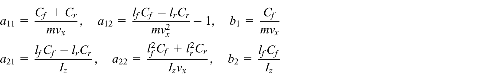
where

where

Because the sideslip angle

with

The schematic diagram of IV’s dynamic model.
Vehicle–road model
The position deviation and heading deviation between vehicle and lane need to be converted from camera coordinate system, vehicle coordinate system, and road coordinate system. 16 In the simulation experiment of vehicle lateral motion controller, the relative position between vehicle and road should be obtained according to the transformation relationship between vehicle local coordinate system and road coordinate system. The real-time position and heading of the vehicle in the local coordinate system are shown in Figure 3.
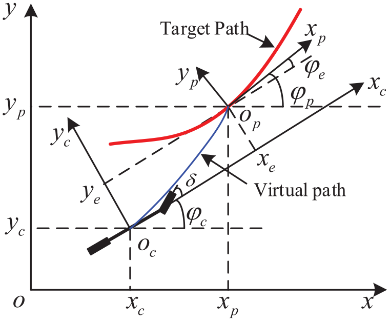
Schematic diagram of preview trajectory tracking method.
At some point, the position coordinate of the vehicle center of mass in the global coordinate system (shown in Figure 3) is

As shown in Figure 3, the center of mass of vehicle is

where
In formula (5), the motion position of the vehicle is determined by yaw rate
In the local coordinate system
The virtual driving trajectory equation is shown as follows

Virtual driving trajectory should meet the requirements provided in equation (8)

where
Combining equation (7) with equation (8), we can obtain the equation of planning curve

Assuming the vehicle tracks the target trajectory steadily without deviation, the curve equation of the target trajectory is
The curvature

The first derivative of curvature is

where s is the vehicle trajectory, then the yaw rate

According to equations (10)–(12), the change of

Combining equation (9) with equation (13), the yaw rate variation of approaching the target trajectory along the virtual trajectory is expressed as

The expected yaw rate is shown in equation (15)

where
Sliding mode control design
There are some complex nonlinear factors existing in the IV which means that it is hard to achieve the tracking accuracy requirements, and sliding mode control is a practical alternative for a variety of motion control applications, especially to accurate mathematical models, thanks to its simple control algorithm, high robust, and reliability. 36 The working principle of the sliding mode controller is shown as follows:
To reduce the influence of unmodeled system and uncertainties of vehicle parameters on the lateral controller, a sliding mode controller is designed based on 2-DOF vehicle dynamics model to track the expected yaw rate. The sliding mode switching surface is defined as

where

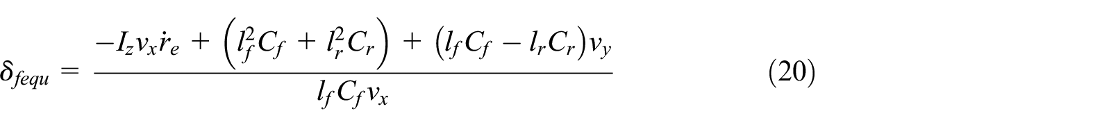
Combining equation (17) with the vehicle dynamics model, we can get

If the sliding surface approaches zero with exponential approaching velocity, the output of the sliding mode controller is

Make sure the system is close to the ideal sliding surface when the system is not on the sliding surface, we have

Finding the first derivative of equation (21),

To weaken the chattering of the system around the sliding surface, saturation function
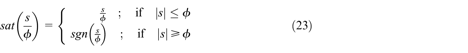
where
Time delay of RAIS
The real-time front road state can be obtained by CCD camera in the RAIS, and the lateral deviation
With the time delay induced, the ideal condition under which equation (7) is derived is no longer satisfied. The influence of delays on vehicle dynamics control can be explained in Figure 4. Because the input signal of the vehicle controller is delayed by RAIS, the input of the vehicle control at time t can be written as

where

Effect of delays on vehicle dynamics control.
Note that in practice, the delay of RAIS is a time variable, the maximum delay can be expressed as
To overcome the influence of delay disturbance on trajectory tracking performance of IV, it is necessary to predict the future state of the vehicle according to the past and present state vector of IV, the deviation of vehicle position, speed, acceleration, and vehicle dynamics model. This means the current data received by the controller input are incorrect, and then the vehicle motion is controlled by using the future state parameters to compensate the delay. Thus, the current state of input is predicted by the current and past state parameters of delay state.
Design of CS-AKP compensator
CS model
According to the previous section, the delay of RAIS ultimately leads to poor tracking performance of preview point, which belongs to the category of maneuvering target tracking. The CS model 37 is a typical maneuvering model, which is widely used in maneuvering target tracking. It also has high precision and good practicability. Therefore, the CS model is used to model the preview target in this article. The acceleration model of maneuvering target can be defined as

where

The position, velocity, and acceleration of three DOFs (x, y coordinate and heading direction


The system noise
The variance of system noise

whereby

As the acceleration distribution of preview point is described by modified Rayleigh step, the variance

where
Thus, the motion model of preview point has been completed, and the delay compensation method is adopted that the latest signals of the position and the velocity of the preview point are predicted according to the delay signal of RAIS by AKP, and vehicle’s motion is controlled based on these predicted signals.
AKP
Combining equations (26) and (28), the state update equations of AKP can be expressed as


According to the mean acceleration adaptive algorithm, the one-step prediction of

According to equations (26), (30), and (34), we have

Simplified to

By using equation (36), we can obtain predictive value of

By repeating the aforementioned process, we can also get the predicted values of the other two DOFs (y coordinate and heading direction) at
Delay compensation
Figure 5 shows the control system with delay compensator which is added from RAIS to the vehicle motion controller. The compensator is used to predict the position data of preview point that is required for the controller to calculate the front wheel angle

Control system with compensator.
A delay compensator for RAIS is designed based on CS model and AKP. Assuming the delay of RAIS is

Simulation results
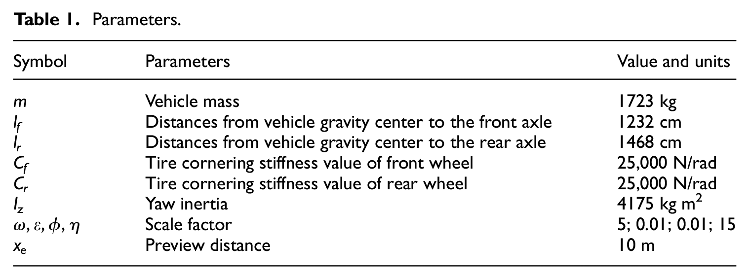
In this section, the simulations are carried out on Simulink–CarSim joint platform. The double-lane change (DLC) maneuver simulation case is presented to analyze the effect of RAIS’s delay on trajectory tracking performance and validate the effectiveness of the CS-AKP compensator. The parameters of vehicle model are listed in Table 1.
Parameters.
Analysis the influence of delay on trajectory tracking
To analyze the influence of the delay of RAIS, different delays are used in the simulation study. Assuming the maximum processing time of RAIS is 40 ms and the maximum transmission delay is 10 ms, and the maximum number of data packet dropout is 4, then by equation (24) we can identify the delay range is 0–80 ms. Five delays (τ = 0, 40, 60, 80, and 100 ms) are determined. And “τ = 0 ms” is used to simulate non-delay case, “τ = 100 ms” is used to simulate the case of system failure with large delay. In the simulation, the vehicle is made to complete a severe DLC maneuver at the speed of 40 km/h on the high-adherence road.
Figure 6 shows the Global trajectories of the IV at different delays. The result of non-delay case (τ = 0 ms) shows that the proposed trajectory tracking strategy can effectively control vehicle motion with high tracking accuracy. According to simulation results for other delays, it is identified that the global trajectories is much sensitive to the delay of RAIS. The delay will cause the response time of the controller to move backward. In addition, the longer the delay time is, the more violent the oscillation as well as the greater the oscillation of the vehicle trajectory will be, seriously affecting IV trajectory tracking accuracy and stability.

The Global trajectories of the IV at different delays.
Figure 7 shows the influence of different delays on heading errors

The simulation results for the heading errors
The peak value and RMS (root mean square) of the heading errors

The results for the peak value and RMS of the heading errors and lateral deviation: (a) Peak value and (b) RMS.
Analysis of trajectory tracking with CS-AKP compensator
According to the proposed delay compensation strategy, the CS-AKP compensator is added to the trajectory tracking control simulation. The simulation environment is the same as the previous section. The CS-AKP compensator is applied to compensate the different delays of RIAS (τ = 40, 60, 80, and 100 ms), and the compensated and uncompensated trajectory tracking results are compared and analyzed.
Figure 9 shows the comparative results of road trajectory and vehicle trajectory under different conditions. According to Figure 9(a)–(d) (τ = 40, 60, 80, and 100 ms), we can see that the performance of vehicle trajectory tracking is improved obviously when the CS compensator is used, and the compensated vehicle trajectory (CS-AKP Compensator) almost coincides with the zero-delay vehicle trajectory, and the oscillation in the trajectory is almost eliminated. It is identified that the proposed compensator has a good compensation effect for the delay of RAIS, and can maintain the vehicle trajectory tracking performance in a large delay range

The simulation results for vehicle trajectories with CS-AKP compensator at different delays: (a) τ = 40 ms, (b) τ = 60 ms, (c) τ = 80 ms, and (d) τ = 100 ms.
Figure 10 shows the simulation results for the heading errors and lateral deviation when the CS-AKP compensator is used at different delays. It can be seen that the delay of RAIS can substantially be attenuated, and the accuracy of heading error and lateral deviation are similar to that of non-delay case. Figure 11 shows the peak values and RMS values of heading errors and lateral deviations in different time delays (40, 60, 80, and 100 ms). With the CS-AKP compensator, the peak value of heading errors are 0.1303, 0.1297, 0.1292 and 0.1295, respectively; the RMS of heading errors are 0.3272, 0.03263, 0.03253, and 0.0324, respectively; the peak value of lateral deviations are 0.1579, 0.1576, 0.1566, and 0.155, respectively; and the RMS of lateral deviations are 0.052, 0.0528, 0.0534, 0.0538, respectively. The CS-AKP compensator is used to improve the heading error and lateral deviation performance of the system. The peak value and RMS of the heading errors and lateral deviations are very close to those of non-delay case. This proves the effectiveness of the compensator. In addition, the compensator can also work well even when the delay time is up to 100 ms.

The simulation compensated results for heading errors and lateral deviation at different delays: (a) Heading errors and (b) lateral deviation.

Peak value and RMS of heading error and lateral deviation with the CS-AKP compensator: (a) Peak value and (b) RMS.
To verify the superior performance of the CS-AKP compensator, the C-KF compensator is established using the Adaptive Kalman filter algorithm. Figure 12 is the simulation results of heading error and lateral deviation for C-KF compensator. Figure 13 shows the contrast results of peak value and RMS for the no-compensator, CS-AKP, and C-KF compensators. We can see that the CS-AKP and C-KF compensators can significantly improve the trajectory tracking accuracy and weaken the oscillation compared to the no-compensator. When the delay exceeds 60 ms, the performance of the CS-AKP compensator is significantly better. This is because the CS model is used in the CS-AKP compensator. The use of CS model can significantly improve the accuracy of target trajectory prediction and maintain high prediction accuracy even under large delays. The performance of the C-KF compensator is significantly degraded in the case of large delays. In addition, we can see that the CS-AKP and C-KF compensators can also eliminate the oscillation of the vehicle trajectory.

The simulation results of C-KF compensator: (a) Heading error and (b) lateral deviation.

Contrast results of no-compensator, CS-AKP, and C-KF compensator: (a) Heading error and (b) lateral deviation.
Conclusion
This article studies the impact of RAIS’s delay on the trajectory tracking accuracy of vision-guided IV, and thus a delay compensator based on CS model and AKP algorithm is proposed. Based on the joint simulation platform of Simulink–CarSim, a vision-guided IV trajectory tracking simulation model is established. The simulation results prove that (1) the delay of RAIS deteriorates the trajectory tracking performance of IVs, reduces the accuracy and stability of the trajectory tracking, and the longer the delay time is, the more obvious the impact will be, and (2) the proposed delay compensator, which combines the CS model and AKP algorithm, has a good compensation effect for different degrees of RAIS delay, and significantly improves the vehicle trajectory tracking performance. However, this article mainly focuses on the compensation of given delay. The delay of RAIS may be variably and unknown, which will be further verified in future studies.
Footnotes
Acknowledgements
We would like to thank Te Chen, Xiaohan Wu, Dehua Shi, Qing Ye of School of Automotive and Traffic Engineering of Jiangsu University.
Declaration of conflicting interests
The author(s) declared no potential conflicts of interest with respect to the research, authorship, and/or publication of this article.
Funding
The author(s) disclosed receipt of the following financial support for the research, authorship, and/or publication of this article: This work was funded by the National Natural Science Foundation, China (Grant no. U1564201, U1664258), the “Six Major Talent Project” of Jiangsu Province (Grant No. 2014-JXQC-004), the “333 Project” of Jiangsu Province (Grant No. BRA2016445), the Primary Research & Development Plan of Jiangsu Province (Grant No. BE 2017129), the Natural Science Foundation of Jiangsu Province (Grant No. BK 20160525) and the Natural Science Research Projects in Colleges and Universities of Anhui Province (Grant Nos. KJ2016B11 and KJ2017B11).