
Abstract
Due to the advantages of high stiffness, high precision, high load capacity and large workspace, hybrid robots are applicable to drilling and milling of complicated components with large sizes, for instance car panels. However, the difficulty in establishing an exact dynamic model and external disturbances affect the high accuracy control directly, which will decrease the machining accuracy and thereby affect the machining quality and efficiency of the system. Sliding mode control is an effective approach for high-order nonlinear dynamic systems since that it is very insensitive to disturbances and parameter variations. However, chattering may exist in traditional sliding mode control with fixed parameters, which results from a constant approaching speed. Besides, the approaching speed will affect the chattering strength directly. To solve these problems, a modified sliding mode controller with self-adaptive parameters is proposed to enhance the trajectory-tracking performance of a 5-degree-of-freedom hybrid robot. Firstly, the kinematic model of the robot is established. Then adopting the principle of virtual work, a rigid dynamic model of the robot is built. Based on the built dynamic model, a modified sliding mode control method is developed, of which the approaching speed is dependent on the system state. Finally, the sliding mode controller with self-adaptive parameters is created for a hybrid robot. The proposed sliding mode controller can achieve a rapid approaching speed and suppress chattering simultaneously. Simulation results demonstrate that the proposed modified sliding mode controller can achieve a comparatively accurate and smooth trajectory, which owns good robustness to external disturbances.
Introduction
Compared to serial kinematic machines (SKMs), parallel kinematic machines (PKMs) can achieve higher stiffness, higher load capacity and higher accuracy in theory. However, SKMs own higher flexibility. Therefore, hybrid robots, which are usually constructed by connecting a 2R manipulator to a PKM serially, have attracted much attention in recent years. For instance, the hybrid 5-degree-of-freedom (5-DOF) robots Tricept and Exechon have been applied in the drilling and milling of large-scale complex components successfully.1,2 Considering the structure features of the two hybrid robots, Huang et al.3,4 proposed a novel hybrid robot which is known as TriMule and the robot could be regarded as a plug-and-play functional module to construct different workstations. Some research related to performance evaluation, optimal design has been conducted in literature.5–7 Despite of the mechanical structure with good performance, the control of a robot is crucial to the high efficiency and high precision machining.
In general, the control methods of a robot fall into kinematic control methods and dynamic control methods. Usually, the kinematic control methods are simple in design and fast in calculation, which have been widely applied in industry. The PID control and PD control are commonly used kinematic control methods.8,9 Based on a simplified rigid dynamic model and in order to achieve good trajectory tracking performance for the high-speed parallel robot Delta, Wu et al. 10 established a nonlinear PD controller with nonlinear disturbance observer. Meanwhile, in order to enhance a controller's dynamic response and the anti-disturbance capacity, some intelligent algorithms have been added to the kinematic control methods. For example, Han et al. 11 presented a PID controller with fuzzy gain scheduling for a hybrid robot, which can suppress the control performance varying with robots’ configurations effectively. In order to isolate vibration, Taghizadeh et al. 12 presented self-tuning PID controller based on neural network for the Stewart platform, which also showed good robustness against external disturbances. Lee et al. 13 proposed a hybrid PID-sliding mode control method, which was proved to own good transient response and trajectory tracking performance simultaneously.
The dynamic control methods are mainly divided into dynamic feedforward control methods14,15 and computed torque control methods.16,17 Usually, the dynamic feedforward control mainly consists of a closed-loop kinematic control system and a dynamic control system. The closed-loop kinematic control system takes control of the servo system of kinematic links directly, which will suppress the effects of dynamic factors that cannot be compensated by the dynamic control system simultaneously. Due to the good stability, high speed and good accuracy, the PID controller is usually applied to design the closed-loop kinematic control system. The dynamic control system helps reduce effects of nonlinear dynamic characteristics on a controller, which will improve a system's dynamic response. Therefore, the dynamic feedforward control owns the merits of the kinematic control methods and can improve dynamic response of a controller simultaneously. Furthermore, some intelligent algorithms have been introduced to the closed-loop kinematic control system to reduce effects of dynamic parameters on the control performance.18–20 However, the dynamic feedforward control methods with intelligent algorithms are difficult to be realized in practice for the instability of intelligent algorithms, large calculation load and high requirement for a controller.
The computed torque control methods usually rely on a system's rigid dynamic model, based on which the required driving force/torque for a desired motion trajectory is obtained and is used to control each kinematic link subsequently. Therefore, the computed torque control can achieve comparatively high control accuracy. It can be known that the control performance is strongly dependent on the rigid dynamic model's modeling accuracy. In addition, results show that the control performance of a computed torque method will also be influenced by nonlinear factors during the motion process.21,22 Therefore, it is difficult for a simple computed torque method to obtain ideal control performance. Considering these issues, researchers improved the computed torque control method by introducing fuzzy control, adaptive control, and sliding mode control.23–25 For example, adopting a fuzzy adaptive reaching law, Zhao et al. 26 proposed a discrete sliding mode controller for a 6-PRRS parallel robot, which can achieve good performance with smooth control actions and minimum reaching time. By mixing and extending adaptive fuzzy sliding mode control and adaptive fuzzy sliding mode observer methods, Navvabi et al. 27 designed a controller for the 6-DOF Stewart manipulator, which was composed of a fuzzy controller and a robust switching controller in parallel.
It is noted that parallel/hybrid mechanisms are typical nonlinear time-varying and strong coupling systems with multiple inputs and outputs, of which dynamic characteristics, the gravity and the equivalent inertia for instance, are strongly configuration-dependent. For these complex systems, it is hard to build exact dynamic models due to the following two main reasons. One is that it is hard to obtain the real inertia parameters and dimensional parameters of a parallel/hybrid mechanism after parts are fabricated and assembled. The other is that some terms are usually neglected for the convenience of derivation, such as friction. Besides, as machining tools, there are some external disturbances, such as cutting force. The mentioned issues above will decrease the control behavior of a hybrid robot working as a machine tool, which will thereby influence the working accuracy and working efficiency of the system. Sliding mode control is an effective approach which can deal with control of high-order nonlinear dynamic systems under various uncertainty conditions. Furthermore, sliding mode control is very insensitive to disturbances and parameter variations, thus an exact model is not required.28,29
Based on the above discussions, a sliding mode controller will be developed for the TriMule robot. It is noted that if a large model uncertain happens, large switching control is required to ensure a stable reaching phase, which will result in chattering and thereby affect the system's machining accuracy. 30 In order to avoid the undesirable system chattering and achieve a rapid approaching speed, a modified sliding mode controller with self-adaptive parameters dependent on the system state is presented in the paper. The advantage of this controller is parameters dependent on the system state, which will lead to the approaching speed adaptive to the system state thereby. To be specific, the presented sliding mode control method can ensure that if the system state gets far away from sliding surfaces, the system will approach to sliding surfaces at an exponential rate. Contrarily, when the system state gets near sliding surfaces, the system state's speed approaching to sliding surfaces will become smaller and smaller until 0, which thus can suppress system chattering efficiently. Compared to traditional PID control, the proposed sliding mode control can achieve higher control behaviors for the system's dynamics is considered and it is not sensitive to disturbances. Compare to traditional sliding mode control with fixed parameters, chattering will be suppressed, thus can achieve a much smooth trajectory.
The remainder of this paper is constructed as follows. In Section 2, mechanical structure and kinematic model of the TriMule robot are introduced. Based on the principle of virtual work, the rigid dynamic model is built in Section 3, which will be used in the subsequent controller design. A modified sliding mode controller is presented in Section 4, of which the stability is proved by the Lyapunov functions. Based on a typical reference trajectory, the control performance of the presented sliding mode control is evaluated in Section 5. Finally, some conclusions are summarized.
Kinematic modeling of the hybrid robot
Structure of the TriMule robot
As can be seen from Figure 1, the hybrid robot is mainly constructed by a parallel kinematic machine module and a serial 2R kinematic machine module. There are four kinematic links in the parallel kinematic machine module, three of which are active while one is passive. Three active links are connected to the base through universal joints, while connected to the platform by spherical joints. The passive link is connected to the base by a universal joint while attached to the platform fixedly. The serial 2R kinematic machine module mainly consists of two perpendicular axes, i.e. A-axis and C-axis. Thus, the hybrid robot can achieve 5-DOF when driven by 5 servomotors independently, which can be used for drilling and milling of large-scale complex components, such as aircraft panels in the aerospace industry.
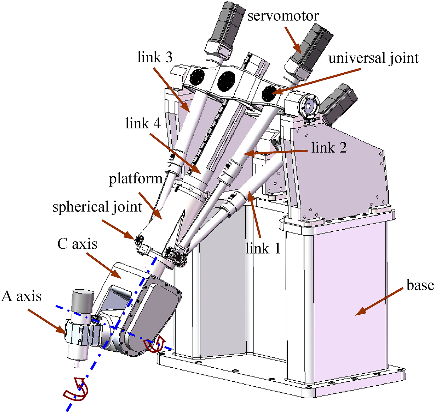
3D model of the 5-DOF TriMule robot.
The schematic diagram of the robot is shown in Figure 2. For the convenience of derivation, the following coordinate frames are established. As shown, the geometrical center of the spherical joint in link j is denoted as Aj, while that of the universal joint in link j is denoted as Bj (j = 1∼4). To be specific, A4 is the attached point on the interface of link 4 and the platform. Cj denotes the end point of the jth link. The A axis and C axis intersect at point P. And the end point of the machine tool is expressed as C. The system's global coordinate frame B4-xyz is built at the geometrical center of the universal joint B4, with the x direction pointing from points B4 to B2 and the y direction vertically up to segment B3B2. Then the z direction could be decided definitely by the right-hand rule. The platform's coordinate frame A-xAyAzA is built at the center of segment A3A2, of which the xA direction is along the segment A3A2 and the zA direction is vertical to the platform. Similarly, the yA direction is determined through the right-hand rule. The body-fixed coordinate frame of the A axis is set at point C, where the xc direction is along the rotation axis of the A axis while the zc direction is along the machine tool's axis. Accordingly, the yc axis can be determined through the right-hand rule. The coordinate frame of the ith link Bi-xiyizi is established at point Bi, with the zi direction along the ith link and the yi direction along one of the rotation axes of the ith universal joint (i = 1∼3). Accordingly, the xi direction is decided through the right-hand rule.

Schematic diagram of the TriMule robot.
The hybrid robot's kinematic model has been included in our previous work, 4 which will not be described hereby. Velocity and acceleration analysis will be built in this section, and will be applied in the subsequent dynamic modeling of the hybrid robot.
Velocity analysis
In the system's global coordinate frame B4-xyz, position of point A can be described as


Taking derivation of (1) and (2) leads to


In order to eliminate


Substituting (6) into (5), one can obtain


One also can take inner dot of (4) by
To obtain the ith active link's angular velocity, one can take cross product of (3) by


Acceleration analysis
Taking derivation of (8) yields


Taking derivation of (6), the platform's angular acceleration can be obtained as

Taking derivation of (11), the ith active link's angular acceleration can be expressed as


Dynamic modeling of the hybrid robot
In this section, the rigid dynamic model of the hybrid robot will be built according to the principle of virtual work. For the convenience of derivation, the following are assumed.
All the joints are assumed to be ideal. Inertia of the universal joints connected to the base is neglected. All the limbs are axisymmetric rigid bodies, of which inertia matrices in their body-fixed coordinate systems are diagonal. The 2R serial mechanism module is regarded as a lumped mass model attached to the platform. However, inertia of the lumped mass model is configuration-dependent.
System component decomposition and kinematic description
The structure diagram of passive and active links is depicted in Figure 3. According to the above assumptions and motion characteristics of the four links, one can divide the passive and active links into different motion parts, respectively. The passive link can be regarded as a component in general rigid body motion, of which the mass center is D4. As shown, the passive link is divided into three components named Si,
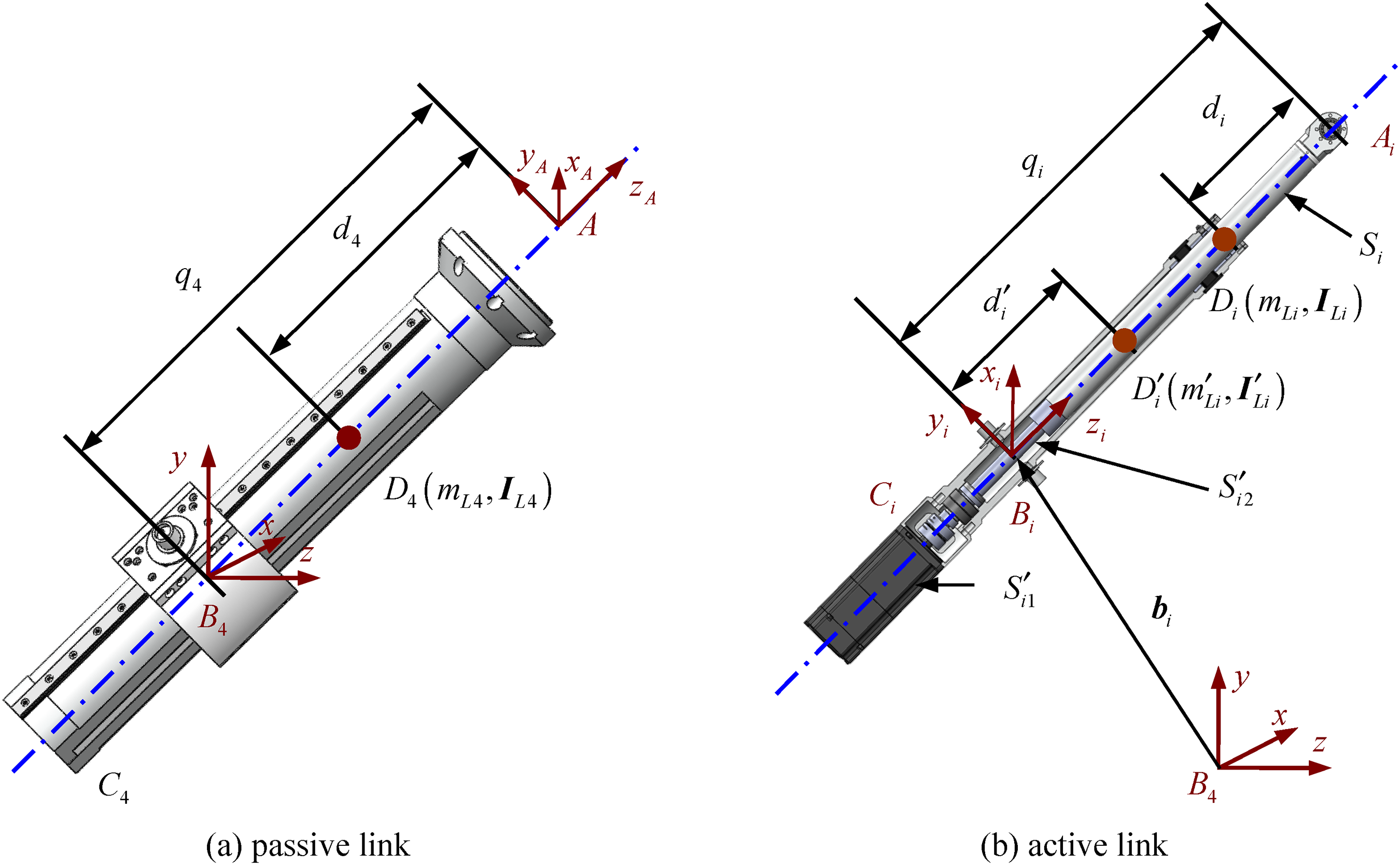
Structure diagram of passive and active links in TriMule.
In the global coordinate frame B4-xyz, position vector of the mass center D4 can be denoted as

Taking derivation of (16), one can obtain the velocity of the mass center D4 as

Accordingly, in the global coordinate frame B4-xyz, position vector of the mass center Di can be expressed as

Taking derivation of (18), one can obtain the velocity of the mass center Di as

Taking derivation of (17) and (19), one can obtain the acceleration of the mass center Dj as

Based on the velocity superposition principle, the absolute angular velocity of component

Taking derivation of (21), one can obtain the angular acceleration of component

Virtual work of the active link
The gravity and inertial force applying at the mass center Di of component Si is denoted as

The inertial moment of component Si can be expressed as

The moment of the gravity about point Bi of component

The inertial moment of component

The inertial moment of component

The virtual work conducted by the inertial moment of component

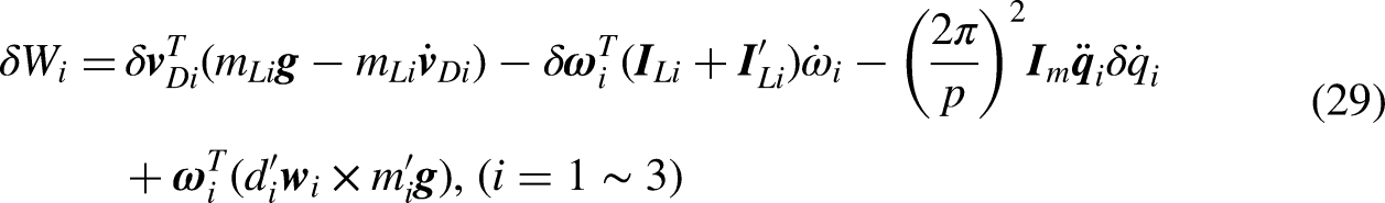
Thus, the virtual work conducted by the active limb can be derived as
Virtual work of the passive link
The gravity and inertial force applying at the passive link's mass center D4 can be expressed as

The inertial moment of the passive link can be expressed as

Thus, the virtual work conducted by the passive link can be expressed as

Virtual work of the platform
The gravity and inertial force applying at the platform's mass center A can be denoted as

The platform's inertial moment can be obtained as

Therefore, the platform's virtual work can be expressed as

Rigid dynamic model of the system
Supposing that the driven force is


Therefore, the driven torque can be obtained as

Sliding mode control model
Traditional sliding mode controller
Considering uncertain factors, the driven torque can be expressed in the joint space as

In order to facilitate the design of controller, the following assumption is made

Sliding mode control owns the advantages of fast response, strong robustness, and good adaptability especially for non-linear systems. A sliding surfaces vector is defined hereby as

Based on (42), the following exponential reaching law is adopted

Taking derivation of (42), one can obtain

Combining (44) and (45), the following can be derived
There exists

Substituting (42) and (46) into (40) and neglecting the uncertain term, one can derive the control law of the system expressed as
Modified sliding mode controller
As can be seen from (44), when the system state gets far away from sliding surfaces, i.e. the sliding surfaces vector

Based on (49), one can derive
Conversely, when the system state gets near sliding surfaces, i.e. the sliding surfaces vector

Therefore, in order to achieve a rapid approaching speed and suppress chattering simultaneously,

As can be seen from (52), when the system state is far away from sliding surfaces, i.e.
A control framework is illustrated in Figure 4. Herein, x, y, z, α and β are configurations of the tool center point and tool orientation;

Block diagram of the modified sliding mode controller.
Stability analysis
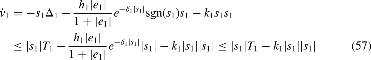
In order to analyze the proposed modified sliding mode controller's stability, a Lyapunov function vector is defined


Case study
The main geometrical parameters and mass parameters of the hybrid robot are listed respectively in Tables 1 and 2. It should be worth noting that inertia parameters listed in Table 2 are measured in each part's body-fixed coordinate system.
The hybrid robot's geometrical parameters (unit: mm).

The hybrid robot's mass parameters (units: kg, kg·m2).

Description of a specified path
In order to facilitate analysis, a typical “S” path is shown in Figure 5. Ps and Pe denote the starting point and ending point of the path. P2, P3 and P4 are tangent points of every two adjacent arcs. P3-x′z′ denotes the path body-fixed coordinate frame, with the x′ direction parallel to the x direction. R1 and R2 denote radii of arcs PsP2 and P4Pe, and arcs P2P3 and P3P4 respectively. A machining angle is defined as γ, which describes the rotation angle of the local coordinate frame P3-x′z′ about the x′ axis with respect to the global coordinate frame B4-xyz. It is noted that the tool axis should be kept perpendicular to the path plane.

A typical path defined in a local coordinate frame.
As a result, position of a point in the specified “S” path can be described in B4-xyz as
As could be known from the above analysis, position of the typical “S” path can be entirely decided by the machining angle γ and the position of point P3. In order to keep the typical “S” path in the robot's workspace, point P3 is fixed in the center of the robot's task workspace.
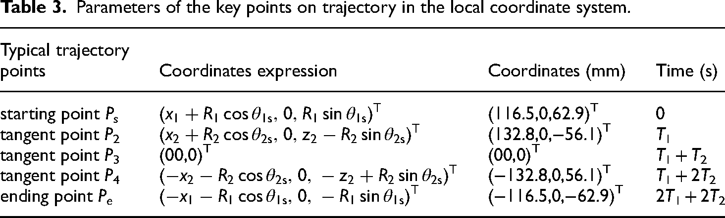
To facilitate the following analysis, the motion time of arcs PsP2 and P4Pe are set to be the same, which is denoted as T1. Similarly, the motion time of arcs P2P3 and P3P4 are set to be the same and denoted as T2. Therefore, the required total motion time is 2(T1 + T2). Coordinates of key points on the typical path are shown in Table 3. Herein, x1 denotes the coordinate of point Ps in the x′ direction; x2 and z2 are coordinates of point P2 in x′ and z′ directions respectively; θ1s and θ2s denote angles between o1Ps, o2P2 and the x′ direction, respectively.
Parameters of the key points on trajectory in the local coordinate system.
For the above typical path, set T1 = 4.23 s, T2 = 3.77 s and γ=−9.18°. Meanwhile, the 7-order B-spline is adopted to conduct trajectory planning. This is the optimal result when adopting the 7-order B-spline by considering vibration errors and energy consumption simultaneously, which will not be analyzed in this paper.
Verification of the dynamic model
In order to verify the established dynamic model, one can build a simulation model in MATLAB/Simscape. Taking the typical “S” path addressed above as an example, trajectory planning can be conducted by adopting the 7-order B-spline, from which the command position, command velocity and command acceleration of servomotors can be obtained. Taking the command position, velocity and acceleration of servomotors into the simulation model, one can obtain the driving torque of three servomotors in the parallel mechanism module.
Comparison of driving torque between the theoretical model and Simscape model is shown in Figure 6. As can be seen, the driving torque curves of each servomotor based on the theoretical model and the Simscape model do not coincide completely since that limbs and the moving platform are axisymmetric in the theoretical model. However, the driving torque of the theoretical model is in conformity with that of the simulation model, between which the difference is relatively small. Therefore, the established dynamic model own good accuracy and can be used to the dynamic control of the hybrid robot.
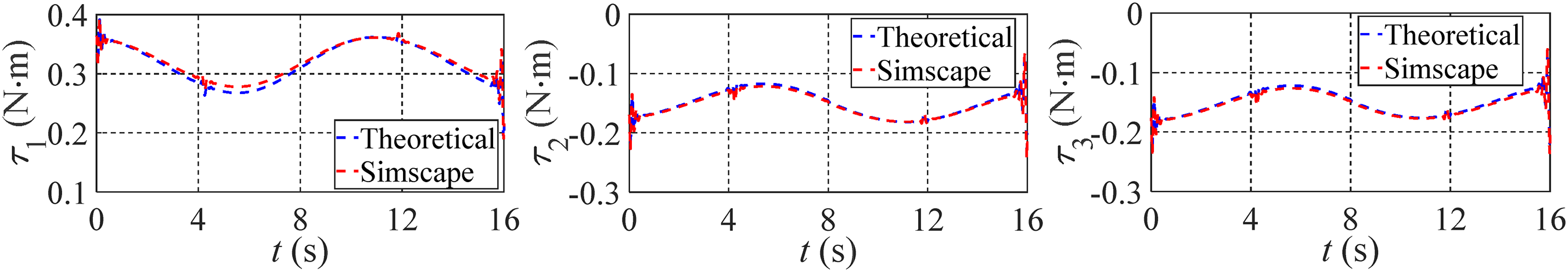
Comparison of driving torque between the theoretical model and Simscape.
Control behavior analysis
Based on the above parameters, the control algorithm is implemented by combining MATLAB/Simulink and MATLAB/Simscape. Meanwhile, to simulate as realistically as possible, some disturbance is added to the simulation model. The imposed external disturbance torque in the simulation model is white noise, which obeys normal distribution N (0,0.02) as shown in Figure 7.
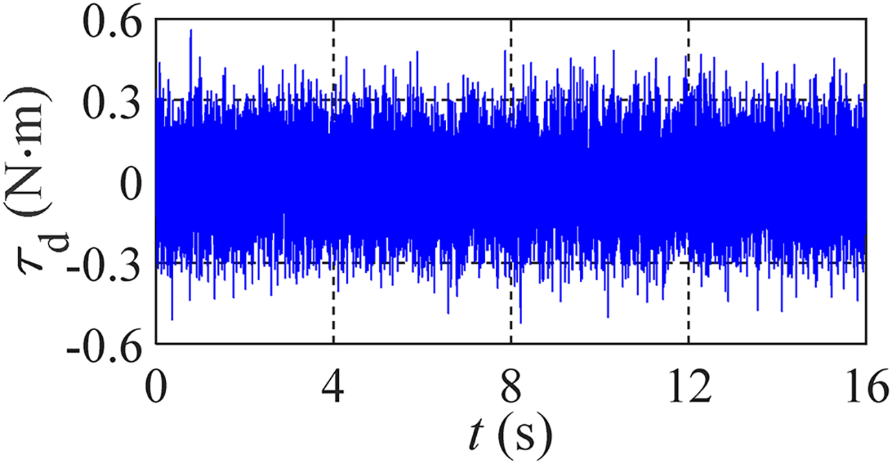
Imposed external disturbance torque.
For comparative analysis, the control behaviors of the PID control, the sliding mode control with fixed parameters (SMC) addressed in Section 4.1 and the proposed modified sliding mode control (MSMC) are shown in Figure 8, simultaneously. Herein, e1, e2 and e3 denote the tracking errors of three servomotors, respectively.

Tracking-trajectory results of three active links under the reference trajectory.
As can be seen, the three active servomotors own good tracking performance no matter the PID control, the proposed MSMC or the SMC with fixed parameters is adopted. In general, the control performance of the proposed MSMC and the SMC with fixed parameters is much better than that of PID control. It is due to that the PID control do not consider the change in system's inertia and dynamics. Furthermore, compared to the SMC with fixed parameters, tracking errors of three active links are much smaller and much smoother when adopting the proposed MSMC. That is to say, the proposed MSMC can decrease tracking errors of active joints efficiently due to the self-adaptive parameters dependent on the system state. As can be seen, the three active joints’ maximum tracking errors don’t exceed 0.02 rad when adopting the proposed MSMC. Accordingly, the root-mean-square error is remarkably reduced from 0.039 rad to 0.011 rad when the proposed MSMC is applied to track the reference path.
Tracking errors of the proposed MSMC under three different working conditions are shown in Figure 9. Herein, dis 0 denotes the case where no disturbance is considered, dis 1 is the case where only external disturbance torque is considered while dis 3 is the one where external disturbance torque and the system's damping are considered simultaneously.
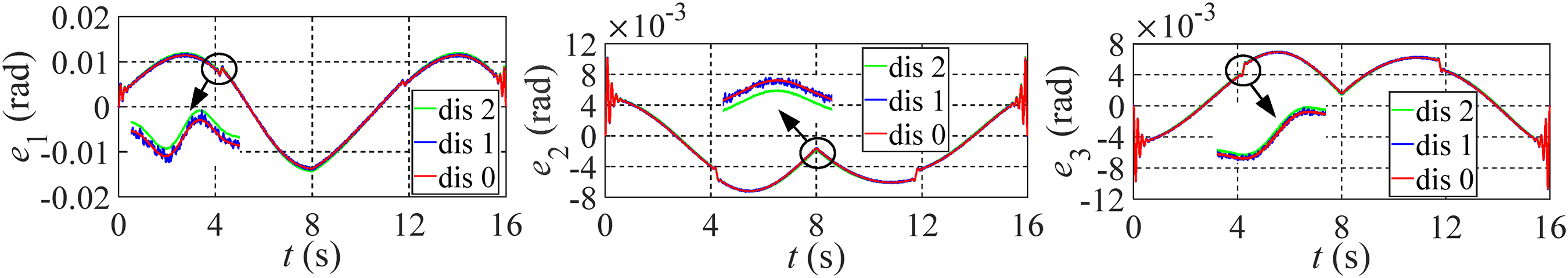
Tracking errors of the proposed MSMC under different disturbances.
As can be seen from Figure 9, variations of position errors under three working conditions are consistent. Besides, the difference in each servomotor's position error among three working conditions is relatively small. This demonstrates that the proposed MSMC owns good robustness, which can assure the stability of the control system.
Conclusions
A method on motion control of a 5-DOF hybrid robot is proposed in this paper. Main conclusions are drawn as follows.
In order to achieve a rapid approaching speed and suppress chattering simultaneously, a modified sliding mode control method with self-adaptive parameters dependent on the system state is proposed. The proposed MSMC could assure that the system will approach to sliding surfaces at an exponential rate when the system state gets far away from sliding surfaces and the speed of the system state approaching to sliding surfaces will become smaller and smaller until 0 when the system state gets near sliding surfaces. Time derivation of the Lyapunov function confirms that the proposed MSMC owns good robustness to model uncertainty, which can assure the stability of the control system. Compared to the traditional PID control and SMC with fixed parameters, the proposed MSMC can decrease tracking errors of the system efficiently. Furthermore, control performance of the proposed MSMC is much smooth. The proposed MSMC is proved to be an effective and practical control method for the hybrid robot, which is possible to be applied to other robots with some modifications.
Footnotes
Declaration of conflicting interests
The authors declared no potential conflicts of interest with respect to the research, authorship, and/or publication of this article.
Funding
The authors disclosed receipt of the following financial support for the research, authorship, and/or publication of this article: This work was supported by National Natural Science Foundation of China (52405036), the China Postdoctoral Science Foundation (2023M732984), EPSRC projects (EP/P026087/1, EP/P025447/1) and the European Union's Horizon 2020 research and innovation programme (No. 734272).