
Abstract
In order to accurately improve and predict chatter stability region of machining process, an optimization method of machining process with non-uniform allowance of integral impeller was proposed. The modal parameters of the workpiece process system were obtained using the finite element analysis. Based on the regenerative chatter analysis theory, a limit comparison diagram of the stability with uniform allowance and non-uniform allowance was established. The simulation results showed that the non-uniform allowance natural frequency is about 1.43 times as much as the uniform allowance natural frequency, and the machining system stiffness non-uniform allowance is twice as much as the uniform allowance, while the limit of chatter stability region is increased by 3 times. This article studied uniform allowance and non-uniform allowance of milling chatter stability with experimental method. Tool path for five-axis machining and machine tool simulation based on NX CAM were planned. The comparisons of cutting processing uniform allowance and non-uniform allowance were done, and the surface profile detection of the test part with the three-dimensional scanning was carried out. The experimental results showed that the average optimization rate for manufacturing precision of blade suction surface after optimization and pressure surface was 63.8% and 48.84%. The total experiment showed that this process optimization strategy could effectively improve the stiffness of the integral impeller blade and reduce the cutting chatter of the blade during the cutting process.
Keywords
Introduction
Integral impeller with complex surface is the core component of the power propellers; a good surface precision is of great importance. In order to meet the aircraft’s requirements of high reliability, lightweight structure, and stealth capabilities, the integral impeller components of complex curved surface need to maintain high rigidity, high stability, and long-life performance under severe working conditions such as high temperature and high pressure.
In order to solve these problems, many experts and scholars have also conducted extensive researches. Srivastava et al. 1 simplified the blades to cantilever beams and designed in two shapes. One is a regular shape and the other is a regular trapezoidal blade. At the same time, the external force of the same load was applied. It was found that the deformation of the cantilever beam with trapezoidal shape was significantly lower than that of the conventional shape. Huang et al. 2 modeled the cutting force of the tool–workpiece joint at the end of the face milling, and the direction of synthetic cutting force was adjusted in a plane with relatively high blade stiffness, then a tool orientation determination method for vibration and deformation reduction in cutter milling was proposed. Li et al. 3 proposed a novel strategy and methodology to predict the chatter stability for milling process with large axial depth of cut. Through receptance coupling substructure analysis (RCSA) and zeroth-order approximation (ZOA), they obtained the actual tool-point position corresponding to different axial depth of cut and the effect of tool-point position on the predicted stability lobe diagram (SLD). Zhang and Liu 4 completed the motion equations of ball-end milling cutter; the cutting force model considering regenerative effect was built by evaluating the dynamic thickness at each cutting point along the cutting edge. They used the full discretization method and obtained the SLD of ball-end milling. Dai et al. 5 used a simple and effective semi-analytical method to extract the engagement amount (BWE) of the five-axis milling ball–workpiece. The residual amount of the workpiece surface after machining is considered and then established the SLD by Floquet theory. In order to identify the microend mill dynamics, Singh and Singh 6 obtained the frequency response function for the microend mill by finite element method modal analysis and has been verified from the experiment. It can be used for chatter prediction in high-speed micromilling operations. Ding and Zhu 7 considered the effect of material removal on the dynamic characteristics of thin-walled parts and each milling process of thin-walled parts. Based on the frequency domain method, three-dimensional (3D) milling flutter stability domains at different processing stages are established. The validity of the stability region was verified by experiments. Pelayo et al. 8 proposed a time-domain method to predict the stability of milling tools. Dynamic cutting forces were first obtained and then used it to draw SLD. At the same time, the influence of cutter orientation angle and cutter modal on the stability leaf map was considered. Finally, milling experiments were performed on the mechanical system with weak stiffness to verify the correctness of the model.
This article proposes a non-uniform allowance (NUA) processing method of thin-walled parts with complex surfaces. The machining process of impeller is optimized, and the tool path planning is carried out. The authors select a certain type of impeller blade machining experiments in actual manufacture to analyze.
NUA optimization strategy
The blade is layered in direction

When

When

The thickened value

The process design with NUA shown in Figure 1 was performed.
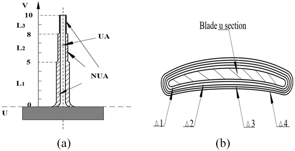
Non-uniform allowance process design diagram: (a) blade non-uniform allowance design and (b) blade u section reservation.
Figure 1(a) shows the design of a NUA process for a single blade, and Figure 1(b) shows the blade u section reservation. The blade’s surface equation can be defined as S(u, v); the direction of the cross section of the blade is u; the direction of the blade height is v; the blade is layered in the v direction.
The blade is equally divided into 10 parts in direction v. The part of 0–5 is represented by L3, and the part of 5–8 is L2, then the left part of 8–10 is L1. In the direction of cross-sectional area v, the segments of L1, L2, and L3 are thickened by 0.2, 0.35, and 0.6 mm.
When the reserved margin of the blade
Chatter stability region for integral impeller
Chatter analysis method
The dynamic model of thin-walled milling process is the theoretical basis of chatter stability. Based on the two-dimensional stability theory, 9 the 3D chatter stability model of the whole impeller was studied in the semi-precision/finishing stage. The machining process of the blade can be simplified into the machining process system which is shown in Figure 2.
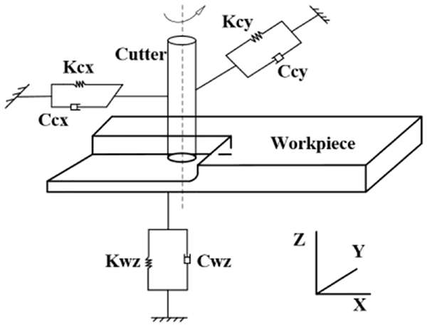
Dynamic milling model of thin-walled parts.
According to Altintas, 10 3D modeling of ball-end milling cutter in milling process was established to obtain the dynamic cutting force of the system

where
The effective milling direction coefficient

where
By substituting formula (3) into formula (2), the dynamic milling force can be expressed by

t is the present time and T is the tool period, the relative dynamic displacements between the work and tool at the present


When chatter occurs, the frequency can be defined as


The regenerative displacement function can be expressed by

By substituting formula (5) into formula (4), the final dynamic milling force formula can be expressed by

Cutting chatter 3D stability model can be obtained. The chatter stability of the whole impeller milling depends on the characteristic equation of the dynamic cutting force of the 3D milling system, 11 which is

The eigenvalues are

The critical cutting depth of the whole impeller based on the 3D chatter stability analysis theory can be obtained by substituting

Finite element analysis of blade milling chatter
The single blade is 45 mm in height and 60 mm in length; blade materials were titanium alloys. The thickness at the (thickest) blade root is 1.9 mm, and the thickness at the crown (thinnest) blade is 0.9 mm. According to the design of NUA in Figure 1, NUA model and UA model were imported into the Workbench to analyze the stiffness. Pressure was applied on the upper surface of the two types of blades with a size of 200N. The deformation of the two types of blades under the action of force is shown in Figure 3.
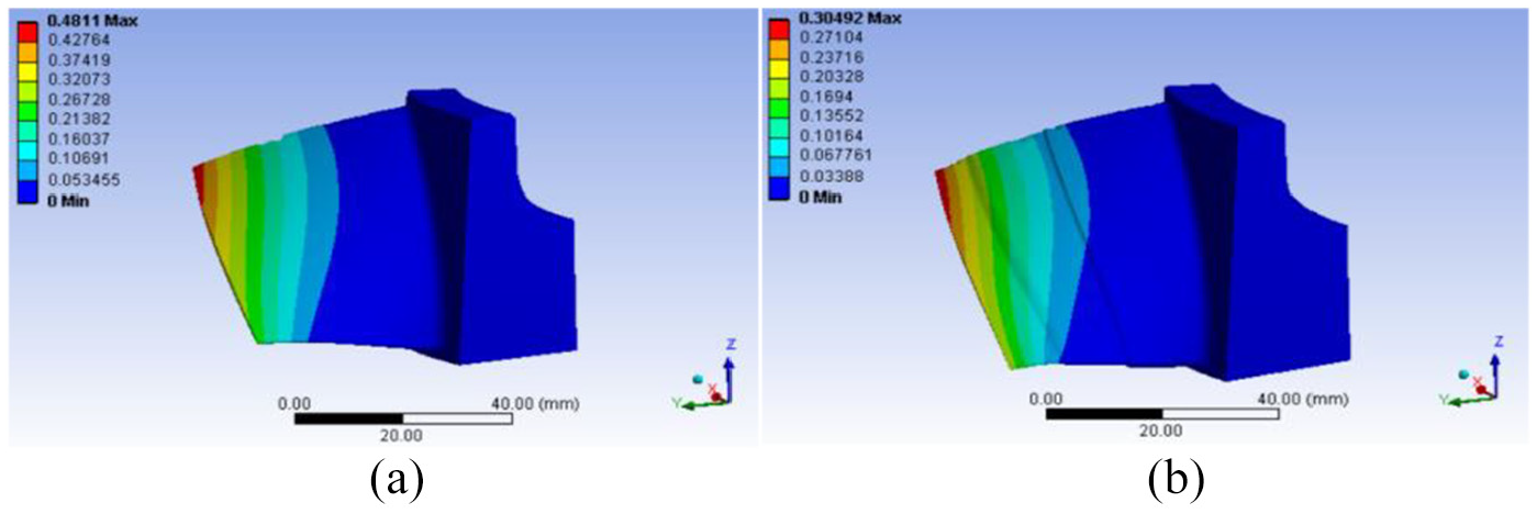
Stress nephogram of the UA and NUA: blade deformation with (a) UA and (b) NUA.
As shown in Figure 3, under the same 200N force, the maximum deformation of UA is about 0.481 mm, and the maximum deformation of NUA is about 0.305 mm.
After the two static analyses, the modal parameters of the two types of blades are analyzed. The analysis results are shown in Figure 4. The natural frequencies and damping ratios of the two types of blades are obtained. When two types of blades are milling on the same five-axis machine and tool, the stiffness of the machine tool system is approximate. In the simulation analysis, the modal quality of the workpiece is set as 1 to facilitate the analysis process.
12
Considering that the first-order natural frequency has a great influence on the blade, the stiffness of the workpiece system can be calculated according to the formula


where
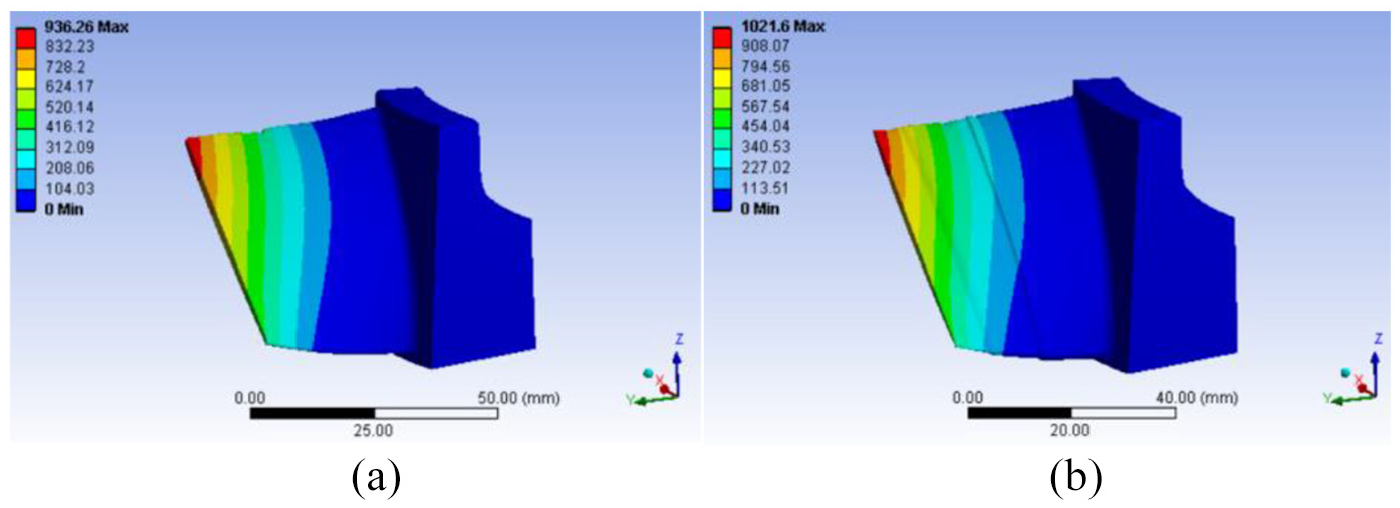
First order modes frequency of UA and NUA: first order mode of (a) UA and (b) NUA.
Modal parameters of UA and NUA.
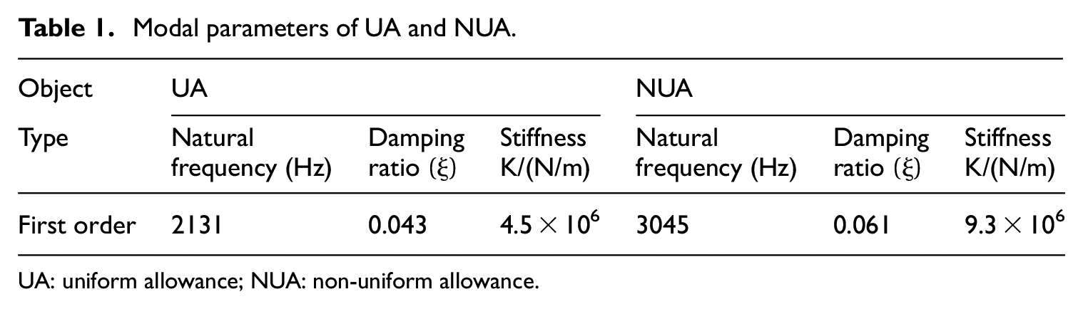
UA: uniform allowance; NUA: non-uniform allowance.
The results show that the natural frequency of the NUA blade can be improved obviously after the process optimization. The natural frequency after optimization is about 1.43 times of that before optimization. The stiffness of the UA blade is significantly lower than that of the NUA blade, which can significantly improve the stiffness of the machining system. The deformation of the UA blade is about 1.58 times as much as NUA, which proves that the process optimization strategy can significantly reduce the deformation of the blade.
Simulation of chatter stability region
Considering that the blades are weakly rigid, the transfer function of the process system is equal to the sum of the machine tool system and the machine tool–workpiece. 13 The relative transfer function of the whole machining system is

where
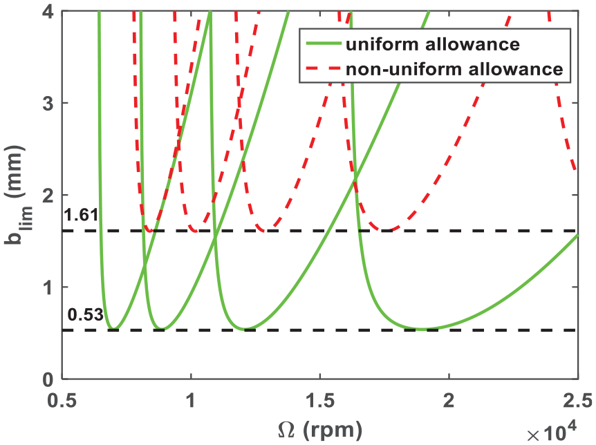
Chatter stability regions of UA and NUA.
The table of the chatter stability region of the two blades can be obtained from the chatter stability region, as shown in Table 2.
Comparison of stability limits of blade chatter.

UA: uniform allowance; NUA: non-uniform allowance.
From Figure 6 and Table 2, the chatter stability limit of the NUA blade can be improved, which is about three times of the limit cutting depth of the UA blade. Milling chatter can be suppressed, and machining efficiency can be improved. The NUA blade changes the shape of the blade before finishing and increases the natural frequency of the blade, so that the stable lobes move right. As the modal stiffness of the workpiece increases, the vibration between the workpiece and the cutter decreases, the limit axial cutting depth increases, and the chatter stability region of the milling machine increases as well.
Tool path and tool path visualization 3D dynamic for roughing.
Milling machining experiment of UA and NUA
Experimental conditions
Milling conditions are shown in Table 3.
Milling conditions.

UA: uniform allowance; NUA: non-uniform allowance.
Most of the impellers in the automotive and aerospace industry are made of aluminum, which has good cutting, mechanical properties, and extensive application. Therefore, this experiment uses 2A50 aluminum with high-strength wrought. According to the selected raw material, the selected tools are carbide tool because of the limitations of the experimental conditions. 14
The axial flow type integral impeller with complex surface curve is taken as the object in this experiment with the maximum diameter of
According to the selected impeller model, the tool path planning of the impeller is performed in the NX software.
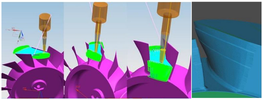
In the process of roughing, the back and forth rising mode can reduce the noncutting stroke and improve the cutting efficiency. Cutting tools of suitable size and shape are created, cutting direction is select. The impeller channel is divided into three layers of roughing and the allowance is increased in layers. The cutting force can be effectively reduced by reducing the cutting speed of the first tool because the first tool performs full cutting in each layer of cutting. 15 The tool path planning and simulation results of roughing for impeller are shown in Figure 6.
In the process of roughing, the surface of the blade is machined by surrounding the blade, and down milling is established along the guide edge. By choosing proper tilt clearance angle, lead/lag at leading edge, and lead/lag at trailing edge, it can ensure that the tool avoids interference effectively when cutting at high speed in a narrow channel. The cutting layer is provided with a certain overlapping area to avoid cutting marks. In order to reduce the change of the swing angle of the tool axis, the smoothness percentage of the tool rail and the tool axis is increased. 16 The tool path planning and simulation results of finishing for impeller are shown in Figure 7.
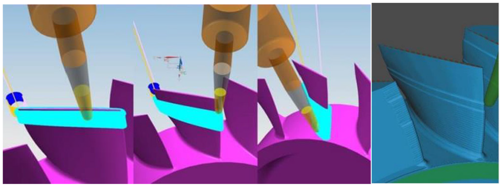
Tool path and tool path visualization 3D dynamic for finishing.
This comparative experiment is performed on an integral impeller to complete the balance between the uniform blade and the non-uniform blade. Figure 8 shows the integral impeller processing pictures at the scene.
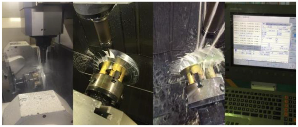
Producing spot.
Experimental results
According to the set process design comparison test of NUA optimization, the comparison between the two groups of impeller blade machining experiments is shown in Figure 9. The error of the impeller blades is produced due to the machining distortion and tool path planning errors. Figure 9(a) and (b) is the comparison results of the two types of blades after roughing; Figure 9(c) and (d) is the comparison results of the two types of blades after finishing. Under the traditional blade processing scheme with UA, the chatter at the blade crown in Figure 9(c) is produced and the surface quality is poor. When NUA is used for blade finishing, there is no chatter on the blade surface as shown in Figure 9(d), and the surface quality is good. It is verified that the NUA process optimization strategy can significantly inhibit the milling chatter, and that the reason for the optimization strategy is to change the modal parameters of the machining system. The stability region of the machining system is greatly improved to avoid the occurrence of chatter.
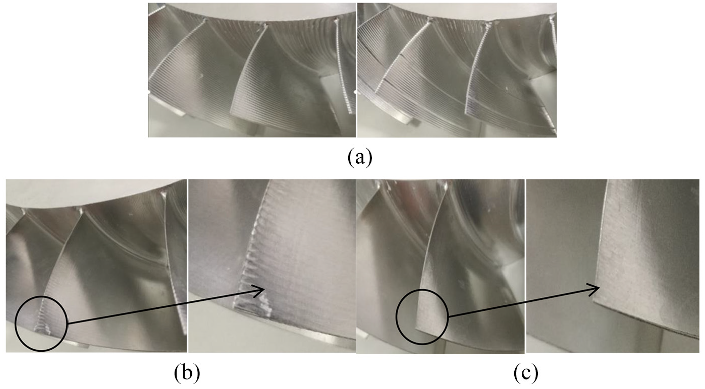
Impeller surface contour precision of UA and NUA: (a) roughing blade of UA, (b) roughing blade of NUA, (c) finishing blade of UA, and (d) finishing blade of NUA.
Blade surface contour precision test
Surface treatment and mark point will be set on the blade, and then the scanner is fixed and calibrated. After the 3D point cloud is stitched according to the marker points, the ASC and STL files are outputs from the point cloud data. The scanned data are read and reconstructed by Geomagic reverse engineering software. In this way, we can obtain the test results.
The processed blade is compared with the model used for tool path planning in NX. According to the data detected in Figure 10, six sets of data of the suction surface and the pressure surface after optimization are randomly selected to obtain the surface profile detection data table, as shown in Table 4.

Suction and pressure surface test results: (a) UA suction and pressure surface detection and (b) NUA suction and pressure surface detection.
Average deviations of the suction and pressure surfaces of the UA and NUA.

UA: uniform allowance; NUA: non-uniform allowance.
According to the data obtained in Figure 10, the optimized polyline diagram of the suction surface and the pressure surface is shown in Figure 11.

Contrast figure of blade surface contour UA and NUA.
The design error of the impeller’s technical file in this example is the surface profile from −0.05 to +0.25. In Figure 11, the results show that the optimized blade has an average optimization rate of 63.8% for the manufacturing precision of the suction surface and the average optimization rate of 48.84% for the manufacturing precision of the pressure surface.
From this experiment and test, it is also demonstrates that the method of finishing NUA is adopted with the impregnability of the geometric conditions of the blade and the design parameters. On the one hand, the finishing allowance at the low stiffness of the blade is appropriately reduced, and the finishing allowance at the better stiffness is increased by reducing the machining distortion caused by the cutting force in the blade machining process. On the other hand, the NUA processing method has a larger allowance at the root and the middle part, while a smaller allowance at the tip and the edge. The thickness of the supporting part during the processing of the blade is strengthened, and the rigidity is enhanced. Therefore, we can improve the stability of the cutting process from two aspects, which are optimization of machining cutting force and optimization of workpiece rigidity.
Conclusion
The study takes aerospace aluminum alloy 2A50 thin part as the research object and studies the effect of process optimization on impeller milling chatter. The conclusions are as follows:
For the impeller with complex surface, the NUA optimization strategy was proposed to strengthen the rigidity of the parts with weak rigidity structure. For different types of blades, different thickening methods are proposed based on machining experience.
The deformation analysis and the vibration modal analysis of the two types of blade structure were performed. The natural frequency after optimization is about 1.43 times of that before optimization. The stiffness of the UA blade is significantly lower than that of the NUA blade, which can significantly improve the stiffness of the machining system. The chatter stability limit of the NUA blade can be improved obviously, which is about three times of the limit cutting depth of the UA blade.
The results of machining experiments show that the surface quality and accuracy of the NUA blade is higher than the UA blade, and the surface is smooth without chatter. Using a 3D scanner to measure the profile of the impeller blade, the test results show that the optimum optimization rate of the manufacturing precision of the suction surface was 63.8%, and the average optimization rate of the manufacturing precision of the pressure surface was 48.84%.
Experimental result reveals that NUA process can effectively improve process rigidity of workpiece and guarantee the stability of cutting process compared to traditional UA process. At present, the process optimization strategy had been applied to actual manufacturing.
Footnotes
Declaration of conflicting interests
The author(s) declared no potential conflicts of interest with respect to the research, authorship, and/or publication of this article.
Funding
The author(s) disclosed receipt of the following financial support for the research, authorship, and/or publication of this article: The research is financially supported by the National Natural Science Foundation of China under grant number 51405304 and Key Support Plan of Shanghai Science and Technology Committee (170905038000).