
Abstract
Blend features usually exist in the machining of complex multi-cavity parts; however, the ideal linear boundary of the cavity is shown as an arc curve at actual corner machining, which affects the accuracy of a robot’s tool feed position. Focused on this problem, this article presents an automatic tool path planning approach based on blend feature simplification. By analyzing the geometric elements of blend feature, a line segment is constructed to obtain the machining boundary, while the robot tool feed position is accurately measured. On this basis, the coordinates of a robot tool feed position are assigned to the machining element, which can be used to calculate the spatial distance between different cavities. Then, an improved genetic algorithm is applied to improve the optimization of the tool path. The automatic decision of the corresponding work steps is realized by merging and sorting the machining elements. Finally, a corresponding prototype system is presented, with the correctness and validity of the proposed approach being examined, using aircraft structural part machining as an illustrative example.
Keywords
Introduction
A cavity is a common structure in an aircraft structural and mold design. It is usually processed by a robot or computer numerical control (CNC) milling.1–3 Aircraft structural parts are usually large in size and multi-cavity (the overall size can reach 4000 mm × 2000 mm); in this instance, cavities tend to be far apart from each other. In addition, the robot tool path planning of multi-cavity parts must consider each cavity’s profile and its spatial position relationship, keeping the machining mode unchanged and minimizing the number of tool changes required.4,5
The robot tool path optimization is often summarized as the traveling salesman problem (TSP).6,7 These recognized problems often use heuristic algorithms to obtain approximate solutions, the most common of which are genetic algorithms (GAs), ant colony algorithms, and particle swarm algorithms.8–12 Li et al. 13 used a multi-objective optimization approach, based on neural networks to solve the problem of tool path planning during the engraving process. First, a back propagation neural network model was constructed. Then, energy consumption and the machined surface roughness were identified as the constraint conditions, with the trajectory spacing and feature machining time being used as input parameters. The optimization results of the machining parameters and the machining trajectory were obtained by training. Although this method considers the spatial position of the machining feature, the distance between the features depends on manual calculation. The calculation result is input as a parameter of the optimization algorithm, which not only has a low degree of intelligence but also makes it difficult to guarantee the accuracy of the calculation result.
Chu et al. 14 proposed a five-axis milling tool path planning approach based on an ant colony optimization algorithm for a five-axis CNC milling machine. This trajectory planning problem was specified as two boundary curves for drawing a regular surface. The authors used the algorithm to search for a mapping that minimizes machining errors. The division of the boundary greatly reduced the sample space, resulting in a significant increase in computational efficiency. However, in the actual machining, the feature boundary of the part was affected by the blend feature (arc surface or trapezoidal angular), which is often difficult to obtain directly. Therefore, the application of this approach is deemed to have significant limitations. In addition to the aforementioned, Kuo et al. 15 attempted to use the algorithm based on an electromagnetic mechanism (EM) for tool path planning. Their study showed that an EM-based algorithm can produce an optimal solution more efficiently than a heuristic algorithm, even though the search time is longer. Plakhotnik and Lauwers 16 designed a tool path optimization algorithm to find the shortest trajectory by solving the entire tool path minimization cost function, including machine rotation axis displacement, but the method could not handle the non-linear function.
Although the aforementioned research has used different methods to achieve the optimization of tool paths, for multi-cavity parts with blend features, the optimization results cannot be directly applied. Secondary processing of the blend features is therefore required. In the actual machining of multi-cavity parts, to meet safety and machinability requirements and avoid cracks in the corners of the cavity due to stress, fillets are commonly used instead of sharp edges or sharp corners to form blended features. The numerical control machining of the out-of-profile contours can be achieved by simply modifying the tool’s offset parameters. The blend features of the out-of-cavity profile can be achieved by simply modifying the tool’s offset parameters in the robot machining. However, when machining internal contours, the programmer must manually add an auxiliary transition arc and ensure that the transition arc radius is greater than the tool radius. This not only increases the difficulty in numerical control programming but also neglects the part of the programmer which may result in the transition radius being smaller than the tool radius, meaning that the machined part will be scrapped due to the interference caused by tool cutting.
In order to simplify the calculation process and improve the programming efficiency of robot machining of multi-cavity parts, scholars have proposed suppressing the blend feature. The idea being to replace the arc face of the blend feature with a new face and to ensure that the new face is always tangent to the supportive surface by increasing constraints.17–20 These methods require the reconstructing of the three-dimensional (3D) design model, with the fillet feature being suppressed to edge or point. To ensure the topological and geometric validity of the modified 3D models, it is necessary to change the topology and geometric information of the design models. However, it is forbidden to change the 3D design models at the robot programming stage. This idea does not apply to the robot programming process of multi-cavity parts.
Hence, our main objective in this research is to overcome the aforementioned problem. We propose a robot tool path planning approach based on blend feature simplification (BFS). A novel machining element is defined as the minimum information entity containing the decision information of work steps. By matching the cavity and machining elements, we can calculate the spatial distance between different machining features. Finally, the optimal robot tool path is obtained by optimizing the work steps based on an improved GA. The architecture used in this article is shown in Figure 1.
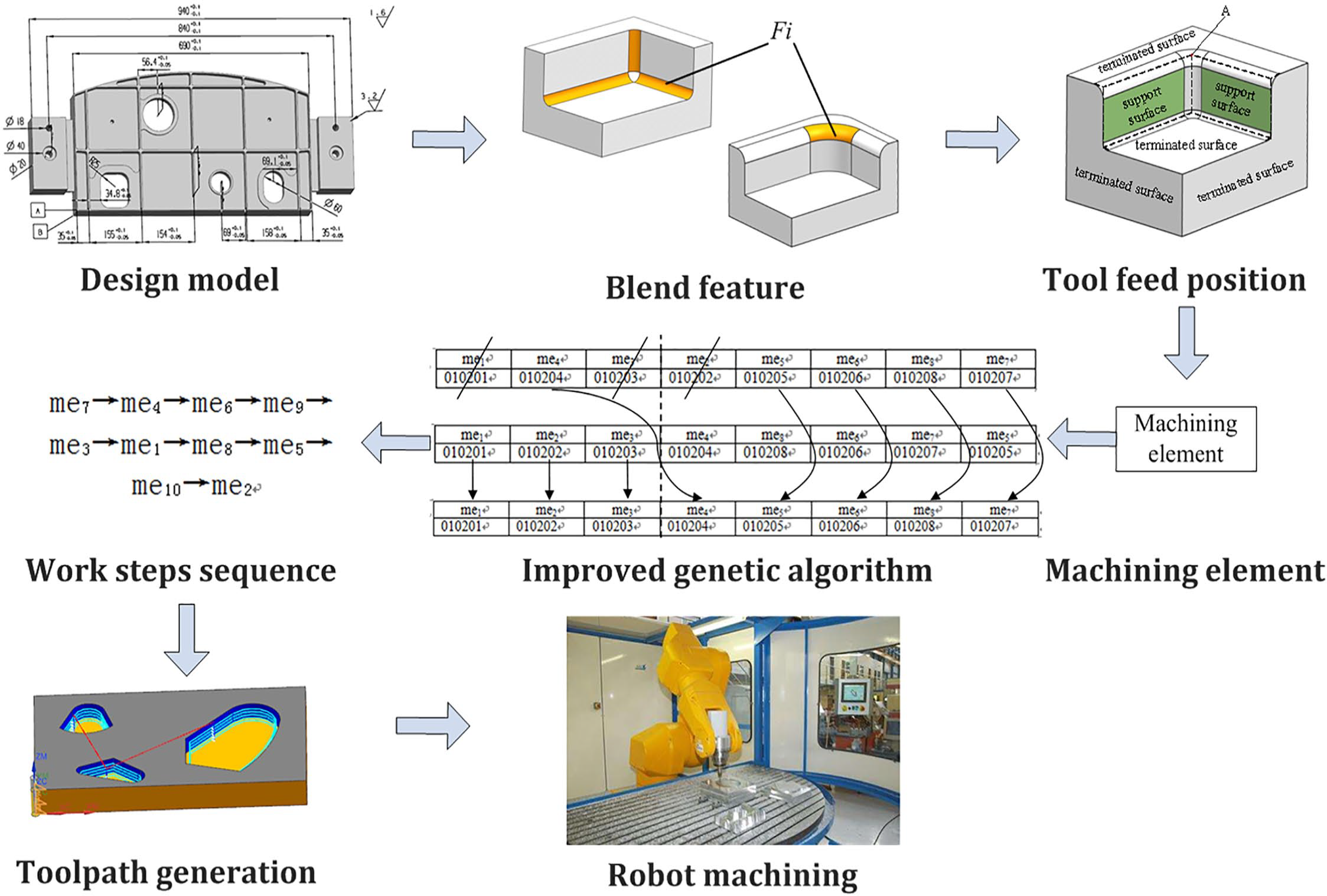
Flow chart of robot tool path planning based on BFS.
This article focuses on the influence of blend features on the robot tool path planning of multi-cavity parts. The rest of this article is structured as follows: section “Geometrical background” describes the geometrical background. Algorithm modeling of BFS is presented in section “Algorithm modeling of BFS.” In section “Robot tool path optimization using BFS,” we describe an improved-GA algorithm, which is used to optimize the tool path of multiple cavities. Section “Case study” contains a case study and discussions to prove the proposed method. The article ends with conclusions and identified areas for future research.
Geometrical background
Cavity features are commonly found in aircraft structures and mold designs, which are usually formed by four cavity walls and a cavity bottom. An aircraft’s fuselage frame is a typical multi-cavity structure. To satisfy safety and machinability requirements, and to avoid corner stress, which is generated by the concentration of cracks, blend features are used to replace sharp edges or sharp corners, as shown in Figure 2.
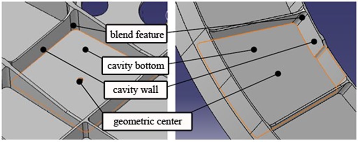
Blend features in aircraft cavity part.
In general, blend features are the intersection of two planes or multiple planes, using arc surfaces instead of their intersections. Blend features usually include a cylindrical surface, spherical surface, ring surface, and B-spline surface, as shown in Figure 3.

Blend feature types: (a) cylindrical surface, (b) cylindrical surface, (c) cylindrical surface, (d) spherical surface, (e) ring surface, and (f) B-spline surface.
The existence of the blend feature changes the original cavity structure, and the original linear boundary becomes a curved surface, which makes it difficult to obtain the coordinates of the tool feed position. The key to eliminating blend feature interference is to reconstruct the linear boundary of the cavity without changing the geometric elements of the blend feature. Different types of blend features contain different geometric elements (points, lines, surfaces, etc.). Table 1 describes the geometric elements of different types of blend features.
Geometric elements of blend feature.

Transitional surface refers to the smooth arc surface of the blend feature, including transitional surface of the boundary type and transitional surface of the point type. Boundary transitional surface refers to the curved surface formed by rounding the sharp edge. Point transitional surface is an arc surface formed by the intersection of two or more edged transitional surfaces, which are used to replace the point of intersection formed by the intersection of the sharp edges, as shown in Figure 4(a).

Geometric elements of blend feature: (a) blend surface and (b) geometric elements.
The key to successful cavity tool path planning is to obtain the machining feature boundary, which includes the geometric elements shown in Figure 4(b). The supportive surface of the blend feature contains the boundary line of the blend feature, which is contiguous with the arc face. The terminate surface of the blend feature contains the sharp edge of the arc of the blend feature and it is contiguous with the arc face. The boundary line of the blend feature is the curve formed by the extension of the supportive surface, denoted as £. If £ is closed, then £ is a simplified transitional curve representing the true machining boundary. Otherwise, £ is a curve representing the direction of the machining boundary.
Algorithm modeling of BFS
From a geometric point of view, when we process the cavity in the machining allowance that has been determined, the calculation of the tool feed position is the key to robot programming. Due to the interference of blend features, in the actual calculation process, we must calculate the tool feed position (point A, as shown in Figure 4(b)) according to the blend feature’s radius. In order to simplify the calculation process, and accurately obtain the coordinates of point A, we reconstruct the blend feature’s line segment £, which can be divided into two categories: (1) line segment of the boundary blend feature and (2) line segment of the point blend feature. BFS can also be divided into two types.
BFS for boundary blend feature
The supportive surfaces of the blend feature are extended to intersect. After the intersection is complete, the terminated surface is truncated to obtain £ of the blend feature. Due to supportive surface loss (Figure 3(b) and (c)) or fading (Figure 3(f)) often occurring in blend features, it is more difficult to reconstruct £. Therefore, the supportive surface is replaced by an auxiliary plane.
BFS for point blend feature
From the viewpoint of boundary changes, no matter how complicated the topological boundary of the point blend feature is, the extension lines of its related edges on the surrounding supportive surfaces are always intersected. Based on this principle, the feature line segment of the point blend feature’s surface is mainly obtained by extending the corresponding feature line segments of the adjacent side transition surface to intersect. A flow chart depicting this is shown in Figure 5. The reconstruction algorithm for £ is as follows:
Step 1. Select the blend feature in the 3D geometric model.
Step 2. If the blend feature has point transitional surfaces, then execute Step 3. If the blend feature has boundary transitional surfaces, execute Step 4.
Step 3. Get all transitional surfaces of point blend features.
Step 4. If the supportive surface of the boundary blend feature does not exist, execute Step 5. If the supportive surface of boundary blend feature exists, execute Step 6.
Step 5. Build auxiliary planes.
Step 6. Extend the supportive surfaces to intersection, and the resulting intersection is the blend feature line £, as shown in Figure 4(b).
Step 7. If the blend feature line is a closed curve, then the blend feature line segment is £. If the blend feature line is a non-closed curve, execute Step 8.
Step 8. If the adjacent surface of the blend feature line is the point transitional surface, go to Step 9. If the adjacent surface of the blend feature line is not point transitional surface, return to Step 3.
Step 9. Use the extension surface of the terminated surface to intercept the blend feature line £ to form the blend feature line segment £, as shown in Figure 4(b).
Step 10. The intersection of the terminated surface and £ is point A, as shown in Figure 4(b).

Flow chart of the blend feature line segment reconstruction.
The steps involved in Step 5 to build the auxiliary plane are as follows:
Step 5.1. Select e1 and e2 of the boundary transitional surface, as shown in Figure 6(a), as the reference boundary.
Step 5.2. The surface normal of the transitional surface at any point on the boundary e is the surface normal of the supportive surface of e, and the normal vector must cross the corresponding centroid of the transitional surface to determine the surface normal vector n of the auxiliary surface, as shown in Figure 6(b).
Step 5.3. Reconstruct the missing support plane using the reference boundary e and the surface normal n, as shown in Figure 6(c).
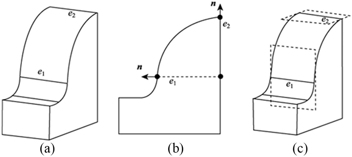
Auxiliary plane construction: (a) select datum boundary, (b) vector n of the auxiliary surface, and (c) construct auxiliary plane.
Based on the BFS, we can obtain the coordinates of the robot tool feed point (Point A, as shown in Figure 4(b)), which can be used to inform the automatic decision-making and optimization of the multi-cavity work step sequence.
Robot tool path optimization using BFS
In the machining process of multi-cavity parts, we can obtain the coordinates of tool feed position using BFS. On this basis, if we calculate the optimal path between different tool feed positions, the optimal robot tool path can be determined. To realize the automatic decision-making and tool path optimization for multi-cavities, we define the concept of a machining element. A machining element is the smallest unit that describes the machining of features. This includes information related to features, methods, manufacturing resources (such as robots, fixtures, and measuring tools), cutting parameters, and tool movement mode. The mathematical expression for the machining element can be expressed as

where fi is the machining feature, MPi is the machining method, MRi is the manufacturing resource and cutting parameter; TAD refers to tool approach direction, which means tool movement mode, and Ai(x, y, z) are the coordinates of tool feed position, which can be obtained by BFS.
The entire machining element set of a part can be expressed as

As the optimization variables of ME are not numerical values, but mathematical arrangements, their constraints cannot be expressed by explicit mathematical modeling. It is difficult to obtain the optimal tool path using conventional optimization rules and algorithms.21,22 GAs do not directly use numerical values as operands, but express variables in the form of genetic code and then optimize them. 23 Through genetics, crossovers, and mutations, it is possible to search for the optimal sequence combination of the worldwide genetic code, which offers the advantage of high parallelism and strong robustness. 24 Therefore, it is more appropriate to use a GA to solve the optimization problem of a tool path. However, due to the large amount of computation involved in traditional GAs, it is easier to prematurely converge to form a local optimal solution. In the engineering application process, this is often combined with the features of optimized objects, with improved GAs (multi-population GA, single parent GA, elite retention, etc.) being used to solve these practical problems.25–28
The principle idea of the elite retention strategy is that elite individuals who appear during stages of the evolution process of the group are no longer paired with other individuals and are directly copied to the next generation. At the same time, in order to ensure that the size of the group does not change, if elite individuals are added to the next-generation group, the least-adapted individuals in the group will be eliminated, while the “survival of the fittest” among genetic individuals will be achieved. In this genetic process, we try to ensure that elite individuals reproduce in the next generation of populations. Following the natural law of survival of the fittest, this can effectively avoid the loss of optimal individuals during the next generation, resulting in the GA being unable to converge to the global optimal solution. Therefore, we use GA based on elite retention strategy to optimize the tool path. The basic flow of the algorithm is shown in Figure 7.

Flow chart of genetic algorithm.
Initial population construction method
The iterative computation of GAs is based on the population P(t) (t stands for genetic algebra) consisting of chromosome set. The initial population size is generally represented by N. The value of N is based on actual experience and test guidance and typically ranges from 20 to 100.
Machining time calculation based on BFS
For robot machining, the machining time typically includes cutting time and machining assistance time. Among them, the machining-aided time refers to the tool change time, the tool idle stroke time, and the workpiece transposition time. For a single cavity’s tool path, the cutting time is fixed. Therefore, when the optimization objective function is established, only the machining assistance time is needed. Based on the aforementioned analysis, an objective function for optimization is established to shorten the machining assistance time

where T is the assistant machining time, n is the number of work steps, and ti is the ith cavity assistant machining time.
The formula of ti is

where n is the number of cavities, t1i is the workpiece transposition time, t2i is the tool change time, t3i is the tool idle stroke time, Pi is the machining orientation code corresponding to the ith cavity tool path, and Qi is the tool’s code corresponding to the ith cavity tool path.
When the machining positions Pi of two consecutive cavities are the same, the workpiece does not need to be transposed, therefore, t1i is zero. When the machining positions are different, the workpiece transposition time needs to be recalculated. When two consecutive cavities use the same tool, the tool does not need to be replaced, then the tool change time t2i is zero. When using different tools, the tool change time needs to be calculated. Therefore, formula (4) satisfies the conditions as follows

In formula (4), the t3i is directly related to the distance between different cavities, which can be calculated by Ai(x, y, z)

where Ai(x, y, z) is the tool feed position of ith cavity, which can be obtained by BFS. vf is the tool speed of idle stroke.
Determination of fitness function
The fitness function is used to measure the individual’s merit in GAs. The fitness size determines whether a genetic individual breeds or dies. The greater the individual’s fitness, the better it is. Usually, the fitness function is obtained by converting the objective function, both of which should have positive values and the same extreme points. Based on this principle, the fitness function is expressed in conjunction with formula (3) as

Selection and copy operations
The elite individuals selected in conjunction with the elite retention strategies do not cross-operate with other individuals and are directly added to the next generation through replication. At the same time, individuals with the lowest fitness are eliminated from the next generation and the number of groups remains unchanged. Elite individuals generally use fitness as the measurement standard. The number of elite retention in each generation is controlled by the replication probability Pr. The range of Pr is generally set to 0.1–0.2.
Crossover operator
Crossover is the main method for generating new individuals in GAs (the principle is similar to hybridization in the field of biology). The number of chromosomes that perform crossover operations is usually controlled by the crossover probability Pc, while the range of Pc values is generally set to 0.5–0.8. Crossover methodologies include single-point intersections, two-point crossings, and circular crossings. In this article, considering the rationality of the initial work steps sequence and to avoid destroying the potential high-quality gene fragments, a single-point crossover algorithm is used, as shown in Figure 8. The steps taken are as follows:
Step 1. According to the method shown in Figure 8, P1 and P2 are arranged as the parent chromosomes for performing the cross operation.
Step 2. An intersection is randomly generated, dividing P1 and P2 into two segments: left gene segment and right gene segment.
Step 3. Copy the left part of the parent P1 intersection to the individual C1 of the offspring to form the left half of the C1 gene fragment.
Step 4. Delete the same gene in the parent P2 as that in the parent P1. The remaining genes are copied to the child C1 in the order of P2, forming the right half of C1, and generating the complete child C1.

Single cross generation of offspring chromosomes.
Mutation operator
The number of chromosomes that produce mutations is typically controlled by the mutation probability Pm. The range of Pm values is generally set to 0.01–0.1. The conversion operation steps are as follows:
Step 1. According to the method shown in Figure 8, a reasonable initial work step sequence P1 is arranged as the chromosome for performing the mutation operation.
Step 2. Assume that the chromosome length is n, and randomly generate two natural numbers as mutation points in the interval [1, n].
Step 3. Exchange the two sets of genes at the mutation site to generate a new chromosome P2.
Step 4. According to the work step constraint rule, P2 is checked for validity. If it is valid, P2 is used as a descendant group for subsequent calculation; if it is invalid, return to Step 2.
Termination conditions
There are two termination conditions commonly used in GAs: (1) set the number of iterations N. When the number of iterations of the algorithm reaches the specified value, the operation terminates; and (2) when several iterations are performed and the optimal individual’s fitness does not change significantly, the operation terminates.
Case study
To verify the effectiveness of the proposed method described in this article, the robot tool path planning of an aircraft structural part (shown in Figure 9) is used as an example. The processing of this part mainly involves the milling of 16 cavities (Ra = 6.3); each cavity corner adopts fillet transition. In this case, the machining accuracy is not high, so a robot or five-axis machine tool milling can be used. Considering the deformation during processing, a robot with a large load and rigidity is required.
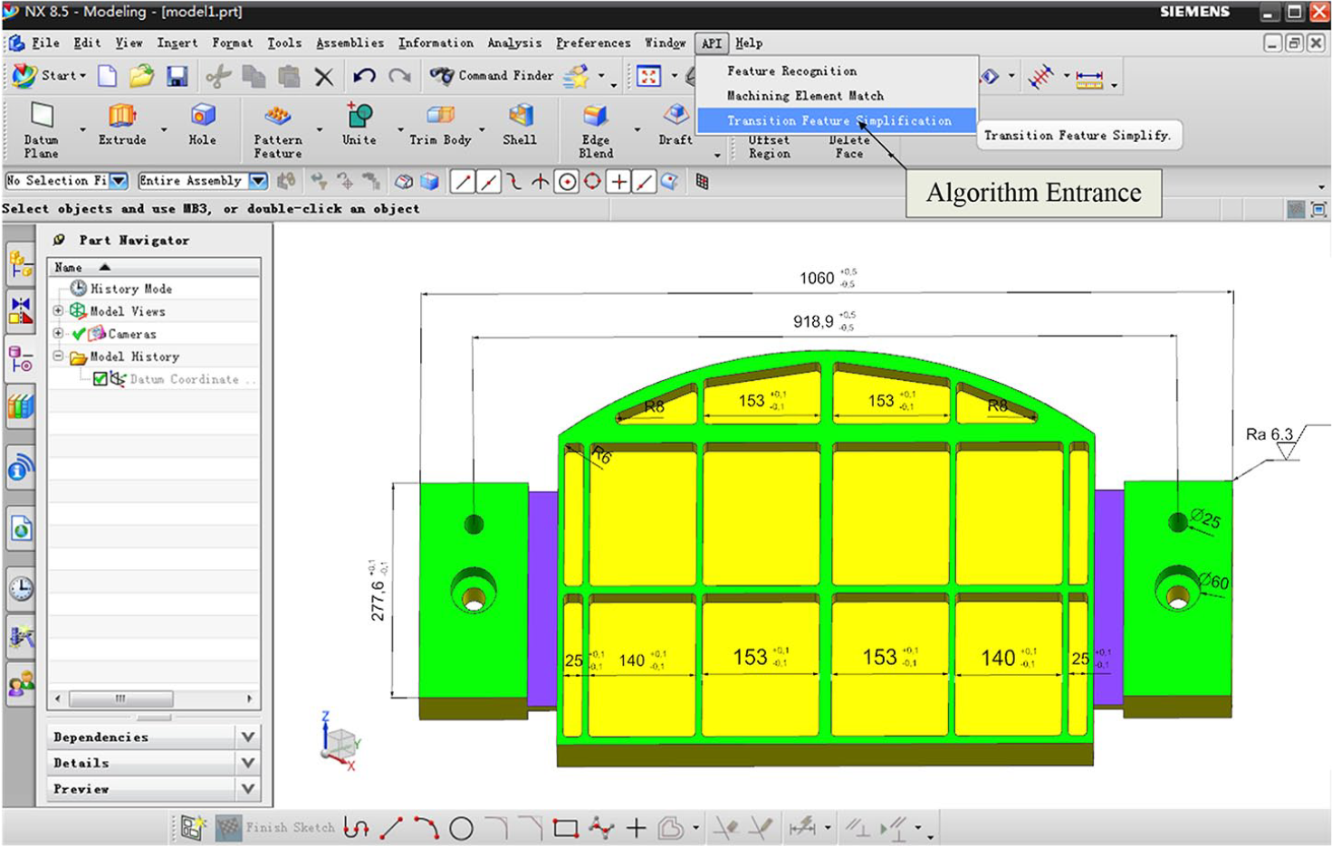
Multi-cavity model of an aircraft structural part.
The method described in section “Algorithm modeling of BFS” is used to simplify the blend features and efficiently obtain the tool feed positions of different cavities. We make use of the application programming interface that NX provides and carry on the secondary development to NX8.5, which realizes the BFS algorithm, as shown in Figure 9.
According to the number of cavities in the part, the number of corresponding machining elements is 16. According to the method described in section “Robot tool path optimization using BFS,” machining elements represent a parent entity in the initial population. Combining the blend features of the cavities and BFS algorithm, we obtain the tool feed position of 16 machining elements, as shown in Figure 10.

Machining element location (tool feed position).
Combined with the 3D model as shown in Figure 10, the information of the generated parent entity P1 is shown in Table 2.
Initial population chromosome.

As a means for achieving the comparison verification, we tested three different tool path simulation motions. The first tool path followed cavity centroid, shown in Figure 11(a). Figure 11(b) shows the second tool path, which is zigged with contour. Figure 11(c) shows the trochoidal tool path, which follows cavity center. Figure 11(d) shows the tool path simulation motions, based on BFS.

Tool path simulation: (a) follow cavity centroid, (b) zig with contour, (c) follow cavity centroid with trochoidal, and (d) tool path planning based on BFS.
For the tool path planning, built on BFS, if the calculation is based on the mathematical total alignment method, theoretically, the maximum evolution algebra (possible number of step sequences) is M = 16! In order to reduce the amount of calculations required, we set three different maximum evolution algebras to M = 100, M = 50, and M = 35 times as the termination condition of the algorithm. When the number of iterations reached the maximum evolution algebra, the algorithm was automatically terminated. We used MATLAB to iteratively calculate the sample, comparing the results of the conventional GA with the improved-GA, as shown in Table 3. Table 4 shows the machining time required to use these three different tool paths.
Comparison of conventional GA and improved GA.

GA: genetic algorithm.
Comparison of three tool path results.

BFS: blend feature simplification.
Upon comparing the computed results of the conventional GA with the improved-GA, we are able to obtain the following results:
In this experiment, when the terminate conditions (maximum evolution algebras) are set to M = 50, M = 35 times, we cannot obtain the optimal results in the maximum evolution algebras by using the conventional GA. On the contrary, the convergence rate of improved GA is faster and the convergence algebra is much smaller than the largest evolutionary algebra. Through analysis, we can see that the improved-GA algorithm, used in this article, has high computational efficiency.
Since the parent P1 selected in this calculation has a good genetic gene, theoretically, according to the elite retention principle, the convergence algebra should be within (16–16 × 50%)! = 40,320 generations. The calculation results show that the convergence algebra is far less than the theoretical value, which proves the superiority of the proposed GA algorithm.
The tool path method, based on BFS, can locate the optimal solution within the specified maximum evolutionary algebra to achieve the goal of optimizing the tool path. By combining Table 4, it can be calculated that the machining time of BFS is 10.08% faster than following cavity centroid, 19.38% faster than zig with contour, and 11.7% faster than trochoidal path.
Conclusion and future work
In this article, we have proposed and validated a robot tool path planning method, based on BFS. Some of the main contributions of this research are listed here.
The machining element is proposed to describe the work step decisions. Considering the influence of the blend feature on the position of the tool in-feed, we designed a BFS algorithm to accurately obtain the tool feed position. On this basis, the spatial distance between different cavities can be calculated automatically. This makes tool path planning for cavity machining more convenient.
An improved-GA is used to find the optimal tool path. The results show that compared with other three common methods the approach proposed in this article can shorten more than 10% machining time.
As blend features may exist at different corners of a cavity, as demonstrated in the example used in this article, manual intervention is often required to select the blend features to be simplified. The tool path planning is ultimately a combination of artificial experience and artificial intelligence algorithms. Although this approach reduces the intelligence of the decision-making process, it greatly reduces the computational complexity of the algorithm and improves the decision-making efficiency and enhances the practicality of the method.
The algorithm is equally applicable to five-axis machining machines. However, for the multi-cavity machining programming with blend features, as described in this article, the robot machining planning has more advantages than traditional numerical control (NC) programming. First, the offline programming software for the robot can automatically identify and search the CAD model for point, line, and surface information to generate tracks. By combining the BFS algorithm described in this article, the tool feed position can be more accurately and quickly obtained. Second, the trajectory is associated with the CAD model features; if the model moves or deforms, the trajectory will change automatically.
In order to further improve the intelligence of the decision-making process, follow-up research should consider improvement of the algorithm. Future work is also planned to extend and improve the prototype system by intelligently screening the feed position of blend features.
Footnotes
Declaration of conflicting interests
The author(s) declared no potential conflicts of interest with respect to the research, authorship, and/or publication of this article.
Funding
The author(s) disclosed receipt of the following financial support for the research, authorship, and/or publication of this article: This work was partially supported by the Scientific and Technological Innovation Projects in Shanxi Universities (Grant No. 201802027), the Key Laboratory of Road Construction Technology and Equipment of MOE (Chang’an University; Grant Nos 300102259514 and 310825171004), the Natural Science Basic Research Project of Shaanxi Province, China (Grant No. 2019JM-073), the China Postdoctoral Science Foundation (Grant No. 2018M633439), and the National Natural Science Foundation of China (Grant Nos 51705353 and 51805043).