
Abstract
The surrounding rock may become unstable or even fall down and the initial support may crack and be destroyed when the construction method of the underground excavation tunnel is not properly selected in the turn line of metro.
Introduction
There will inevitably be a small interval tunnel in the turn line of metro in the process of urban subway construction. The turn line has a complicated force condition for the tunnel with a small interval, and the process has great influence on each other during construction.1–5 Therefore, the surrounding rock may become unstable or even fall down and the initial support may crack and be destroyed when the construction method of the underground excavation tunnel is not properly selected.6–11 It is key to ensure tunnel construction safety to simulate the construction process of a small interval tunnel in the turn line of metro,12–16 analyze the rationality of the proposed construction method, and predict the surrounding rock and initial support stress and deformation and possible damage parts.
The surrounding rock is subjected to multiple excavation disturbances, and the mechanical effects are complicated during the construction of a small interval tunnel in the turn line of metro.17–19 Engineers and scholars have studied the reasonable thickness of the rock pillars in the small interval tunnel, the reinforcement measures of the middle rock pillars, and the construction procedures to ensure the safe construction and reduce construction risks. Ghabornssi and Ranken 20 studied the influence of the minimum interval of the tunnels on the stability of the middle rock pillars and pointed out that the deformation and stress of the middle rock pillars caused by the excavation of adjacent tunnels when the minimum interval of the tunnel is greater than 2 times of the tunnel diameter changes can be ignored. Hefny 21 found out that the tunnel excavation disturbance has a significant impact on the lining stress and the surrounding rock stability of the preceding tunnel when the minimum interval is less than the tunnel diameter through the physical model test and numerical simulation.22,23 By means of the model test, Huo et al. 24 studied the surface settlement control technology of the small interval under a weak surrounding rock and determined the reinforcement measures. Song et al. 25 studied the law of the surface settlement in the parallel double tunnel. Zheng et al. 26 compared the stress of the surrounding rock and the internal support force in the small interval tunnel with the bench cut method and the center cross diaphragm (CRD) method. Wang et al. 27 studied the ground deformation caused by small interval tunnels and established a calculation model for surface settlement. Ng et al. 28 found that the distance between the leading tunnel and the back tunnel face is the main factor affecting the horizontal convergence, but has little effect on the change of the arch settlement.
According to the abovementioned literature review, there are many researches on the reinforcement measures of the rock pillars and surface settlement in the small interval tunnels, and the research on the influence of the construction processes is relatively rare. There is no uniform understanding of the reasonable spacing between the leading tunnel and the back tunnel face. Therefore, this article takes a section of the Santunbei turn line tunnel of Urumqi Metro Line 1# as a case. The reinforcement method of the middle rock pillars and the tunnel excavation method were carried out. The numerical analysis of the proposed tunnel construction method was carried out to predict the maximum surface settlement and horizontal convergence caused by tunnel excavation. Finally, the deformation and force analysis of the six construction methods are analyzed and compared to provide reference for the construction of similar tunnel projects.
Tunnel overview
The CDK0+214∼CDK0+264 of Urumqi Metro Line 1# is the turn line, and the interval is ultra-small distance tunnel. The tunnel support parameters are shown in Figure 1.
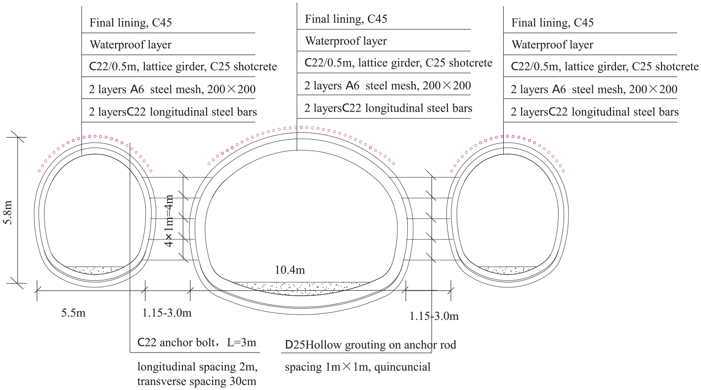
Tunnel support parameters.
The tunnel interval is gradually changed from 1.15 m to 3.0 m, as shown in Figure 2(a). The tunnel construction is carried out by the CRD+bench cut method. The main tunnel of the turn line is constructed by the CRD method, and the left and right tunnels of the single line entrance and exit line are constructed by the bench cut method. The interval is small, and the disturbance of each construction procedures is large. The distance (L) between the left and right tunnel face was set as 5 m to reduce disturbance during tunnel construction.

Construction method: (a) Excavating sequence; (b) The distance (L) between the left and right tunnel face; (c) Construction space between left and right tunnel face.
A monitoring section is arranged for every 10 m of surface settlement, as shown in Figure 3(a). Figure 3(b) shows the vault sinking and convergence, monitoring point A represents the vault settlement monitoring, and monitoring point B represents the convergence monitoring. The displacement measurement points are arranged at the position of the middle rock pillars to understand in detail the displacement variation law of the rock pillars between the tunnels during the tunnel construction process, as shown in Figure 3(c).

Layout of the small interval tunnel section, middle rock pillars, and measurement points in the tunnel (A, B): (a) Monitoring points of Surface settlement; (b) Monitoring points of vault displacement and convergence; (c) Displacement monitoring points of the middle rock pillars.
Numerical simulation results and verification
The numerical simulation of the tunnel construction process is carried out to analyze whether the proposed tunnel construction method is reasonable, assess stress and deformation of the surrounding rock and initial support structure, and predict the parts that may be damaged.
MIDAS/GTS software was used for numerical simulation. The stress–strain curves of the surrounding rock adopts the Mohr–Coulomb criterion, and the three-dimensional finite element model is shown in Figure 4. The surrounding rock was simulated with mixed hexahedral units, the initial support was simulated by an elastic plate unit, and small forepoling was simulated by a one-dimensional elastic implanted truss unit. The grid size of the small interval tunnel, the initial support, and the tunnel structural unit is 1.0 m, the grid size of the surrounding rock unit is 3 m, and the model has a total of 67776 units and 43081 nodes. The distance from the bottom of the tunnel to the bottom boundary of the model is 3D, and the length (Y-axis) and width (X-axis) of the model are 1.5 (H+3D) and H+3D, respectively, where H is the tunnel depth and D is the tunnel width. The length, width, and height of the model are 160 m × 80 m × 50∼60 m respectively, and the tunnel depth is 13∼20 m. The overburden cover on the tunnel is 11.3 m, the thickness of the greatly weathered sandstone is 6 m, and the thickness of the moderately weathered mudstone is 41 m. The upper surface of the model is a free surface; the X-direction displacement constraint is applied to the left and right sides; the Y-direction displacement constraint is applied to the front and back sides; and the solid-end constraint of the X, Y, and Z directions is applied to the lower surface. The material parameters used in the numerical simulation of the tunnel are shown in Table 1.

Small interval tunnel model.
Material parameter of the model.
Numerical simulation results
Surface settlement
According to the numerical analysis results, the surface settlement of the tunnel at the CDK0+214 and CDK0+224 is the largest during the excavation process. The monitoring section at the boundary of the model may be affected by the boundary conditions. Therefore, the section CDK0+224 is selected to analyze the variation law of surface settlement at each stage. The surface settlement curve of each stage is shown in Figure 5.

Surface settlement curve.
There is little change in surface settlement after the construction of the lower stage on the left side of the tunnel. During the construction of the left and right tunnels, the peak of ground settlement remains at the top of the right tunnel; at the right construction stage of the main tunnel, the peak point gradually moves toward the main tunnel vault. After the left side of the main tunnel, the peak of the ground settlement moves to the main tunnel arch. Before the construction of the main tunnel, the surface settlement value is less than 0.5 mm; the final stability value surface settlement after the construction of the main tunnel is 2.5 mm; it indicates that the surface settlement caused by the excavation of the left and right tunnels is small, and the surface settlement value is mainly caused by the excavation of the main tunnel. However, the final settlement value is less than 3.0 mm, which can ensure the normal operation of the surface road.
Initial support arch settlement and horizontal convergence
The CDK0+224 arch settlement curve is shown in Figure 6.

Settlement curve of the tunnel vault.
When the right tunnel and the left tunnel upper stage face are about 8.0 m away from the monitoring section, the monitoring point will produce vertical displacement. After the tunnel face passes the monitoring surface, the deformation of the tunnel vault tends to be stable for the first time when the monitoring surface is about 10 m. At this time, the settlement deformation of the tunnel vault is about 1.0 mm. During the construction of the main tunnel, the second deformation of the tunnel vault occurred, and the settlement value of the vault increased by about 0.5 mm, accounting for 1/3 of the total settlement. When the main tunnel face is about 11 m away from the monitoring surface, the main tunnel arch begins to settle vertically; when the face is 23 m through the monitoring section, the vertical displacement of the main tunnel tends to be stable. The displacement of the main tunnel caused by the excavation of the left and right tunnels is about 0.2 mm, and the vertical displacement of the vault of the main tunnel caused by the excavation of the main tunnel is 3.0 mm. According to the abovementioned analysis, the vault settlement curve of the left and right tunnel is affected by 1.5d behind the face and 2d ahead of the face; the deformation curve of the main tunnel is affected by 1d behind the face and in front of the face. The tunnel arch is heavily affected by the main tunnel, but the main impact comes from the tunnel excavation.
Figure 7 shows the convergence curve of the initial support at the monitoring section CDK0+224. When the right tunnel is constructed, the convergence increases sharply, and the convergence of the right tunnel shrinks into the tunnel, while the convergence of the left tunnel and the main tunnel expands out of the tunnel. It indicates that the left tunnel and the main tunnel have a displacement to the right tunnel. When the left tunnel is constructed, the convergence of the left tunnel and the main tunnel is further expanded outside the tunnel, and the convergence of the right tunnel remains unchanged. During the construction of the main tunnel, the convergence deformation of the right tunnel, the main tunnel, and the left tunnel is expanded outside the tunnel. The main tunnel construction has less influence on the convergence of the main tunnel and more influence on the convergence of the left tunnel and the right tunnel. When the tunnel excavation passes through the monitoring cross section, there is a sudden change in the convergence. It results in the selection of the measuring point at the junction of the upper and lower stage, but this does not affect the tunnel convergence result.

Convergence curve of the initial support.
Displacement analysis of the middle rock pillars
Figure 8 is the transverse displacement curve of the middle rock pillars (positive values represent the tunnel tensile and negative values represent compression). The lateral deformation measurement point of the left rock pillar only shows a sudden change in the left tunnel construction and the main tunnel construction phase, and there is little change in the right tunnel construction phase; the lateral deformation point of the right rock pillar is only in the right tunnel construction and there is a sudden change in the construction phase of the main tunnel. There is little change in the construction phase of the left tunnel, indicating that the plastic deformation of the rock mass is only related to the construction of the adjacent tunnel. After the tunnel construction is completed, the cumulative lateral deformation of the left rock pillar is higher than that of the right rock pillar.
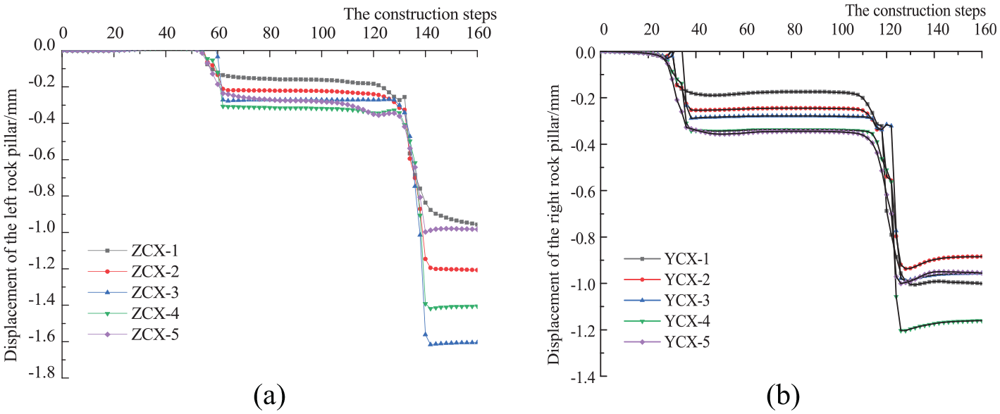
Middle rock pillar displacement on the right side: (a) Displacement of the left rock pillar. (b) Displacement of the right rock column.
The lateral displacement of each abrupt phase during tunnel construction is shown in Table 2. The second-stage lateral displacement of the middle rock pillars is significantly higher than that of the first-stage lateral displacement, indicating that the displacement of the middle rock pillars is affected more by the main tunnel construction than the side tunnel construction. In the second sudden phase, the lateral displacement is higher than the displacement of the middle rock pillars, and the left middle rock pillars are more sensitive to the influence of the main tunnel construction. The lateral displacement of the left rock pillar is higher than that of the right rock pillar, indicating that the plastic deformation zone of the left rock pillar is larger than the right rock pillar.
Lateral displacement of the rock pillar/mm.

The displacement of the left middle rock pillar is larger than that of the right rock pillar. The displacement law of the left middle rock pillar is used to analyze the deformation trend of the rock pillar during the construction of the small interval tunnel. The lateral displacement curve of the measuring point of the left rock pillar is shown in Figure 9 (“+” value means moving to the right and “–” value means moving to the left).

Left rock pillar displacement.
During the construction of the tunnel, the lateral displacement of the left measuring point of the rock pillar on the left side of the monitoring section is only negative during the construction of the left tunnel, and the other phases are positive, indicating that the left side of the left rock pillar moves to the right. The lateral displacement curve of the right measuring point of the left rock pillar is during the construction of the right tunnel. Due to the removal of the right soil, the stress is released, the measuring point moves to the right, and the curve is in an increasing trend. The point gradually moves to the left side, and the accumulated deformation amount is negative after stabilization, indicating that the deformation amount of the left tunnel construction stage is higher than that of the right tunnel construction stage. During the construction phase of the right part of the tunnel, the measuring point moved to the right side again, and the cumulative displacement and deformation changed from negative to positive. In the construction stage of the left part of the main tunnel, the cumulative displacement of the right measuring point of the left rock pillars decreases to some extent. The lateral displacement of the left side of the rock pillar is positive, and the lateral displacement of the right side is negative, indicating that the left rock pillar is in a compressed state during tunnel construction.
Analysis of initial support stress
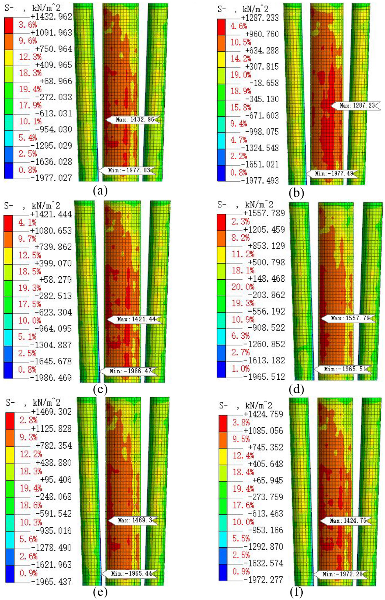
Figure 10 shows the maximum principal stress distribution of the initial support at each characteristic stage during tunnel construction (“+” is the compressive stress and “–” is the tensile stress). At the initial stage of tunnel construction, the support is only subjected to compressive stress. As the construction support of the tunnel is subjected to compressive stress and tensile stress, the peak compressive stress and tensile stress are 5066.13 kPa and 1977.49 kPa, respectively. The tensile stress decreases and the compressive stress rises during the construction of the main tunnel to the left lower step until the construction of the main tunnel is completed. After the construction of the tunnel, the support is closed and formed into a ring with symmetrical force and no stress concentration. It shows that the construction of tunnel support in time can improve the stress capacity of the structure obviously. When the soil of the main tunnel is removed, the lateral displacement trend increases, the deformation of the arch waist position gradually increases, and the tensile stress of the support increases. The peak tensile stress increase of the support in the construction stage on the left side of the main tunnel is the largest, with an increase of 2460.08 kPa (130.6%). The support of the upper stage in the left part is not closed to form a ring, and the construction of the left tunnel brings about the failure to support the new air surface in time, and the stress concentration phenomenon appears in the position of the support at the top of the right side of the main tunnel. The peak compressive stress increment of the support in the construction stage of the lower right step of the main tunnel is the largest, with an increase of 669.68 kPa (90.0%). The reason for this phenomenon is that all the soil in the right part of the main tunnel is removed, a new air surface appears on the right side of the right rock pillar, and the movement of the rock pillar to the right side produces a rightward support. The lateral partial pressure causes a high compressive stress on the right side of the right branch of the right tunnel.

Maximum principal stress of initial support: (a) Upper stage of the right tunnel. (b) Lower stage of the right tunnel. (c) Lower stage of the left tunnel. (d) Upper stage of in right of the main tunnel. (e) Lower stage of in right of the main tunnel. (f) Upper stage of in left of the main tunnel. (g) Lower stage of in left of the main tunnel. (h) Finish.
Monitoring and verification
Monitoring of vault displacement and surface settlement
The vertical displacement curves of the CDK0+214, CDK0+224, CDK0+234, CDK0+244, CDK0+254, and CDK0+264 vaults of the tunnel are shown in Figure 11(a)–(c). The deformation curves of each measuring point are almost the same. During the whole construction process, the deformation of the right tunnel arch is abruptly changed in the tunnel construction on the right side and the CRD construction of the main tunnel; the deformation of the vault of the left tunnel is abrupt in the construction of the left tunnel by the CRD method of the main tunnel; the deformation of the main tunnel vault is abrupt only during the construction of the main tunnel itself by the CRD method. The maximum settlement value is 4 mm, which meets the specification requirements (20 mm).
After the construction of the tunnel section is completed, the vertical displacement curve of each measurement point on the surface is shown in Figure 11(d). Sections 1∼6 correspond to the section mileage CDK0+214∼CDK0+264, and the section of CDK0+214 has the largest width of the rock pillar and the largest construction span. The surface displacement of CDK0+214 is the largest, and the maximum surface measurement is 4 mm. The maximum deformation is controlled within 30 mm, which meets the normal driving requirements of the surface road. The peak deformation of CDK0+214∼CDK0+264 in the section shows a decreasing trend, and the peak measuring point is almost stable near the axis position of the main tunnel; the deformation value of the measured data of each monitoring section is almost settled.

Curve of deformation and surface deformation: (a) Displacement of the right tunnel vault. (b) Displacement of the left tunnel vault. (c) Displacement of the main tunnel vault. (d) Surface deformation curve.
Comparison and analysis
Figure 12 shows a deformation contrast curve of the support at the position of CDK0+224∼254, and the monitoring data are consistent with the deformation law of the simulated data. In the main tunnel vault, the measured values of the displacement of the left tunnel and the right tunnel arch are lower than the simulated value, and the peak difference is 0.4 mm. The difference is small, and the numerical simulation results are reliable.

Deformation contrast curve at CDK0+224~254. CDK0+224: (a)Displacement of the left tunnel vault. (b)Displacement of the right tunnel vault. (c)Displacement of the main tunnel vault. CDK0+234: (a)Displacement of the left tunnel vault. (b)Displacement of the right tunnel vault. (c)Displacement of the main tunnel vault. CDK0+244: (a)Displacement of the left tunnel vault. (b)Displacement of the right tunnel vault. (c)Displacement of the main tunnel vault. CDK0+254: (a)Displacement of the left tunnel vault. (b)Displacement of the right tunnel vault. (c)Displacement of the main tunnel vault.
Figure 13 shows the surface displacement contrast curve of the support at the position of CDK0+224∼254. The measured data of the surface measuring points are consistent with the deformation law of the simulated data, and the settlement groove appears at the centerline of the tunnel.

CDK0+224~254 surface settlement curve.
Analysis of construction parameters
In order to further explore the deformation and stress variation of tunnels under different L, six different construction methods using L = 0, 5, 10, 15, 20, and 25 m were used to analyze tunnel deformation and stress. The distance between the upper and lower stage is 5 m, and the distance between the left and right sides of the CRD method is 15 m.
Comparison and analysis of surface settlement
Figure 14 shows the ground settlement curve of the section CDK0+224 after the construction of the different left and right tunnels. After the completion of construction, the maximum surface settlement is located at the top of the main tunnel, which is consistent with the variation law of the settlement tank. The influence range of surface settlement is about 56 m, and the maximum settlement value is lower than 3.00 mm, indicating that the construction using the six methods does not affect the normal operation of surface roads. The ground settlement curves of the six construction methods are almost coincident. When L = 5.0 m, the vertical displacement of the ground surface is slightly lower, which is lower than other construction methods by about 0.07 mm.
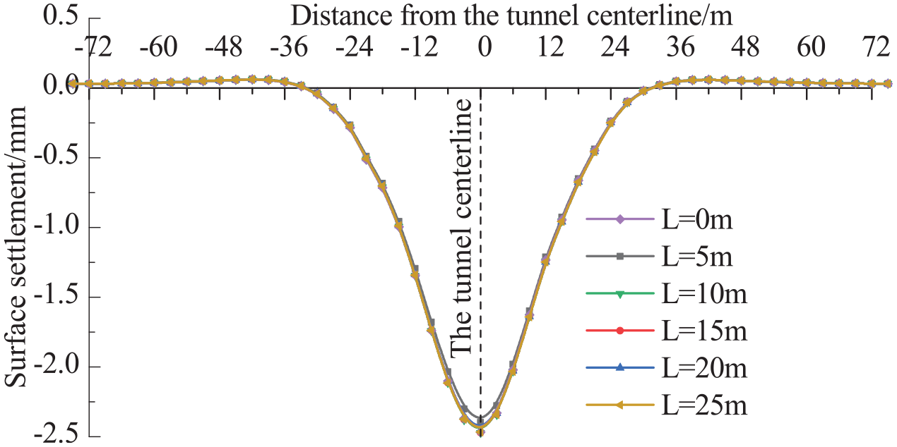
Surface settlement curve.
Comparison and analysis vertical displacement of initial support
The vertical displacement curves of the vault of the initial support of six construction methods at CDK0+224 are shown in Figure 15. The settlement values of the vault are shown in Table 3. The variation of the vault sinking curves of the six construction methods is the same. There is almost no difference in the final settlement value. When the construction spacing is L = 5 m, the vertical displacement of the left tunnel and the main tunnel arch is the smallest; when the construction spacing is L = 25 m, the vertical displacement of the right tunnel vault is the smallest, and the displacement of the main tunnel is the largest.

Deformation curve of the tunnel vault: (a) Deformation contrast curve of the left tunnel vault. (b) Deformation contrast curve of the right tunnel vault. (c) Deformation contrast curve of the main tunnel vault.
The final vertical deformation of the tunnel vault.

Comparison and analysis of convergence of initial support
Figure 16 shows the convergence curve of the initial support of the CDK0+224 section of the six construction methods (positive values represent the tunnel arch waist tension and negative values represent the arch waist compression), and the convergence changes caused by the various construction schemes are almost the same. After the completion of the construction, the convergence of the support of the six construction methods is shown in Table 4. When the construction spacing is L = 0 m, the convergence of the left tunnel and the main tunnel is the smallest. When the construction spacing is L = 5 m and L = 20 m, the convergence value of the right tunnel is the smallest. When the construction distance is L = 20 m, the convergence value of the main tunnel is the largest. However, the difference in the convergence values caused by the construction methods is very small, and they can be considered almost equal.

Convergence comparison curve: (a) Convergence of the left tunnel arch waist. (b) Convergence of the right tunnel arch waist. (c) Convergence of the main tunnel arch waist.
Convergence of initial support.

Comparison and analysis of the displacement of the middle rock pillar
Table 5 shows the horizontal displacement of the middle rock pillars in the six construction methods (positive values represent rock pillar tensile and negative values represent rock pillar compression). The displacement values caused by the six construction methods are approximately equal, and the deformation value is very small.
The lateral displacement of the rock pillar.

Comparison and analysis of initial support stress
The six main construction methods cause the maximum principal stress distribution of the initial support, as shown in Figure 17. There are differences in the maximum tensile stress peaks caused by the six construction methods. However, the maximum tensile stress peak position of the support after the completion of construction is maintained at the right side of the left tunnel. The maximum compressive stress peaks caused by the six construction methods are different, and the maximum compressive stress peak position of the support changes after the completion of construction, but the peak position remains at the main tunnel arch shoulder position. The peak stress of the initial support of the six construction methods is shown in Table 6. The support is subjected to a peak tensile stress of 1975±10 kPa, and the support is subjected to a peak shear stress of 2675±20 kPa. The shear stress and tensile stress of the six methods are approximately equal. When L = 5 m, the compressive stress of the support is the smallest. When L = 15 m, the compressive stress of the support is the largest, and the maximum compressive stress difference caused by the two methods is 270.2 kPa.
Initial support principal stress: (a) L = 0 m. (b) L = 5 m. (c) L = 10 m. (d) L = 15 m. (e) L = 20 m. (f) L = 25 m.
Initial support structure stress.

In summary, the deformation and stress of the leading tunnel will be affected by the post-construction tunnel, but the deformation and stress caused by the six construction methods are almost the same. It indicates that the construction spacing of the left and right tunnels will not affect the safety of tunnel construction. Therefore, the specific construction spacing can be selected according to the resource allocation, instead of the deformation and stress.
Conclusion
In this article, the small interval tunnel of the Santunbei turn line of Urumqi Metro Line 1# is taken as the engineering background, and the stress and deformation characteristics of the support and the surrounding rock in each stage of tunnel construction are numerically analyzed. Through the comparison and analysis of on-site monitoring data and numerical simulation results, it is found that the numerical model has certain rationality. Then, the surface settlement, the deformation of the middle rock pillar, and the deformation and bearing characteristics of the six construction schemes of L = 0, 5, 10, 15, 20, and 25 m are compared and analyzed. The conclusions are as follows:
When L = 5 m, the numerical simulation shows that the final surface settlement is 3 mm, the vault sinking is 3.5 mm, and the final convergence is 0.6 mm, which meets the requirements of subway tunnel construction specifications. Therefore, it is determined that the distance between the left and right tunnel of Urumqi Metro Line 1# is L = 5 m.
Through the comparison of monitoring data and numerical simulation, the monitoring data of the vault sinking are consistent with the variation law of the simulated data. In the main tunnel vault, the measured values of the deformation of the left tunnel and the right tunnel arch are lower than the simulated value, and the peak difference is 0.4 mm; the difference is small. The measured data of the surface measuring points are consistent with the deformation law of the simulated data, and the numerical simulation results are relatively reliable.
According to the analysis of construction parameters, the deformation and stress of the leading tunnel will be affected by the post-construction tunnel, but there is almost no difference between the deformation and stress caused by the six construction methods. It indicates that the construction spacing of the left and right tunnels will not affect the safety of tunnel construction. Therefore, it is possible to select a specific construction interval according to the resource configuration, instead of the deformation and stress.
Footnotes
Declaration of conflicting interests
The author(s) declared no potential conflicts of interest with respect to the research, authorship, and/or publication of this article.
Funding
The author(s) disclosed receipt of the following financial support for the research, authorship, and/or publication of this article: The present work is subsidized and supported by the National Natural Science Foundation of China (No. 51578447), the Science and Technology Project of Ministry of Housing Urban-Rural Construction (No. 2017-K4-032), the China Postdoctoral Science Foundation (No.2018M643809XB), and the Natural Science Basic Research Program of Shaanxi (No. 2019JQ-762). The financial supports are gratefully acknowledged by the authors.