
Abstract
Electric vehicles can convert the kinetic energy of the vehicle into electric energy for recycling. A reasonable braking force distribution strategy is the key to ensure braking stability and the energy recovery rate. For an electric vehicle, based on the ECE regulation curve and ideal braking force distribution (I curve), the braking force distribution strategy of the front and rear axles is designed to study the braking energy recovery control strategy. The fuzzy control method is adopted while the charging power limit of the battery is considered to correct the regenerative braking torque of the motor, the ratio of the regenerative braking force of the motor to the front axle braking force is designed according to different braking strengths, then the braking force distribution and braking energy recovery control strategies for regenerative braking and friction braking are developed. The simulation model of combined vehicle and energy recovery control strategy is established by Simulink and Cruise software. The braking energy recovery control strategy of this article is verified under different braking conditions and New European Driving Cycle conditions. The results show that the control strategy proposed in this article meets the requirements of braking stability. Under the condition of initial state of charge of 75%, the variation of state of charge of braking control strategy in this article is reduced by 8.22%, and the state of charge of braking strategy based on I curve reduces by 9.12%. The braking force distribution curves of the front and rear axle are in line with the braking characteristics, can effectively recover the braking energy, and improve the battery state of charge. Taking the using range of 95%–5% of battery state of charge as calculation target, the cruising range of vehicle with braking control strategy of this article increases to 136.64 km, which showed that the braking control strategy in this article could increase the cruising range of the electric vehicle.
Introduction
At present, in the boom of the promotion of new energy vehicles, electric vehicles have attracted much attention due to their advantages in emissions, structure, and technology. 1 However, the problem of the cruising range of electric vehicle has not been effectively solved, and it has become an obstacle to market promotion.2–4 The electric vehicle drives the wheels by the motor, and at the same time, it can be turned into a generator to take part in braking when the vehicle is braking. It relies on the transmission system to provide the resistance which is needed for the deceleration of the vehicle and converts the kinetic energy of the vehicle into electric energy to be stored in the energy storage components.5–7 The energy recycling during the braking process is very significant, which can improve the energy utilization efficiency of the vehicle and increase the cruising range.8,9
The braking system of electric vehicle consists of a conventional friction braking system and a regenerative braking system of the motor. The main research content of the braking energy recovery strategy is how to distribute the friction braking force of the front and rear axle and the regenerative braking force of the motor. The braking energy has been recovered as much as possible, ensuring the stable braking performance.10–12 Montazeri-Gh and Mahmoodi-K 13 proposed an optimal energy management system for hybrid electric vehicle (HEV) based on genetic algorithm. The effects of batteries in initial state of charge (SOC) and hybridization factor are investigated on HEV performance to evaluate fuel consumption and emissions. The result showed that fuel consumption average reduction of about 14% is obtained for optimal configuration data in contrast to default configuration. Also, results indicate that proposed controller has reduced emission of about 10% in various traffic conditions. For the two different optimization objectives of braking stability and braking energy feedback efficiency, Gao and Ehsani 14 designed two braking energy distribution strategies for recovering the braking forces of the front and rear wheels based on neural network, and evaluated the energy recovery efficiency of the control strategy proposed. Gao et al. 15 divided the braking mode by vehicle speed and braking strength, proposed a wheel-cylinder pressure control algorithm of the feedforward plus the three closed-loop feedback based on the electric servo system, and coordinated the distribution of electro-hydraulic braking force; the simulation and vehicle platform experiments show the effectiveness of its pressure control algorithm and braking energy recovery strategy. Hu et al. 16 analyzed the mode-shift process from single motor to torque coupling and the jerk value and kinetics relationship of the torque coupling process and signal motor process based on the analysis of the structure. The simulation result shows that the mode-shift process from single motor to torque coupling limited jerk value less than 2.5 m/s 3 , without a dynamic power interruption. Based on the curve of ideal braking force distribution, Chen et al. 17 used the fuzzy control algorithm to distribute the mechanical braking force and braking force of the motor, and then to exert the regenerative braking characteristics of the motor as much as possible, but did not consider the limitation of the charging and discharging power of battery. Meng 18 designed a regenerative braking control strategy based on fuzzy control, which could meet the requirements of the braking regulations and recover the braking energy as much as possible. Coordination of the regenerative braking control strategy designing the fuzzy controller, which input is speed, battery SOC and braking strength, and the output is braking force distribution coefficient of the before and after axle and the braking force distribution coefficient of the motor braking force and the mechanical braking force.
In this article, a braking force distribution and braking energy recovery strategies for regenerative braking and friction braking was designed for an FF (Front-engine, front-wheel-drive layout) electric vehicle based on the ideal braking force distribution curve of the vehicle, combining the I curve and f line groups, and taking into account the limitations of the Economic Commission for Europe (ECE) regulations. The co-simulation model was established in Simulink and Cruise, and the effectiveness of the control strategy is verified under different braking strength conditions and New European Driving Cycle (NEDC) conditions. Compared with the braking strategy-based I curve, the control strategy proposed in this article could increase the cruising range of vehicles and increase the recovery braking energy.
Force analysis during braking
Braking strength
Braking force distribution strategy for electric vehicles should be designed based on brake safety. Considering the braking safety with each braking strength, the following requirements should be met.
Ideal braking force distribution curve
There are three cases of the lock order of the front and rear axle in the braking process of the vehicle. When braking, if the front and rear axle are simultaneously locked and dragged, the relationship between the front and rear braking forces is called the ideal braking force distribution curve, that is, the I curve. The distribution of the braking force of the vehicle according to the I curve can ensure that the front and rear wheels are locked at the same time on any adhesion coefficient road surface, and the ground attachment conditions are well utilized. At this time, the front and rear axle braking forces satisfy the following relationship

where
The f line group and r line group
The f line group is expressed as the ground braking force distribution curve of the front and rear axle, when the front wheels are locked but the rear wheels are not locked while braking on various φ values road. For the f line group, the ground braking force relationship of front and rear axles is as follows

When the rear wheel is locked first than the front wheel while braking on various φ values, the braking force relationship of front and rear axles is r line group. For the r line group, the ground braking force relationship of front and rear axle is as follows

where
ECE brake regulations
In order to ensure the braking stability of the vehicle, the rear wheel must have a certain braking strength when the front wheel is locked. To this end, the ECE developed the ECE-R13 brake regulations.
19
The ECE brake regulations set clear requirements for the front and rear axle braking forces of two-axle vehicle. When the braking strength z = 0.2∼0.8, the adhesion coefficient curve of front axle should be above the adhesion coefficient curve of rear axle, so that the front wheel is first locked to ensure the directional stability of the vehicle when braking; the adhesion coefficient is satisfied to

Braking force distribution of the front and rear axle
According to the relevant provisions of the ECE-R13 regulations, when the adhesion coefficient

Make an ideal braking force distribution curve and an ECE regulatory curve according to equations (1) and (4), at the same time, equations (3) and (4) are substituted into the vehicle parameters and different values of pavement adhesion coefficient are taken for

Braking force distribution characteristics of the front and rear axles.
It can be seen from Figure 1 that the coordinate value of point B is (2680, 0), and the corresponding braking strength is 0.21. When the braking strength is
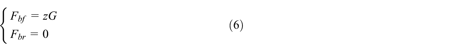
Based on the common adhesion coefficient of concrete and asphalt pavement 0.7, the intersection point C (6122, 467) between the f line and the ECE-R13 regulation line can be obtained, corresponding to a braking strength of 0.53. When the braking strength is
When the braking strength is
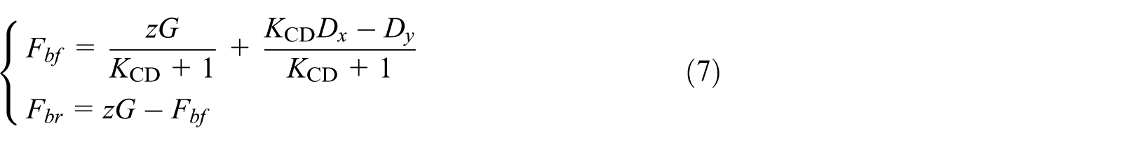
where
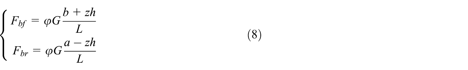
When the braking strength is greater than 0.7, it is an emergency braking. In order to ensure the safety of the braking, at this time, the braking forces of the front and rear axle should be provided by a more reliable friction braking as much as possible, and distributed according to the ideal braking force distribution I curve of the DE segment, for braking distance. Then the braking forces of the front and rear axle are distributed as follows
Regenerative braking force analysis of the motor
The motor has four-quadrant operating characteristics, which can be converted into generator operation during braking. The characteristic curve of the generator approximates the characteristic curve of the motor. It can be concluded that the calculation model of the regenerative braking force of the motor is as shown in equation (9)
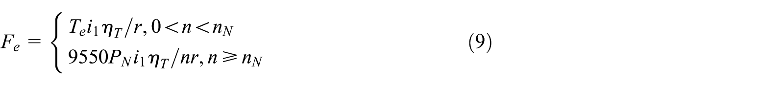
where
At the same time, in order to prevent the damage to the battery caused by excessive power generation, it is necessary to limit the output torque of the motor. The power generation can be calculated by equation (10) of the motor, the charging power of the battery can be obtained from equation (11), and the corrected torque of the motor can be obtained as equation (12)


where
Simulation model of control strategy
Modeling of braking force distribution model
The relevant parameters of the vehicle, motor, and battery are shown in Table 1.
Parameter table of the vehicle, motor and battery.

The braking performance required for different braking intents are different, and the braking forces assigned to the front and rear axles are also different. Based on automobile theory, 20 since the braking pressure is approximately linear with the brake pedal stroke, the brake pedal stroke percentage is taken as the braking strength in this article. According to equations (5)–(8), the braking force distribution model of the front and rear axle can be constructed in Simulink, which is shown in Figure 2.
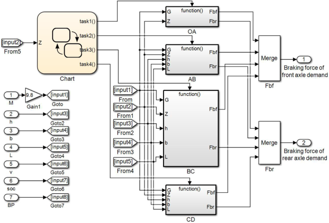
Braking force distribution model of the front and rear axle.
Modeling of regenerative braking force distribution of the motor
According to the above analysis, it can be seen that the working characteristics of the motor and the battery are the key factors affecting the recovery of the braking energy. 21 In addition, the braking strength, the SOC signal of the battery, the vehicle speed signal v, and the braking strength z are taken as inputs while using fuzzy control. The Mamdani type of controller is used, and the proportional coefficient Ke of the regenerative braking force of the motor to the front axle braking force are designed as the output signals, and the charging power characteristic of the battery is obtained to correct the output torque of the motor. Among them, the fuzzy subset of braking strength z is (low (L), medium (M), high (H)), the domain is [0, 1]; the fuzzy subset of vehicle speed v is (low (L), medium (M), high (H)), the domain is [0, 100]; the SOC fuzzy subset of the battery is (low (L), medium (M), high (H)), the domain is [0, 1]; the fuzzy subset of the regenerative braking proportional coefficient Ke is (very low (LL), low (L), medium (M), high (H), very high (HH)), the domain is [0, 1]; the membership functions of the braking strength z, the vehicle speed v, the battery SOC, and the regenerative braking proportional coefficient Ke are shown in Figure 3. The fuzzy control rules formulated are shown in Table 2, and the distribution model of the front axle braking force is shown in Figure 4).
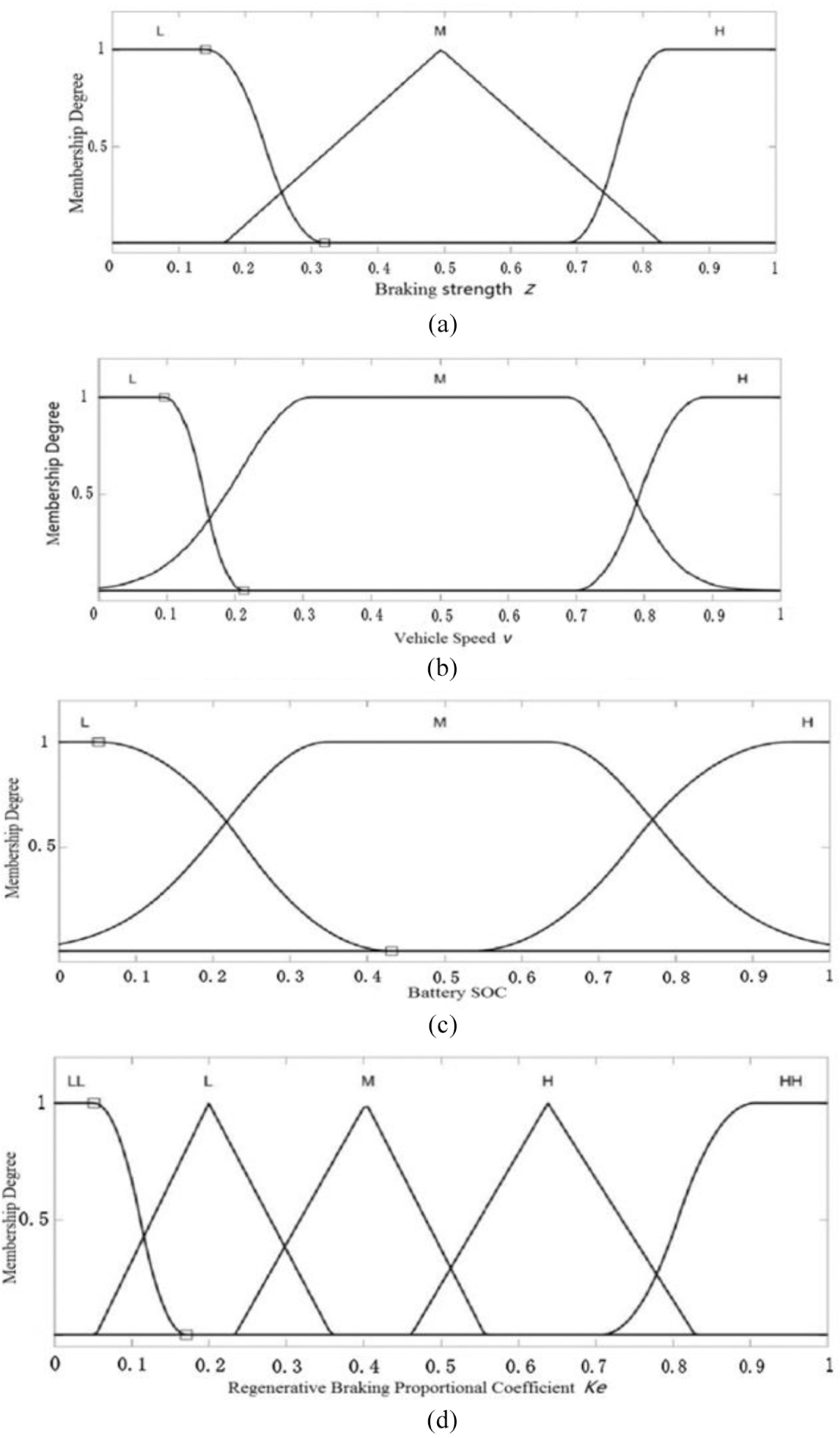
Membership function of input references: (a) membership function of the braking strength z; (b) membership function of the vehicle speed v; (c) membership function of the battery SOC; and (d) membership function of the regenerative braking proportional coefficient Ke.
Fuzzy rule table of the regenerative braking ratio Ke.

SOC: state of charge; LL: very low; L: low; M: medium; H: high; HH: very high.
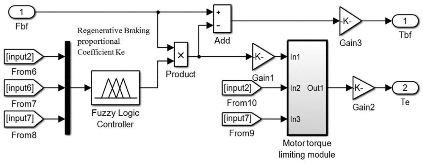
Braking force distribution model of the front axle.
Finally, the compilation tool is used to generate a “.dll” file of the entire Simulink model into the cruise simulation model.
Simulation results and analysis
According to the above strategy of braking force distribution, the road surface with an adhesion coefficient of 0.8 was selected for the simulation analysis of mild, moderate, and severe braking conditions in the co-simulation model.
Analysis of braking force of the front and rear axle under different braking strengths
Mild braking condition
The setting of mild braking condition is shown in Figure 5. The initial speed is 40 km/h, the braking time is 10 s and the initial SOC is 74.78%. The friction torques of the front and rear axle and the output torque of the motor during the braking process of the vehicle are recorded, and the braking force characteristics under mild braking conditions are shown in Figure 5.

Braking force characteristics under mild braking conditions.
It can be seen from Figure 5 that the braking strength of this working condition is less than 0.21. The braking force is all provided by the front axle, the friction braking and regenerative braking work together, and the rear axle does not participate in the braking process, it complies with the braking force distribution rules of segment AB.
Moderate braking condition
The setting of the moderate braking condition is shown in Figure 6. The initial speed is 60 km/h, the braking time is 4 s, and the initial SOC is 74.61%.

Braking force characteristics under moderate braking conditions.
It can be seen that the braking strength of this working condition is mostly between 0.21 and 0.53. The braking force is mainly borne by the front axle, and the proportion of the rear axle participation is relatively small. The braking force distribution of the front and rear axles is fitted to the BC section as shown in Figure 7. It is proved that the braking force distribution of this working condition is in accordance with the strategy formulated in this article. According to the fuzzy control rules of this article, the proportion of motor participation is larger.

Braking force distribution of front and rear axles of moderate braking.
Severe braking condition
The setting of the severe braking condition is as shown in Figure 8. The initial speed is 90 km/h, the braking time is 4 s, and the initial SOC is 73.89%.

Braking force characteristics under severe braking conditions.
It can be seen that when the braking strength is between 0.53 and 0.7, in the case of high-speed braking, in order to ensure the braking stability and the energy recovery, the friction braking is the main factor, and the proportion of the motor participation decreases, at the same time, due to the influence of battery charging power, the growth of motor torque slows down, and the braking force distribution of the front and rear axles is fitted to the CD segment as shown in Figure 9, which is in accordance with the braking force distribution rule constructed in this article.

Braking force distribution of front and rear axles of severe braking.
When the braking strength is greater than 0.7, it is emergency braking, according to the above braking force distribution rules, the motor hardly participates in braking and does not perform energy recovery. The energy recovery of the three braking strength conditions is shown in Table 3.
Energy recovery of three braking conditions.

SOC: state of charge; z: braking strength;
Battery SOC analysis under NEDC conditions
According to China’s standard for the certification of electric vehicle cruising range, GB/T 18386-2017 “Test Method for Energy Consumption Rate and Cruising Range of Electric Vehicles,” the braking energy recovery effect of this article is evaluated under NEDC conditions. The corresponding battery SOC curve with vehicle speed under different braking control strategies is shown in Figure 10.

SOC curve with vehicle speed v.
It can be seen from Figure 10 that under the condition of initial SOC of 75%, the variation of SOC of braking control strategy in this article is the least, which is reduced by 8.22%, but the SOC of braking strategy based on I curve reduces by 9.12%, and the SOC reduces by 10% without braking energy recovery. The purpose of braking energy recovery is to improve the energy utilization rate of the vehicle and extend the cruising range of the electric vehicle. Taking the using range of 95%–5% of battery SOC as calculation target, the cruising range of vehicle with braking control strategy of this article increases to 136.64 km. Compared with the braking strategy based on I curve, it increases by 10 km, and it increases by 22 km compared with the no braking energy recovery. It can be concluded that the braking control strategy of this article can effectively recover the braking energy.
Conclusion
A braking force distribution strategy of front and rear axle was proposed based on the I curve and ECE regulations of the braking characteristics of the vehicle. The distribution strategy of the regenerative braking force of the motor and friction braking force of the front axle was proposed and used the fuzzy control method, considering the working characteristics of the motor and battery.
A co-simulation model of the braking energy recovery control strategy of vehicle was proposed in Simulink and Cruise, according to the parameters of an electric vehicle model, and the control strategy proposed in this article was simulated under various braking conditions and NEDC conditions.
The results showed that the friction braking force of front and rear axle and the regenerative braking force of the motor were in accordance with the braking force distribution principle formulated in the article. The braking energy recovery rates under the three braking conditions were 27.39%, 43.43%, and 42.41%, respectively. Taking the using range of 95%–5% of battery SOC as calculation target, the cruising range of vehicle with braking control strategy of this article increases to 136.64 km. The braking energy recovery effect is valid, which could effectively improve the battery SOC and extend the cruising range.
Footnotes
Declaration of conflicting interests
The author(s) declared no potential conflicts of interest with respect to the research, authorship, and/or publication of this article.
Funding
The author(s) disclosed receipt of the following financial support for the research, authorship, and/or publication of this article: This research was supported under National Nature Science Foundation of China (51205055), Science and Technology Major Project in Heilongjiang Province (E2016003), and the Fundamental Research Funds for the Central Universities (2572019BG01).