
Abstract
A new type of built-in composite electromagnetic and frictional braking structural scheme and its corresponding coordinated control strategy were proposed to enhance the braking effects for the electric vehicle. Fuzzy control theory was applied to design the coordinated control strategy for the electromagnetic and frictional braking system. In comparison to lower braking strength and moderate braking strength, the slip ratio of high braking strength was maintained at near 0.15. It effectively avoided the wheel getting locked and provided relatively large braking torque in the process of braking. The integrated system using a fuzzy control strategy can effectively shorten the braking time, enhance the braking safety in the braking process.
Introduction
With improvements in the performance of driving motors in electric vehicles,1–3 attention has been paid by experts and researchers to the technology of the hub-wheel motor.4,5 The electric vehicle directly driven by hub-wheel motors not only simplifies the automotive chassis, but also improves the efficiency of the powertrain.6,7 In order to analyse the influence factors of the braking torque of the permanent magnet retarder, a permanent magnet retarder with a gradable braking torque is designed by Hen et al. 8 In addition, the phase plane method was used to determine the stability control state.9,10 A voltage variable charging structure for an in-wheel motor was designed based on the battery management system (BMS) for improving the regenerative braking energy recovery efficiency by Wang and Hen 11 A drive torque distribution algorithm was proposed to improve the drive efficiency of the vehicle system by Chen et al. 12 Further, Zhao et al. 13 explore the energy transfer and distribution strategy of a hybrid energy storage system with a battery and ultracapacitor to increase the recovery and utilization efficiency of regenerative braking energy. The strategy considers the charge-discharge loss of the ultracapacitor and battery as well as DC/DC converter loss. However, for its braking system, it relied on installed disc braking because of the restrictions of the wheel size. For the most part, when the vehicle needs a long time to brake, the braking pads will be dissipated and will heat which reduces braking performance, and even causes braking failure.
An electromagnetic braking is a non-contact braking which takes advantages of smooth braking, no friction, no dust and other elements. In the past several decades, there have been important research achievements in these areas. Cunha et al. 14 presented the design stages, development and testing of an electromagnetic braking by the action of induced currents mainly aiming to use as a variable load in three phase induction motors tests. Fujimoto and Harada 15 studied a braking force distribution model that considers the acceleration and speed of the vehicle to optimize the distribution of braking force. Senkal and Gurocak 16 proposed fully controllable, multi DOF magnetic braking that utilize the change in shear viscosity of either electrorheological (ER) fluid, Bae and Kim 17 presented the use of an electric braking to reduce speed at the end of the stroke, and proposed a circuit breaker which adopts an electric braking that has a variable speed reduction function such that the continued rebound phenomenon ceases to occur. Iqbal and Yi 18 designed a new, bilayer multipole electromagnetic braking which provides high fidelity of free motion through an absolutely disconnected rotor. Zhao et al. 19 presented a novel electric-hydraulic hybrid steering system with multiple steering modes to reduce energy consumption while steering and improving the handling stability of electric vehicles.
This paper is organized as follows: First, it describes the development of a preliminary structure of a new electric wheel, including an external rotor motor, hub, electromagnetic braking, friction braking and the return spring. Second, mathematical models based on the proposed integrated braking system structure of friction braking, electromagnetic braking and frictional-electromagnetic braking are established. Third, the vehicle dynamic model of 7 DOF was established, and the braking performances of the built-in composite structural scheme for the frictional and electromagnetic braking results are presented. Fourth, the theory of fuzzy control is applied to design the coordinated control scheme. Finally, the simulation results show that the integrated system using a fuzzy control strategy can effectively avoid the wheel getting locked and provide relatively large braking torque in the braking process.
Structure of the new electric wheel
In giving consideration to the characteristics of the electromagnetic braking and the hydraulic braking, as well as to the structure and dimensions of the electric wheel, we provide a new type of an integrated structure frictional braking and electromagnetic braking, which is shown in Figure 1. The electromagnetic braking and the hydraulic braking integrated together not only ensure the fulfilment of the requirements of the material but also make the heat which is produced by the electromagnetic braking and the frictional braking dissipates. Thus, to a large extent, they efficiently avoid the hot recession of the braking system.

The new structure of the hub-motor. (i) External rotor motor, (ii) hub, (iii) electromagnetic braking and (iv) friction braking.
The structural features of the new electric wheel are as follows: a new type of the integrated structure frictional braking and electromagnetic braking based on the electric wheel which was shown in Figure 2. It includes a hub-wheel motor driving system which adopts a three-phase permanent magnet synchronous motor, cooling system, frictional braking system and electromagnetic braking system. The motor has the structure of an outer rotor and an inner stator. A cooling duct was opened in the stator which is connected with the external cooling system. The working principle of the structure of the new electric wheel is as follows:
When the electric wheel requires only a frictional braking, the controller opens the first electromagnetic hydraulic valve. The high-pressure oil goes into the hydraulic cylinder which was formed by the exterior wall of the cylinder and the internal wall of the cylinder. The piston is pushed by the high-pressure oil to overcome the pre-tightening force of the return springs. Meanwhile, the piston moves towards the composite braking bracket. Frictional torque is produced when the frictional plate is in contact with the frictional braking surface of the composite braking bracket which blocks the rotation of the composite braking bracket and prevents the rotation of the axle and the wheel hub. Ultimately, this stops the vehicle.
When the electric wheel requires only the eddy current braking, the electric current is provided into the electromagnetic braking coil by the controller. A magnetic field is produced around the electromagnetic braking coil. When the magnetic induction line is cut by the copper clad layer, an eddy current is produced around the copper clad layer which produces eddy current braking torque under the effect of the magnetic induction line. The eddy current braking torque blocks the rotation of the composite braking bracket and prevents the rotation of the axle. Ultimately, this stops the vehicle.
When the electric wheel requires integrated frictional braking and electromagnetic braking, the controller opens the first electromagnetic hydraulic valve and current is provided into the electromagnetic braking coil. Ultimately, this can activate the frictional braking and electromagnetic braking simultaneously.

The integrated structure of the frictional and electromagnetic braking based on the hub-motor: (i) hub-wheel motor, (ii) return spring, (iii) piston, (iv) composite braking bracket, (v) electromagnetic braking bracket, (vi) electromagnetic braking coil, (vii) locating port, (viii) diversion port, (ix) first electronic control hydraulic valve, (x) friction plate and (xi) guide rod.
To improve the heat dissipation capacity of the integrated structure of the frictional and electromagnetic braking, a heat diversion port (Figure 2: (viii) diversion port) was designed in the middle of the composite braking bracket. This heat diversion port produces friction and an eddy current concentrates the heat dissipation in the middle of the composite braking bracket. The left and right sides generate heat separately during friction-electromagnetic composite braking, which is beneficial to the integrated structure of the frictional and the electromagnetic braking and improves the heat dissipation of the braking disc.
The differences between this new type of electric wheel and existing electric wheels are that the braking system contains integrated system frictional and electromagnetic brakings. Its characteristics are as follows:
First, the frictional braking and the electromagnetic braking share a composite braking bracket. Its inner surface, which is close to the side of the electromagnetic coil, produces electromagnetic torque and its outer surface produces frictional torque.
Second, a bearing is used to connect the electromagnetic braking bracket and the axle. A positioning boss is set between the composite braking bracket and the electromagnetic braking bracket, which ensures the gap between the electromagnetic braking coil and the copper clad layer, as well as being able to ensure that the electromagnetic braking coil produces a firmly stable magnetic field.
Third, the frictional braking is produced by the exterior surface of the composite braking bracket and the electromagnetic braking is produced by the interior. Although the frictional braking wears, which will lead to the exterior composite braking bracket become thinner, this does not affect the internal electromagnetic braking.
Finally, the design of the heat diversion mouth in the middle of the composite braking bracket can allow the heat to be separately produced which greatly improves the radiation effect of the braking disc.
The vehicle dynamics model and integrated braking system model
Vehicle dynamic model of 7 DOF
In order to study the braking conditions of the vehicle, a vehicle dynamic model of 7 DOF was established. Figure 3 shows the 7 DOF vehicle model, which includes longitudinal, lateral and yaw motion and the rotation of four wheels. It ignores the motion of pitch, roll and vertical motion, which have less impact on the vehicle’s braking stability. The vehicle loads are as follows. 20
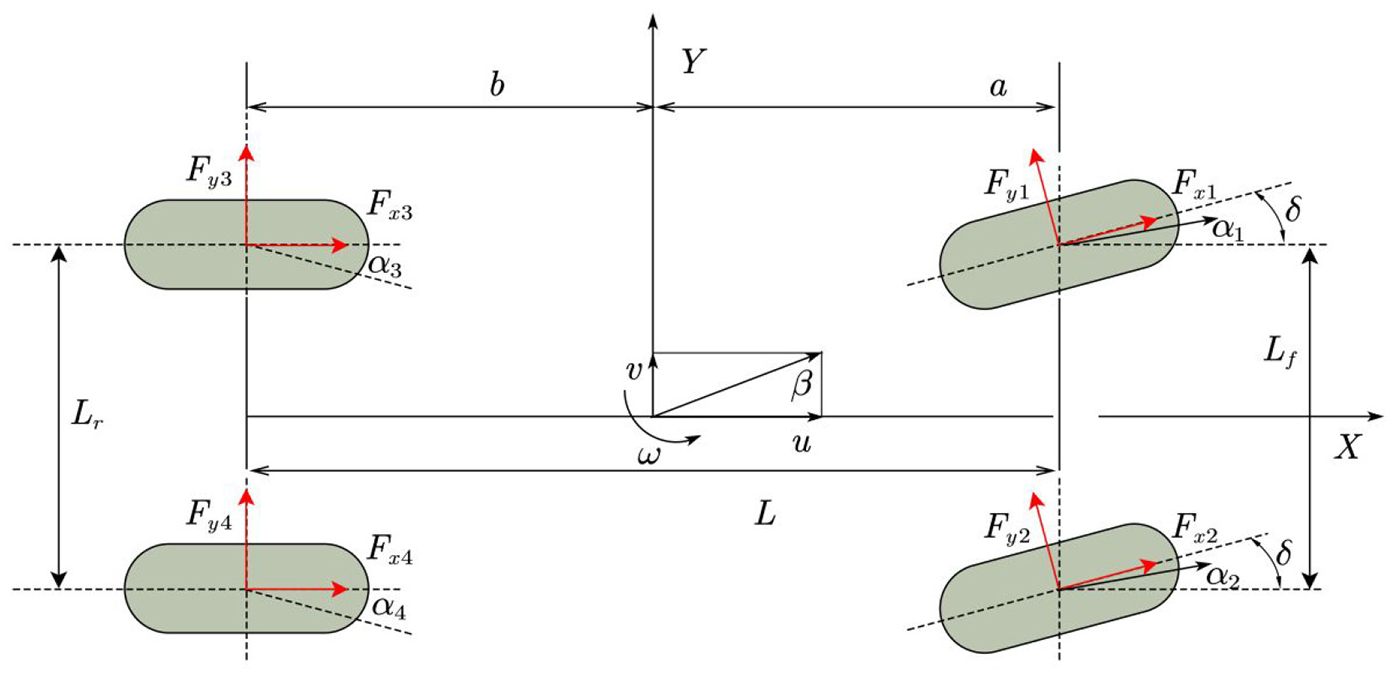
The 7 DOF vehicle dynamics model.
The longitudinal force equation of motion of the vehicle can be expressed as:

The lateral force equation of motion of the vehicle can be expressed as:

The yaw moment equation of motion of the vehicle can be expressed as:

The balance equation of the wheel torque can be expressed as:

Wherein,
This paper uses the ‘magic formula model’ as the tire model. The ‘magic formula’ of Pacejka is a tire mechanical model which is widely used in vehicle handling dynamics. The model can represent the relationship between the adhesion coefficient and the longitudinal slip rate of the wheel, as well as the relationship between the longitudinal forces of the tire and slip rate. Details can be found in references.21–23
Mathematical model of integrated braking system
When conducting theoretical analysis and simulation experiments on the braking performance of the new electric wheel, it is necessary to establish a simplified mathematical model according to the dynamic characteristics of the vehicle and the design scheme of the composite braking system. Much research at home and abroad has been carried out concerning the separate hydraulic braking system and regarding the electromagnetic braking system model. In this paper, we analyse the modelling methods of the hydraulic braking, the electromagnetic braking and the integrated electromagnetic and frictional braking.
Mathematical model of the hydraulic braking
Due to the complexity of the Electronic Hydraulic Braking (EHB) system, with the goal of satisfying simulation accuracy, the complex hydraulic system is simplified into a simple system which is comprised of some basic hydraulic components and ignores pressure loss while describing the relationship between pressure and flow. 24 The electromagnetic-hydraulic composite braking system designed in this paper uses a composite braking disc, and its hydraulic braking function is the same as that of a traditional disc braking. When the car is running, the braking disc rotates with the wheels. When the braking wheel cylinder generates pressure, the wheel cylinder piston pushes the friction plate to compress the braking disc to generate contact friction, thereby generating frictional braking torque. The composite braking disc is affected by the force configuration shown in Figure 4.

Force analysis of hybrid braking plate.
Under normal circumstances, the mechanical relationship between the pressure applied by the braking wheel cylinder piston to the friction plate and the wheel cylinder pressure are expressed as follows:25,26

Wherein,
Therefore, the pressure of the composite braking disc can be expressed as 27 :

Wherein,
If we take a small unit area on the composite braking disc, the friction force it receives is

Bringing the above formula into the below formula gives the hydraulic braking torque:

If the equivalent radius is applied:

The hydraulic braking torque can be expressed as:

Mathematical model of the electromagnetic braking
When electromagnetic braking functions, it is related to the structural parameters of the braking and the speed and temperature of the rotor disc. There will be complex magnetic and electric fields around the braking during operation. Thus, many researchers adopt this method that assumptions and ignoring some influencing factors braking system are related to its structural parameters when researching this aspect.28–30 Figure 5 shows the dimension parameters of the electromagnetic system in the integrated braking system. The eddy current braking torque can be expressed as:

Wherein,

Wherein,

Where


Wherein,
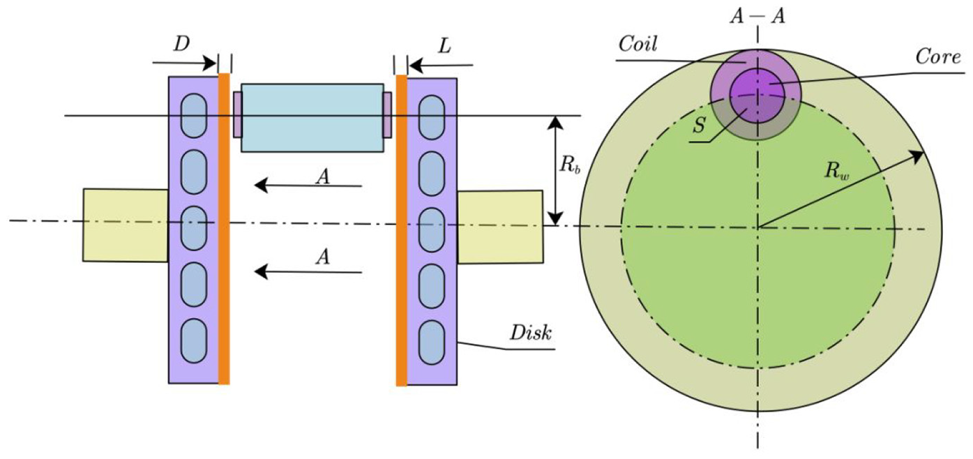
Electromagnetic system parameters in integrated braking system.
Mathematical model of the integrated electromagnetic and frictional braking
The mathematical model of the integrated electromagnetic and frictional braking can be expressed as follows:

The dynamics vehicle model carried out in this paper mainly includes the body module, the tire module, the wheel module and the intermediate calculation module. The input is mainly taken from the braking strength, the steering angel of the front wheels and the initial braking speed. The vehicle dynamics model is shown in Figure 6.

The dynamics vehicle model.
Control strategy
The strategy of braking force distribution
The coordinated control strategy of electromagnetic and frictional braking force in Figure 15(b) of this paper is described as follows: when the driver’s braking intensity
Fuzzy control strategy
Aiming at analysing the braking configuration with which the integrated system electromagnetic and frictional braking affected the automobile, the theory of fuzzy control was applied in the modelling and simulation of this system.
It is universally acknowledged that the fuzzy control system can realize optimal control of the target system by controlling the slip rate. The fuzzy system has three variables which include deviation (E), deviation change rate (Ec) and the control variable (Du).
The control variable of the fuzzy controlling system is the slip rate, whose input is the feedback value of the actual slip rate (s1). If the optimal slip rate is set as s, the deviation is e = s − s1 and the deviation change rate is e1. The output of the fuzzy system is the coil current (I) of the electromagnetic braking. Accordingly, the deviation corresponds to the fuzzy language variables. The deviation change rate (e1) corresponds to Ec. The output of the fuzzy system corresponds to controlled variable Du.31,32
The structure diagram of the fuzzy control system of the integrated electromagnetic braking and friction braking system is shown in Figure 7.
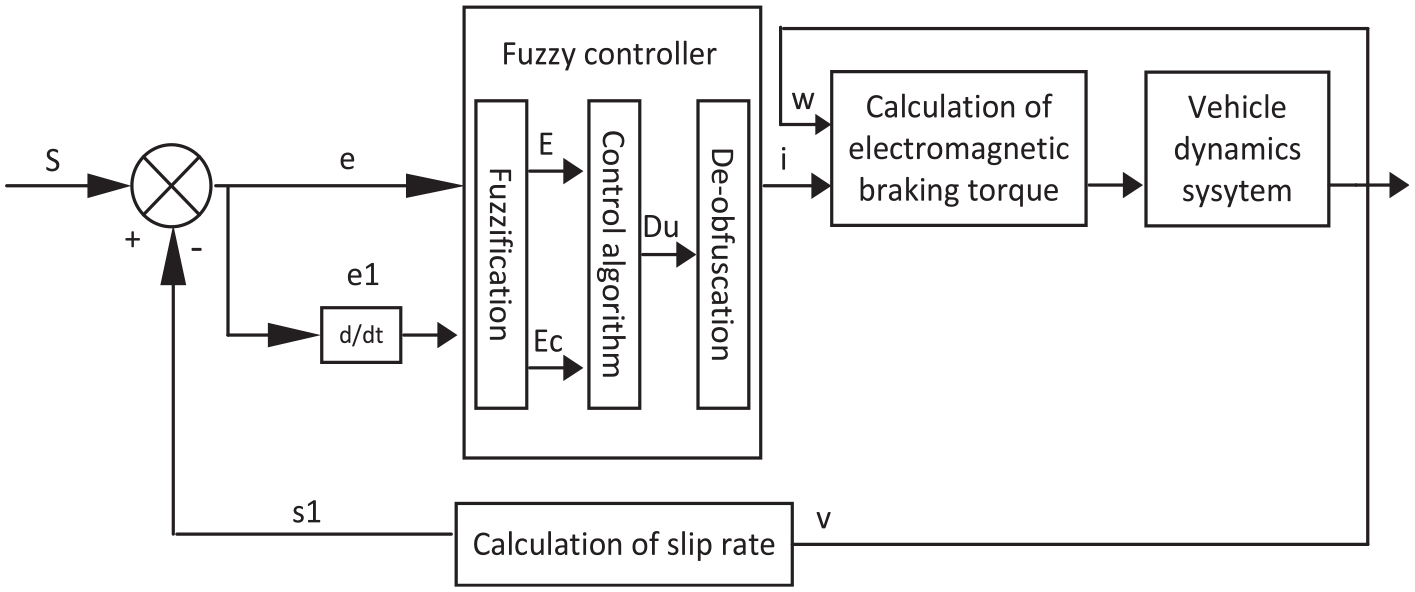
The integrated electromagnetic braking and friction braking system.
The optimal slip rate is set as s. The fuzzy domain of the linguistic variables (E) and (Ec) in the fuzzy controller is [−6, 6]. The fuzzy domain of the output of the fuzzy language variables (Du) is [0, 20]. In order to achieve more accurate control over the slip rate, the linguistic values of the fuzzy language E are set as {NB, NM, NS, NW, Z, PW, PS, PM, PB}, the linguistic values of the fuzzy language Ec are set as {NB, NM, NS, Z, PS, PM, PB}, the linguistic values of the fuzzy language Du are set as {NB, NM, NS, NW, Z, PW, PS, PM, PB}. The fuzzy control rules are formulated based on the following:
If deviation (E) is Negative Big (NB), the slip rate (Ec) is also Negative Big (NB), indicating that the actual slip rate is very large, and that the trend of slip change rate is also very large. Thus, it should greatly reduce the current of the electromagnetic braking coil I, namely, the amount of I is Negative Big (NB). If deviation (E) is Positive Big (PB), indicating that the actual slip rate is far from the optimum, and at the same time, if the slip change rate is also Positive Big (PB), this means that the slip rate is far from the best slip rate. Therefore, the current of the electromagnetic braking coil should be greatly increased – output (Du) is Positive Big (PB). If deviation (E) is NW, and the slip rate is PS, indicating that the actual slip rate is slightly larger than the optimal slip ratio, it is close to the optimal slip ratio with low velocity, at the same time, it should keep the current of the electromagnetic braking coil, and so the output (Du) is Z. Fuzzy control rules are shown in Table 1, and the membership function of input and output variables of the fuzzy controller are shown in Figures 8 to 10. Figure 11 is the curve of the input and output diagram.
Fuzzy control rule.


Slip rate deviation membership function.

Slip rate change rate membership function.

Control variable membership function.
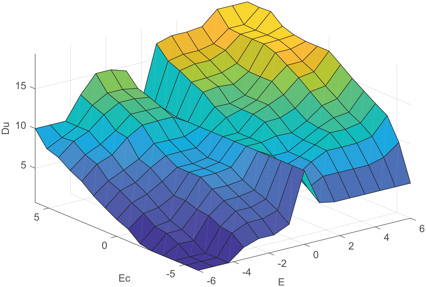
The curve of the input and output diagram.
The established fuzzy control system was simulated and analysed through MATLAB/Simulink, then the obtained fuzzy control rule table was placed in the controller to realize real-time monitoring and control. The system simulation model is shown in Figure 12. In Figure 12, the In1 port was the wheel angular velocity required to calculate the braking torque generated by the friction braking, and the In2 input ports of the vehicle dynamics system was the calculated electromagnetic braking.
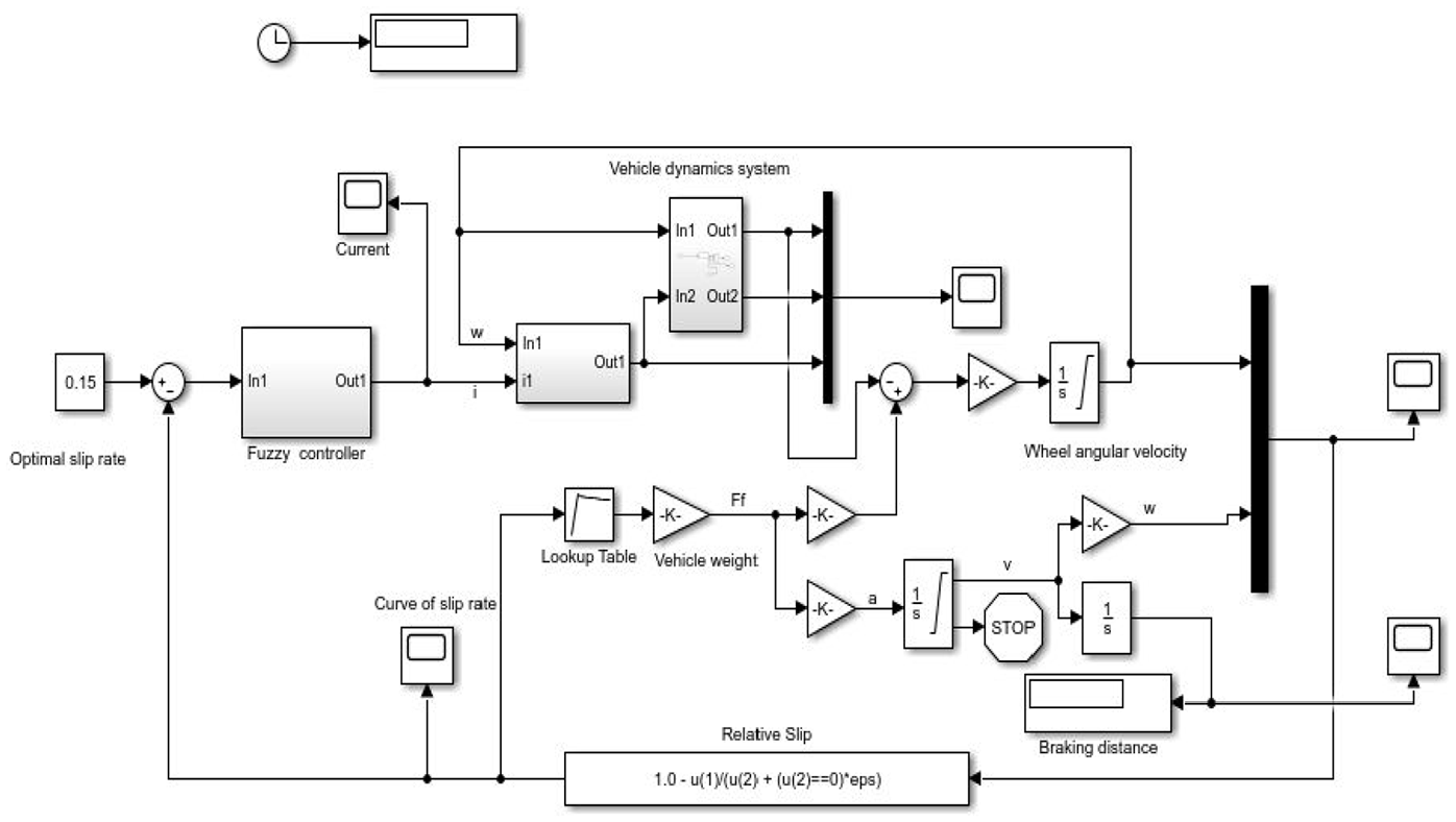
The fuzzy control simulation model of the integrated system.
Simulation and analysis
The initial conditions for simulation: the automobile mass is 970
Simulation and analysis of vehicle dynamic model
When only the frictional braking is applied on the vehicle, the intensity of the hydraulic braking force added to the wheel cylinder setting is as follows: the simulation stops when the speed is zero; the initial speed is 30

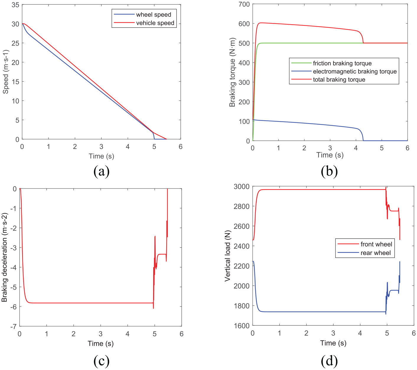
The simulation results of the frictional braking: (a) the curve of speed, (b) the curve of braking torque, (c) the curve of braking deceleration and (d) the curve of vertical load.
Figure 13(a) shows that the speed of the vehicle is reduced to zero in 6 s with the addition of frictional braking torque. Figure 13(b) to (d) are respectively for the curve of braking deceleration, the curve of braking force and the curve of the vertical load. The largest braking deceleration can be reached at about 5
When only the electromagnetic braking is applied to the vehicle, the electromagnetic braking torque will be decreased with the decreasing of the vehicle speed. Especially at the end of the braking the electromagnetic braking torque will rapidly decline and the speed will decrease slowly. As a result, the setting is as follows: the simulation time is 15

The simulation results of the electromagnetic braking: (a) the curve of speed, (b) the curve of braking torque, (c) the curve of braking deceleration and (d) the curve of vertical load.
From the above figures, it can be seen that when the current is fixed, the decreasing trend of the electromagnetic braking torque becomes obvious with a decrease in speed. As a result, the strength of braking deceleration shrinks and there is decreasing trend of speed. These are well represented in Figure 14(a) to (c). From Figure 14(b), it can be concluded that the electromagnetic braking can provide a braking strength of about 0.1−0.13. As is well known, the front and rear of the vehicle load will be transferred in braking, in particular, the front load will be increased and the rear load will be reduced, which is shown in Figure 14(d).
When both the frictional braking and electromagnetic braking are applied to the vehicle, the above two kinds of cases combined together, the setting is as follows: the initial speed is 30
The simulation results of the integrated braking: (a) the curve of speed, (b) the curve of braking torque, (c) the curve of braking deceleration and (d) the curve of vertical load.
When the electromagnetic braking torque is withdrawn, it will cause slight fluctuations in the slip rate, and will cause the total braking torque to drop suddenly, which will cause the vehicle’s braking distance and braking time to extend. This affects driving safety.
From the figures, it can be seen that when we add the electromagnetic braking to the frictional braking, the total braking torque increased, the braking strength increased and the braking time shortened. However, due to the electromagnetic braking torque, which changes along with the speed, in the whole process the total braking torque and the braking deceleration strength see a certain reduction.
In addition, from a comparison of the three kinds of vertical load curves, it can be clearly found that with the increasing of braking strength, the gap of the vertical loads on the front and rear axles are also extended, which is in line with the actual braking situation.
Simulation and analysis of fuzzy control
The fuzzy control system was simulated in MATLAB/Simulink, which is shown in Figure 12. The two inputs of the fuzzy controller are used to calculate the speed of the wheel and the current of the electromagnetic braking coil which are needed to calculate the electromagnetic braking torque. The output is the electromagnetic braking torque.
In order to analyse the performance of the integrated braking system, different types of braking strength (z) had been made to validate the integrated system. Figure 16 shows the results of lower braking strength (z = 0.15), moderate braking strength (z = 0.5) and high braking strength (z = 0.7).
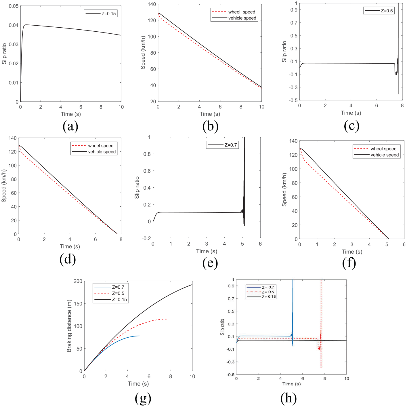
Results of braking performance for three braking strengths: (a) slip ratio of lower braking strength, (b) velocity of lower braking strength, (c) slip ratio of moderate braking strength, (d) velocity of moderate braking strength, (e) slip ratio of high braking strength, (f) velocity of high braking strength, (g) braking distance for three strengths and (h) slip ratios for three braking strengths.
Figure 16(a) shows that, when braking starts, the slip ratio of lower braking strength is very low. The slip ratio is maintained at or near to 0.04. When the wheel speed decreases, the braking torque of lower braking strength is reduced as well. Hence, the vehicle speed and wheel speed approach each other in Figure 16(b), and the curve is smoother than that of Figure 16(d). There is little abnormal fluctuation in the slip ratio curve of Figure 16(c) and (e), which caused by electromagnetic braking force withdrawal. Figure 16(d) and (f) show the difference between vehicle speed and wheel speed – it is rather large. Figure 16(a), (c) and (e) show the slip ratio curve of the integrated system. Their curve is very smooth, the value is stable at a certain value and the fuzzy control is effective. But the slip ratio of lower braking strength and moderate braking strength cannot reach 0.15. The slip ratio of high braking strength can stabilize at 0.15.
Figure 16(e) shows a rapid response to braking action, almost immediate. Due to possible optimal slip ratio effect, the wheel speed has an obvious variation. The braking effect is obvious and the whole braking time only needs about 5 s.
Figure 16(g) shows the braking distance for three kinds of braking strength. As the braking strength increases, the braking distance is significantly shortened and the braking time is also reduced. High braking strength has a more rapid response than other braking strengths, and its braking time reaches about 5 s. Figure 16(h) shows the slip ratio for three braking strengths in the process of braking. The slip ratio of high braking strength is maintained at near 0.15. It effectively avoids the wheel getting locked and provides relatively large braking torque when braking.
Conclusion
In this paper, we discussed the braking performance analysis of an integrated system. First, we designed a new type of built-in composite structural scheme electromagnetic and frictional braking system. Based on the structure of the integrated system, a mathematical model and a simulation model were built to calculate the braking performance. Second, a fuzzy controller based on MATLAB/Simulink was designed which was constructed to validate and analyse the performance of the integrated system. Throughout many simulations on lower braking strength, moderate braking strength and high braking strength – the results indicated in Figure 16– the conclusions reached are as follows:
Because the current electric wheel adopts a single frictional braking which causes excessive wear, overheating and thermal recession, a new type of integrated structure was put forward. The structure can effectively realize an integrated system frictional and electromagnetic braking in the electric wheel.
Mathematical models based on the proposed integrated braking system structure of friction braking, electromagnetic braking and frictional-electromagnetic braking were established. A vehicle dynamic model of 7 DOF was established, and the braking performances on the basis of the integrated frictional and electromagnetic braking system are presented.
Through simulation analysis, it can be concluded that when considering the slip ratio curve of the integrated system, the curve is very smooth, the value is stable at a certain value and the fuzzy control is very effective.
In comparison to lower braking strength and moderate braking strength, the slip ratio of high braking strength was maintained at near 0.15. It effectively avoided the wheel getting locked and provided relatively large braking torque in the process of braking.
This study is aimed only for the structure design and coordinated control. However, heat dissipation is a key issue to solve for electromagnetic and frictional braking systems. In further research, the corresponding heat dissipation research about the proposed new electric wheel structure is also a key area to explore. Moreover, the effectiveness of the proposed coordinated control will be validated by the hardware in loop testing.
Footnotes
Declaration of conflicting interests
The author declared no potential conflicts of interest with respect to the research, authorship and/or publication of this article.
Funding
The author disclosed receipt of the following financial support for the research, authorship and/or publication of this article: This work was supported by the Science and technology research project of Jiangxi Provincial Department of education in 2019 (Grant No GJJ191282) and ‘13th Five-Year Plan’ key project of Jiangxi Province Educational Science in 2018(Grant No 18ZD091)