



Abstract
The modal characteristics of the multi-rotor coupling system in an integrally geared compressor (IGC) for Compressed Air Energy Storage (CAES) have a critical influence on system dynamics and reliability under variable operating conditions. Taking into account the coupling effects of multi-gear meshing, a mathematical model of the IGC rotor system was established. Firstly, the modal characteristics of each independent shaft train were calculated before and after the gear meshing. Analysis revealed that gear engagement alters the natural frequencies and mode shapes of individual shaft trains and introduces new gear-related frequency components. Subsequently, an orthogonal experiment was designed for the control parameters (power, rotational speed, inlet oil temperature), followed by range analysis and analysis of variance (ANOVA). This process revealed the effects of each control parameter on the various modal characteristics and the derived natural frequencies of the rotor system. Rotational speed exhibited the highest sensitivity, followed by power and then inlet oil temperature. Multivariate linear regression prediction models were then established for each dependent variable, yielding the regression coefficient values for each control parameter. Finally, validation using field vibration data confirmed the accuracy of the method and models, providing a theoretical basis for optimizing CAES control strategies.
Keywords
Introduction
With the continuous increase in the proportion of renewable energy installed capacity worldwide, wind and photovoltaic (PV) power generation are gradually becoming the mainstay of new power systems. This trend, however, brings numerous new challenges to power systems, including power balance, energy accommodation, and grid security and stability control.1,2 To address the inherent randomness, volatility, and intermittency of renewable power generation, energy storage technology has emerged as a crucial supporting technology for building new-type power systems and enhancing power ancillary service capabilities.
CAES is an emerging long-duration, large-scale energy storage technology. It offers significant advantages such as large storage capacity, short construction period, long operational lifespan, and environmental compatibility, and has been developing rapidly in major electricity-consuming countries in recent years. CAES holds broad application prospects in areas including peak shaving and valley filling, peak regulation, renewable energy accommodation, and ancillary services. It is of great importance for promoting the development of new-type power systems in the context of “Carbon Peak and Carbon Neutrality”.3–5
CAES technology is based on a modified gas-turbine cycle in which compression and expansion are separate processes. In the charging phase, excess electricity is used to compress air, which is then stored; the heat of compression is concurrently stored in a Thermal Energy Storage (TES) system. In the discharging phase, the stored air is released and heated before being expanded through a turbine to generate electricity.6,7 The two commercial CAES facilities—the Huntorf plant in Germany (commissioned in 1969) and the McIntosh plant in the United States (commissioned in 1991)—employ underground storage with capacities of 532,000 m3 and 270,000 m3, respectively. The potential of CAES to compensate for fluctuations in renewable energy was first mentioned as early as 1976 and again in 1981, although it did not receive significant attention at the time. However, this situation has changed dramatically with the widespread integration of intermittent renewable energy sources, such as wind and solar PV, into power supply systems across many countries.8–10 In recent years, CAES research has primarily focused on thermodynamic cycles, design and analysis of key components, and system integration and validation. The main components of a CAES system include the motor, compressor, heat exchanger, storage vessel, expander, and generator.11–13
The turbocompressor is one of the core components in a CAES system, and its performance directly determines the overall efficiency and economy of the system. The pressure ratio required in a CAES system is typically as high as 40–80 or above, making multistage compression a common configuration. Multistage centrifugal compressors are mainly divided into single-shaft and multi-shaft types. Among these, the multi-shaft geared centrifugal compressor offers advantages such as high efficiency, compact structure, and ease of inter-stage heat recovery, making it more suitable for large-scale CAES systems. 14 Efficient energy conversion is central to energy storage technology. Therefore, enhancing the operational stability of the compressor under variable working conditions is one of the key technical challenges for CAES systems.
In terms of key technologies for IGCs, scholars have conducted multidimensional research. Wang et al. 15 considered the gear tooth surface friction effect, calculated tooth profile deformation caused by contact temperature variation, and investigated the influence patterns of rotational speed, torque load, and lubricant viscosity on system response. Li et al. 16 proposed a control strategy for the grid-connection process of an Advanced Adiabatic Compressed Air Energy Storage (AA-CAES) system, achieving efficient and stable operation of the energy storage system by regulating parameters such as the power and speed of the turbocompressor and expander. Song et al. 17 investigated the mechanical and electrical run-out errors at key journal locations of the IGC rotor. They demonstrated that a combined approach involving demagnetization, cold extrusion, and micro-peening can effectively reduce mechanical-electrical run-out errors. To mitigate inducer stall and extend the low-flow operating range, Pelton et al. 18 proposed an open impeller design with a passive recirculation casing treatment for wide-range centrifugal compressor stages in supercritical CO2 (sCO2) power cycles. Modekurti et al. 19 proposed an integrated model for post-combustion CO2 compression using an integrally geared multistage centrifugal compressor. Using dimensionless performance curves, they simulated its off-design performance and analyzed the response of key variables to disturbances. Zhang et al. 20 developed a dynamic model of a gear-rotor-bearing system, including bearing dynamics, axial force, and torque. They analyzed the dynamic response using a five-shaft transmission system as a case study. Yang et al. 21 introduced a general method for calculating the maximum shaft radius in the unbalanced response orbit of geared rotor systems, providing mathematical proof and comparing it with classical modal synthesis. Zhang et al. 22 established a finite element model of a centrifugal compressor rotor using a 6-DOF rotating beam element. They investigated how changes in bearing stiffness under load affect critical speeds and resonance. Wang et al. 23 studied the effect of CAES variable conditions on a three-gear rotor system. Their finite element model, incorporating unbalance and torque excitation, was validated experimentally. Yang et al. 24 investigated the internal loss mechanisms in a supercritical CO2 centrifugal compressor, comparing the effects of three working fluids—sCO2, ideal CO2 (ICO2), and ideal air—on compressor performance and loss distribution. Lin et al. 25 conducted a numerical study on the full mainstream channel coupled with the impeller backside cavity (IBC) in a centrifugal compressor for CAES. They analyzed the internal flow field within the IBC and the compressor coupling characteristics under variable operating conditions. Wang et al. 26 proposed a self-recirculation casing treatment implemented at the diffuser to extend the stability margin. This method defines the recirculation angle and establishes physical parameters to characterize improvements in stall margin (ηstall) and stable flow range, effectively mitigating compressor stall.
As indicated by the above literature, research on IGCs has primarily focused on the internal flow characteristics under single operating conditions or the dynamic response of individual gears, whereas few studies have addressed the modal characteristics of the coupled multi-rotor system. Regarding the parameters incorporated into mathematical models, the effects of mesh stiffness and damping of multiple gear pairs are rarely considered. Variable operating conditions are a typical feature of multi-shaft IGCs used in CAES systems. As the external load and rotational speed continuously vary, the meshing states of the gear pairs, as well as the stiffness and damping parameters of the bearings, undergo changes, leading to dynamic variations in the modal characteristics of the entire rotor system.
Due to the multi-shaft configuration of IGCs, where individual rotors often operate above their first or second critical speeds and multiple gear meshing zones are present, their dynamic behavior and modal characteristics are exceptionally complex. Consequently, it is essential to study the rotor system, which comprises impellers, gears, shafts, and bearings, as an integrated whole. This necessity is even more pronounced in the context of CAES applications under variable operating conditions, where the modal characteristics and their variation patterns in IGC rotor systems become particularly intricate and volatile, posing significant constraints on the unit’s operational stability and reliability.
Mathematical model
Multi-shaft rotor system configuration
The process flow of the CAES system is shown in Figure 1, in which the core device is the multi-shaft integrally geared compressor (IGC). The configuration of its rotor system is illustrated in Figure 2. It consists of a bull gear component (BGC), a first- and second-stage high-speed shaft component (H1), a third-stage high-speed shaft component (H2), and a fourth- and fifth-stage high-speed shaft component (H3). The bull gear simultaneously drives the three high-speed shafts, which in turn rotate the corresponding impeller stages to achieve multistage compression of air, thereby delivering the optimum flow rate and pressure required for energy storage. Flow diagram of the CAES system. Layout of the three high-speed shaft five-stage compression rotor system.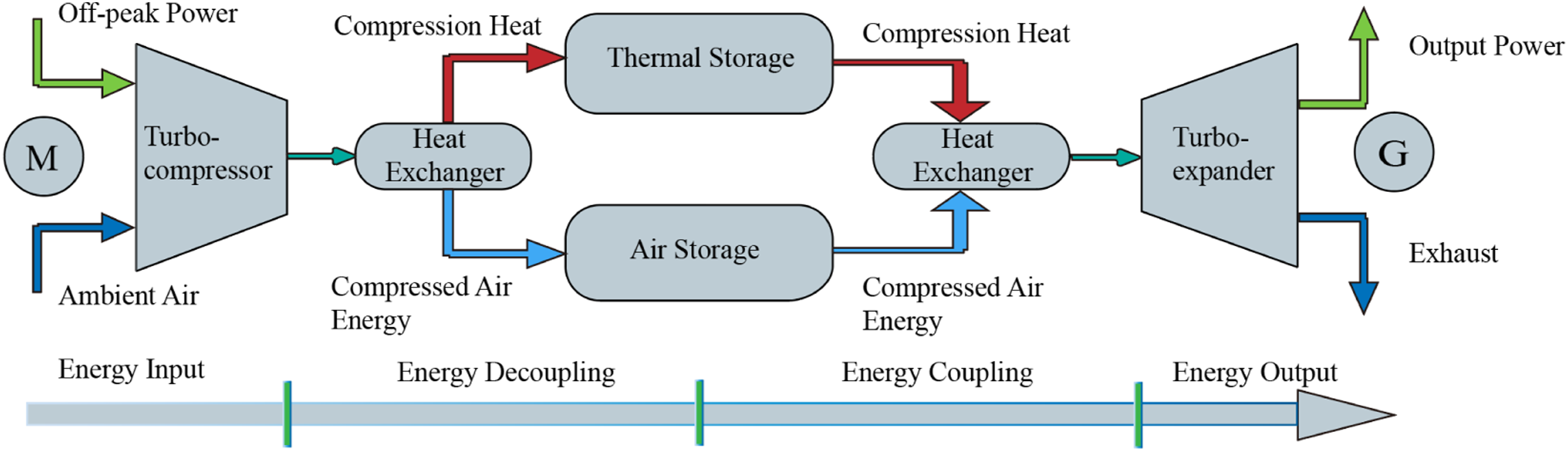

Equations of motion
By treating the bearing housings or foundation as rigid, the rotor system, which comprises bearings, gears, transmission shafts, impellers, and other components, can be considered an independent system. Within this system, the individual rotors are coupled through gear-pair meshing, which consequently influences the modal characteristics of the entire rotor system. In the dynamic modeling of a gear meshing unit, the primary considerations are the mesh stiffness excitation and displacement excitation, which interact with each other.
27
The following assumptions are made: (1) A plane cross-section that is perpendicular to the neutral axis before deformation remains plane after deformation, but is not necessarily perpendicular to the deformed neutral axis. (2) The material is linearly elastic and isotropic, the Poisson effect is neglected, and shear deformation and rotatory inertia effects are incorporated.
28
Utilizing the Timoshenko beam element,
29
the developed dynamic model of the rotor system is depicted in Figure 3, where K and C represent the support stiffness and damping of the bearings or gears, respectively, and e and 2b denote the transmission error and backlash of the gear pair, respectively. Dynamic model of the rotor system.
The time-varying meshing stiffness of the gear pair is expressed by the following equation:

To simplify the calculation, only the first-order term of the time-varying meshing stiffness expansion is retained. Equation (1) can then be expressed as follows:

Similarly, by performing a Fourier expansion of the gear-pair transmission error function and retaining only the first-order term, an approximate expression for the gear pair transmission error function can be obtained:

Displacement function along the gear meshing line:

The relative deformation along the gear meshing line is expressed as follows:

Based on the time-varying meshing stiffness, transmission error, and displacement function along the meshing line, a multi-degree-of-freedom nonlinear mathematical model that includes the meshing state of the gear pair can be derived using the lumped mass method and Newton’s law. The governing differential equations for each high-speed gear are given as follows:

The bull gear engages simultaneously in three meshing zones. Considering the vector sum of interactions, the comprehensive equations of motion are given as follows:

Let:

Taking the generalized form of g(x) as G
ij
(X
ij
), equations (6) and (7) can be simplified to the following form:

The primary methods for solving the nonlinear dynamic equation (9) include the transfer matrix method, the finite element method, and the modal synthesis method. By applying appropriate boundary conditions, the eigenvalues of the equation can be obtained.
Variation patterns of modal characteristics
Case parameters
Design parameters of the rotor system.

Inherent characteristics under coupled and decoupled modes
The first six natural frequencies of uncoupled rotors.


The mode shapes of rotor: (a) H1, (b) H2, and (c) H3.
Considering the gear meshing coupling effects, an inherent characteristic analysis of the rotor system was carried out. The resulting first 30 natural frequencies of each shaft are presented in Table 3. Due to the gear meshing effect, the composition of the system’s natural frequencies becomes more complex. While some natural frequencies are close to those of the individual uncoupled rotors, their corresponding mode shapes exhibit distinct characteristics. The natural frequencies of the coupled rotor system manifest in three primary types. (1) Exclusive to a Single Shaft: Certain modes are dominated by a single shaft, such as Modes 6, 9, and 12 in Table 3, where the respective shaft accounts for 100% of the kinetic energy. Comparing the first four mode shapes and phases of rotor H2 before and after meshing, it can be observed from Figure 5(a) that the variation trends of the first two mode shapes after meshing are similar. Specifically, the maximum nodal amplitude exhibits a substantial reduction, whereas the phase value undergoes only a minor change. The third mode shape shows considerable variations in both amplitude and phase. For the fourth mode shape, the amplitude change is relatively small, but the phase value experiences a notable shift (Figure 5(b)). (2) Shared by Multiple Shafts via Strong Meshing Coupling: In these modes, multiple shafts are strongly coupled through gear teeth and share the kinetic energy. Examples include Modes 3, 5, 8, and 11. Mode 11 is particularly representative, where the BGC, H1, and H2 shafts share this natural frequency with kinetic energy distributions of 30.5%, 30.6%, and 38.9%, respectively. The corresponding mode shapes (in the X and Y directions) are shown in Figure 6. Rotor H2 exhibits the greatest vibration amplitude and the most substantial phase alteration, which aligns with its predominant energy contribution. In contrast, due to their larger inertial masses and smaller kinetic energy fractions, both BGC and rotor H1 show relatively attenuated peak amplitudes and phase deviations. (3) Weakly Coupled, Dominated by a Single Shaft: These modes, such as Modes 1, 2, 4, and 7, exhibit weak coupling effects. One shaft plays a dominant role, possessing an absolute kinetic energy advantage (≥95% of the total kinetic energy). It is noted that while Modes 1 & 2 and Modes 10 & 11 have identical calculated natural frequency values, they correspond to distinct eigenvectors, reflected in their different mode shapes and kinetic energy distributions. First 30 natural frequencies and kinetic energy distribution of the rotor system with gear meshing coupling. The mode shapes and phases of rotor H2 at distinct orders prior to and subsequent to coupling: (a) the 1st and 2nd orders, and (b) the 3rd and 4th orders.

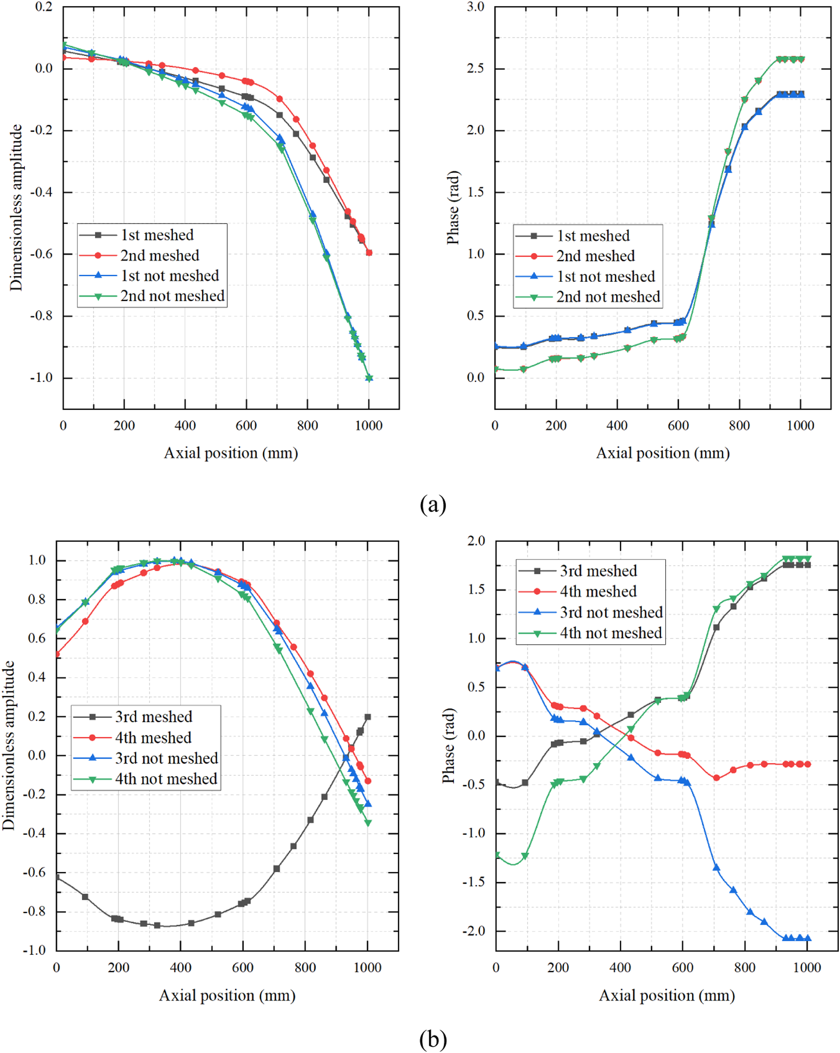
As shown in Tables 2 and 3 and Figures 5 and 6, incorporating gear-pair meshing coupling significantly increases the modal complexity of the multi-shaft geared rotor system. This coupling not only alters the natural frequencies, mode shapes, and phases of the individual shafts but also introduces numerous system-level natural frequencies exhibiting distinct strongly and weakly coupled characteristics. Mode shapes and phases of individual shafts under shared Mode 11.
Orthogonal experimental design
Orthogonal experimental parameters.

Influence of parameters on modal characteristics
Orthogonal experimental data.

Influence of power on modal characteristics
The influence of power variation on the natural frequencies of the rotor system is shown in Figure 7. The results indicate that the natural frequencies of each order increase with rising power, exhibiting a positive correlation; the derived coupled (shared) natural frequencies follow the same trend. Regarding the kinetic energy ratio under shared frequencies, that of H1 shows a decreasing trend, while BGC exhibits an increasing trend. All characteristic variations demonstrate weakly nonlinear behavior. Influence of power ratio variation on modal characteristics.
Influence of rotational speed on modal characteristics
The influence of rotational speed variation on the natural frequencies is presented in Figure 8. It can be seen that the natural frequencies of all orders decrease with increasing speed ratio, showing a negative correlation, a trend also followed by the derived coupled (shared) natural frequencies. Regarding the kinetic energy ratio under shared frequencies, that of H1 increases with the speed ratio, whereas BGC first decreases and then increases. All characteristic variations exhibit weakly nonlinear behavior. At a speed ratio of 1, three-shaft shared natural frequencies appear in test runs 24 and 36. The corresponding kinetic energy distributions are 30.6 % (H1), 30.5 % (BGC), and 38.9 % (H2) for the first case, and 12.9 % (H1), 17.6 % (BGC), and 69.5 % (H2) for the second. In these instances, the kinetic energy share of H2 increases while those of H1 and BGC decrease, a pattern consistent with the trend observed in Figure 8 at the speed ratio of 1. Influence of speed ratio variation on modal characteristics.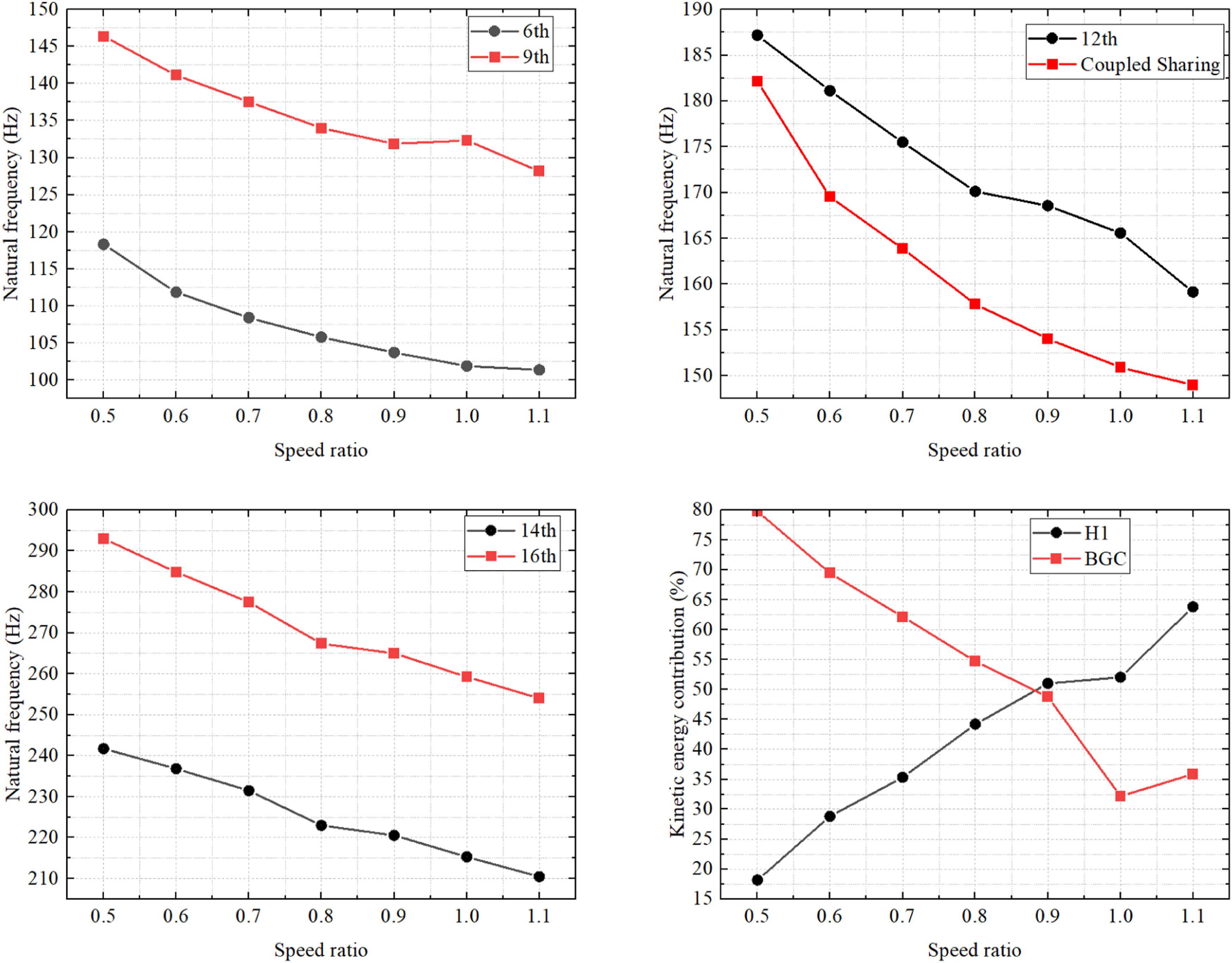
Influence of inlet oil temperature on modal characteristics
The influence of inlet oil temperature variation on the natural frequencies is shown in Figure 9. The data demonstrate that as the oil temperature changes, some natural frequencies (e.g., orders 6, 9, 12, and the coupled frequencies) follow a pattern of increasing, then decreasing, then increasing again, and finally decreasing. In contrast, other frequencies (e.g., orders 14 and 16) exhibit the opposite trend. For the kinetic energy ratios of the shafts under shared natural frequencies, both H1 and BGC show a pattern of decreasing, increasing, decreasing, and then increasing again. All observed trends demonstrate considerable variability. Influence of inlet oil temperature variation on modal characteristics.
Sensitivity analysis
Range analysis.

Variance analysis
Analysis of variance table.

Multiple linear regression prediction model
Drawing from the parameter variation patterns illustrated in Figures 7 and 9 and the orthogonal experimental data provided in Table 5, a multiple linear regression model was developed to predict the natural frequencies of different orders, the coupled (shared) frequency, and the kinetic energy ratios within the studied parameter ranges.
Define y i as the i-th natural frequency of the rotor system, where i ≤ 30. In addition, let y31, y32, and y33 denote the shared modal frequency, the kinetic energy ratio of the H1 and the BGC shaft, respectively. The independent variables are defined as x1 for PR, x2 for SR, and x3 for IOT.
For the i-th dependent variable, the following relationship is formulated:
Let:
Hence, the multiple linear regression model takes the following form:
Regression coefficients.


Comparison between fitted and experimental results.
Engineering case validation
To acquire vibration data from the rotor systems of the multi-shaft IGC, operational data were collected for the rotor system with the parameters listed in Table 1. The schematic diagram of the established test procedure is shown in Figure 11. The vibration acceleration measurement points are located at the H1 bearing housing in the X and Y directions (orthogonal, i.e., 90° apart), and the sampling frequency range is set to at least four times the maximum operating rotational speed. The shaft vibration measurement points are located near the bearing positions of H1 and H2 on the motor side, and the sensor type is a non-contact eddy current sensor. Schematic diagram of data acquisition.
The captured frequency-domain and time-domain vibration characteristics allow for targeted analysis. In this case study, the operating conditions during data acquisition were: SR= 1, PR = 1, and IOT = 36 °C. The frequency-domain and time-domain vibration data obtained under these conditions for the X and Y directions are shown in Figures 12 and 13, respectively. Frequency-domain plots. Time -domain plots.

Figure 12 reveals that the frequency-domain data contain peaks corresponding to the rotational speeds of the individual rotors, as well as frequency components arising from system-level natural frequencies induced by gear meshing. The measured value (158 Hz) shows an error of 1.8 % relative to the computed value (155.2 Hz) and an error of 1.1 % relative to the predicted value (156.3 Hz), which validates the accuracy of both the computational model and the regression prediction model. Although the vibration amplitude associated with the coupled frequency is relatively low, it still contributes a noticeable share to the overall response. This demonstrates that in practical engineering applications, the coupling effect introduced by gear meshing cannot be neglected.
Under operating conditions with a PR of 0.7 and an IOT of 44 °C, the multi-shaft IGC was regulated by reducing the SR from 1.0 to 0.7. During this process, the monitoring system captured the shaft vibration data for H1 and H2. The curves of vibration amplitude versus speed ratio are shown in Figure 14. It can be observed that the critical speed ratios for both H1 and H2 are 0.72, corresponding to rotational frequencies of 135.9 Hz and 172.1 Hz, respectively. Each resonant frequency corresponds to the 9th and 12th natural frequencies of the rotor system. As derived from the multiple linear regression model equation, the predicted frequencies for this operating condition are 136.1 Hz and 173.0 Hz, with errors within 1 Hz. This result further validates the accuracy of the prediction model. Based on this model, the inherent characteristics of the IGC rotor system under CAES variable operating conditions can be predicted, thereby providing a theoretical foundation for system control strategies. Vibration curves of the H1 and H2.
Conclusion
Variable operating conditions pose a significant challenge to the stability of multi-shaft IGC rotor systems used in CAES. This study investigates the evolution of natural frequencies and mode shapes of the rotor system under both single and variable operating conditions, accounting for multi-gear meshing coupling effects. The sensitivity of inherent characteristics to key control parameters is analyzed, and a multiple linear regression model is developed and validated against engineering data. The main findings are summarized as follows. (1) Before and after multi-gear-pair meshing coupling, the natural frequencies and mode shapes of each rotor undergo noticeable changes, while several new coupled shared natural frequencies are generated, making the modal behavior of the rotor system more complex. (2) Under variable operating conditions, rotational speed and power have a significant influence on the modal characteristics of the rotor system, mainly reflected in variations in frequency values and kinetic energy distribution, following a weakly nonlinear trend. The parameters are ranked in descending order of sensitivity as: rotational speed, power, and inlet oil temperature. (3) Vibration data collected from the engineering case validate the accuracy of the developed multiple linear regression prediction model, which provides important guidance for the design of multi-shaft IGCs used in CAES under variable operating conditions.
Footnotes

Author contributions
Jizhe Mao was responsible for data curation and drafting the initial manuscript. Yongchao Yuan conducted the formal analysis and applied software tools. Jianning Gong provided critical review and editing of the manuscript. All authors approved the final version.
Funding
The authors disclosed receipt of the following financial support for the research, authorship, and/or publication of this article: This work was supported by the Key R&D Program Project of Shandong Province, China (Grant Nos. 2023CXPT108 and 2024CXPT038).
Declaration of conflicting interests
The authors declared no potential conflicts of interest with respect to the research, authorship, and/or publication of this article.
Data Availability Statement
The datasets used and analyzed during the current study are available from the corresponding author on reasonable request.