
Abstract
Additive manufacturing (AM) methods such as fused filament fabrication (FFF) and direct ink writing (DIW) enable the free-form design and printing of complex architectures using a range of materials. Compared with traditional manufacturing technologies, AM methods are highly automated to reduce waste, assembly costs, and processing errors. By combining different AM deposition methods, we can fabricate composite materials with desired spatial arrangements and anisotropies to meet unique design requirements and to produce integrated multi-material components that are not easily manufactured by traditional strategies. To address a wide variety of mechanical performance requirements, developing hybrid AM technologies into a low-cost, fully-automated manufacturing process can realize a number of new types of elastomer composite architectures. In this work, FFF and DIW methods have been combined to fabricate thermoplastic polyurethane (TPU) reinforced silicone composite materials. Several specimens with different silicone and TPU infill patterns have been designed to characterize the mechanical compression responses of these structures. With 40–80% infill percentages of silicone and 20–60% infill percentages of TPU, composites specimens can be designed to get any specified compression response between 600 N and 9000 N. This TPU-reinforced silicone printing technique can be applied for silicone composite architecture design in a wide range of applications that require tunable elastic responses.
Introduction
Silicone elastomers, also called polysiloxanes, have a wide range of applications in soft robotics, 1 flexible electronics, 2 sealing structure, 3 and smart aerospace devices 4 because of their useful thermal stability, biocompatibility, bio-implantability, and electrical insulation properties. As conventional manufacturing technologies for silicone-based components, injection molding and casting have limited future development and potential range of new applications due to the slow curing speeds and high manufacturing costs associated with these processes. 5 An innovative method for silicone parts, additive manufacturing (AM), enables precise, fully-automated, consistent, predictable, and rapid direct fabrication process of architecturally structured silicone elastomers. 6 Thus, smart devices and structures can be developed with higher complexity, better integrity, and multiple materials options compared to conventional processing of silicones. 7 Several silicone 3D printing technologies such as vat photopolymerization, direct ink writing (DIW), and freeform reversible embedding, have been applied to build geometrically complicated elastomeric structures. 8 As one of the most commonly used AM methods, DIW is based on a nozzle dispensing system with a large deposition range from low viscous liquids to thick pastes. Current DIW research focuses on printability improvement for mass production and industrial scale-up. 9 Ink formulation and rheology studies are particularly critical for realizing printability in several advanced applications such as organ on a chip, biomedical implants, soft sensors, and superabsorbent materials.10–13
Multi-material DIW can be realized with various ink formulation combinations and multiple extrusion nozzles integrated into one system. The extrusion systems and printheads can be redesigned to switch or mix different materials in a single pass. 14 Techniques for dispersing particles and short fibers throughout elastomer base materials have been developed to generate better thermal and electrical conductivity, 15 printability, and UV curability. 16 To combine high levels of stiffness, strength, and toughness together in a single composite material, continuous fiber reinforcement 3D printing has been executed with impregnation, 17 co-extrusion, 18 and in-situ consolidation processes. 19 Additionally, multi-nozzle systems with 3D motion calibration are designed and integrated into 3D printers. Impregnation and co-extrusion based print heads have been further designed with droplet generator 20 and active mixer 21 functions. Feedback control systems have been applied with CCD cameras. 22 DIW with a two-stage curing method has also been investigated to use thermoset materials in 3D printing for enlarging the range of functional applications. 23 Moreover, a hybrid AM system combined DIW and fused filament fabrication (FFF) has been designed for electro-chemical products such as supercapacitors. 24
3D printed soft composite structures under various conditions of mechanical loading can be found in applications such as in sealing devices, isolation structures, and biomedical equipment. Bio-inspired sealing discs designed for small diameter pipes have been 3D printed with an aim towards future developments in pipeline inspection gauges. 25 As a common sealing structure, O-rings have been multi-material 3D printed with the development of microfluidic devices. 26 The mechanical performance of components like O-rings can be adjusted by tuning the proportions of the constituent materials. 27 For elastomeric isolation structure design, seismic isolators can be 3D printed using FFF technology, which allows for rapidly evolving design and component improvement. 28 Researchers used FFF 3D printers to fabricate pentamode lattice structures for exhibiting energy dissipation capacity and damping effect. 29 Among the biomedical applications, novel self-supporting microfluidic elastomer structures have been developed and 3D printed for viscoelastic inks precision extrusion, which has wide micro-scale applications such as lab-on-a-chip diagnostics, DNA microarrays, and cell-based assays. 30 Compliant and free-standing structures such as patient-specific heart models and bifurcating arterial structures can be also printed since soft elastomers can provide excellent biocompatibility. 31
As the most common class of 3D printing materials, thermoplastics are used in a wide range of FFF 3D printers. Thermoplastic materials become soft and pliable upon heating, and revert back to the glassy state after cooling. 32 Facile extrusion, a large variety of colors and transparency, no adhesives, and low cost make thermoplastic materials more competitive in several 3D printing technologies in addition to FFF such as selective laser sintering 33 and multi jet fusion. 34 But combinations of silicones and thermoplastics in 3D printing is a challenge since hard and soft materials have adhesion issues and often incompatible printing processes. Hybrid manufacturing processes have been created to cast silicone onto a 3D printed mold with mechanical interlocking. 35 Silicone networks can be improved and controlled for better adhesion performance with thermoplastics. 36 As chemical adhesion methods, primer and plasma treatment can be applied to the contact surface between silicone and thermoplastics. 37 Generally, most research studies have focused on combining conventional manufacturing technologies with 3D printing technologies, and adhesion improvements. However, complicated composite structures with various volume ratios and infill patterns have not yet been explored. Also, current hybrid manufacturing processes for silicone and thermoplastics are not fully automated processes. Automated manufacturing processes have great potential for quickly responding to different mechanical performance requirements and production of custom parts. This work is motivated by the need to create customized multi-material elastomers with architected properties.
This study reports the development of thermoplastic polyurethane (TPU) reinforced silicone composite materials and presents several silicone-TPU architected elastomeric prototypes, which outline the possible mechanical properties achievable with this type of printing technology and composite elastomer construction. A series of disk-shaped specimens with a TPU reinforcement core inside a silicone shell are presented and investigated to evaluate the mechanical compression response of silicone composites. CT scanning and SolidWorks simulations are applied for compression characterization of these composite specimens. Finally, a number of prototype composite elastomeric components are demonstrated to show the utility of this work which can be extended to specific target applications.
Methods
Materials
Ninjatek Cheetah TPU Filament (NinjaTek, Manheim, PA) was used as TPU reinforcement, which has a printing temperature of 228°C. A printable, high-quality silicone elastomer, Primetech AMS3302 silicone (Primetech Silicones, Inc. Riverside, CA) was employed as a model DIW silicone ink. 38 To obtain good flow rheology, the silicone was heated to approximately 85–90°C in the pressurized ink dispenser during the printing process. After printing, the composite parts containing silicone were completely cured at 185°C for 2 h without deformation of the TPU. This curing process led to no slumping of the silicone structures and full silicone cure as assessed by achieving Shore A 50 durometer of the silicone.
3D Printer design
The dual print head design assembly is shown in Figure 1. For silicone printing, a high-pressure piston (HPx High Pressure Dispensing Tool, Nordson EFD, Westlake, OH) and a pneumatic-based high precision controller (Ultimus V, Nordson EFD, Westlake, OH) were used with a maximum pressure of 100 psi (7 bar). For TPU printing, LulzBot Taz 5 1.75 mm Single Extruder Tool Head (Aleph Objects, Inc. Loveland, CO) was installed into LulzBot TAZ Dual Extruder Mount v1 (Aleph Objects, Inc. Loveland, CO). The base for the dual extrusion AM machine is a LulzBot TAZ 5 3D Printer (Aleph Objects Inc. Loveland, CO). The development details of the dual 3D printing process have been reported in previous work.39–40 (a) Fully assembled dual print head; (b) Fisnar nozzle for silicone printing and copper nozzle for TPU printing; (c) Fisnar nozzle and syringe tube for silicone printing.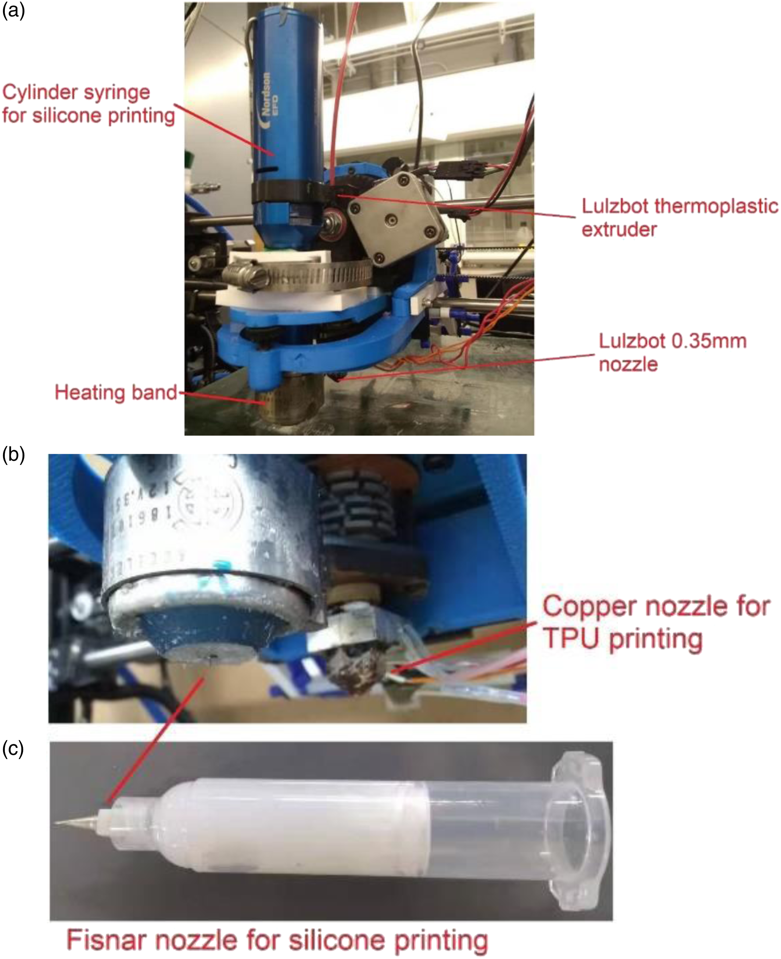
Mechanical testing
TPU reinforced silicone composites were investigated for their mechanical compression response and TPU reinforcement effects. Three kinds of disk-shaped compression specimens based on the ASTM D575 standard were printed: pure silicone specimens with different infill patterns, pure TPU specimens with different infill patterns, and silicone-TPU composite specimens. Each specimen had the dimensions noted in Figure 2. Photographs of the pure silicone specimens with different infill percentages are shown in Figure S-1. The infill pattern for these specimens was selected in Cura as rotated lines, in which every four layers have four different line directions, 0°, 45°, 90°, 135° (Figure S-2). Pure TPU specimens were printed with a 0°/90° alternating layer grid infill pattern (Figures S-3 and S-4). The silicone and TPU infill patterns were different because the grid pattern gave good results in TPU for varying infill percentages, but the low zero shear viscosity of the silicone required more supporting structures (the rotated lines) to obtain good print quality. For composite specimen printing, infill percentages of silicone were set from 40% to 80%, since 90–100% infill specimens trapped air inside the specimens and experienced swelling after curing, as shown in Figure S-5. Infill percentages of TPU were set from 20% to 60% to maintain good printing quality and to achieve a range of mechanical strengths with reasonable print times. Composite specimens based on the ASTM D575 standard: (left) silicone infill percentage >40% (right) silicone infill percentage = 40%.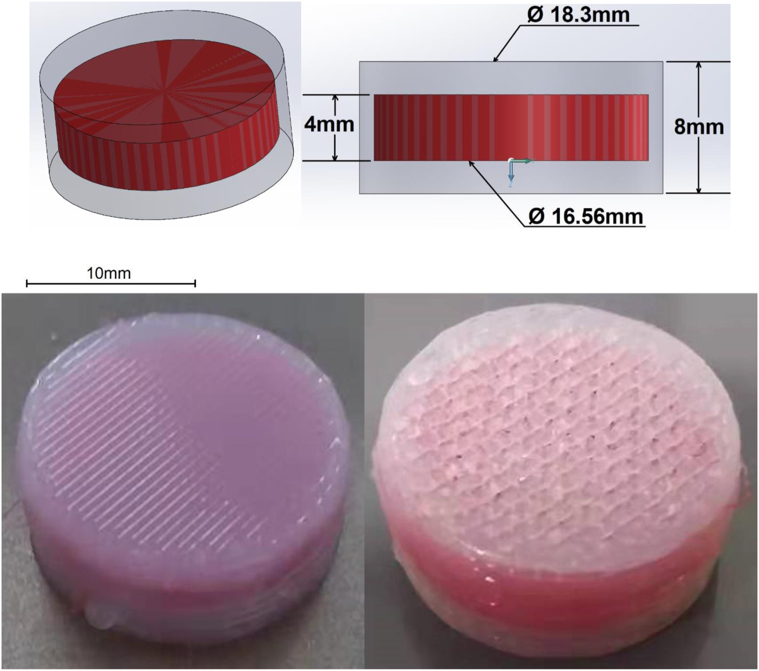
All of the specimen sizes have been reduced from the ASTM standard size of Ø28.6 mm × 12.5 mm to Ø18.3 mm × 8 mm, with the same aspect ratio, obtain a reasonable printing time of less than 4 hours. Composite specimens have a sandwich structure with a TPU core being printed between two parts of silicone (6 layers silicone +11 layers TPU with two lines of silicone walls outside +6 layers silicone), see Figure 2. We keep the same thickness for silicone and TPU to ensure that they almost have the same volume ratio in the composite specimens. In the middle section of the specimen, the TPU core is fully covered by a silicone side wall with a 0.87 mm thickness. Since the silicone section of specimens was 3D printed by a 25-gauge, 0.437 mm precision dispensing nozzle (Fisnar Micron-S, Fisnar Inc. Wayne, NJ), the TPU core will be covered with a two-layer side wall. Thus the TPU core will be locked inside the specimen, which can minimize the lateral displacement of the TPU core during the compression test. Compression tests were performed at ambient temperature (∼20°C) on MTS (Eden Prairie, MN) Criterion® Electromechanical Test System equipped with 10 kN load cell with 12 mm/min compression speed. The mechanical compression response of the specimens and TPU reinforcement effect were evaluated by comparing single materials and composite specimens with different infill percentages of TPU and silicone.
Results and discussion
The disk-shaped compression specimens shown in Figure 2 were printed by the dual-extrusion printer. The silicone section of specimens was 3D printed by a 25-gauge, 0.437 mm precision dispensing nozzle (Fisnar Micron-S, Fisnar Inc. Wayne, NJ) with 2.05 mm/s printing speed, 85°C printing temperature, 1 mm layer height, and an extrusion pressure of 99 psi. The TPU section of the specimens were printed by a LulzBot 0.35 mm copper nozzle (Aleph Objects, Inc. Loveland, CO) with 25 mm/s printing speed, 228°C printing temperature, and 0.35 mm layer height. The typical printing process is shown in Figure S-6.
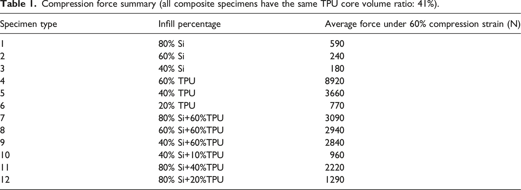
Compression force summary (all composite specimens have the same TPU core volume ratio: 41%).
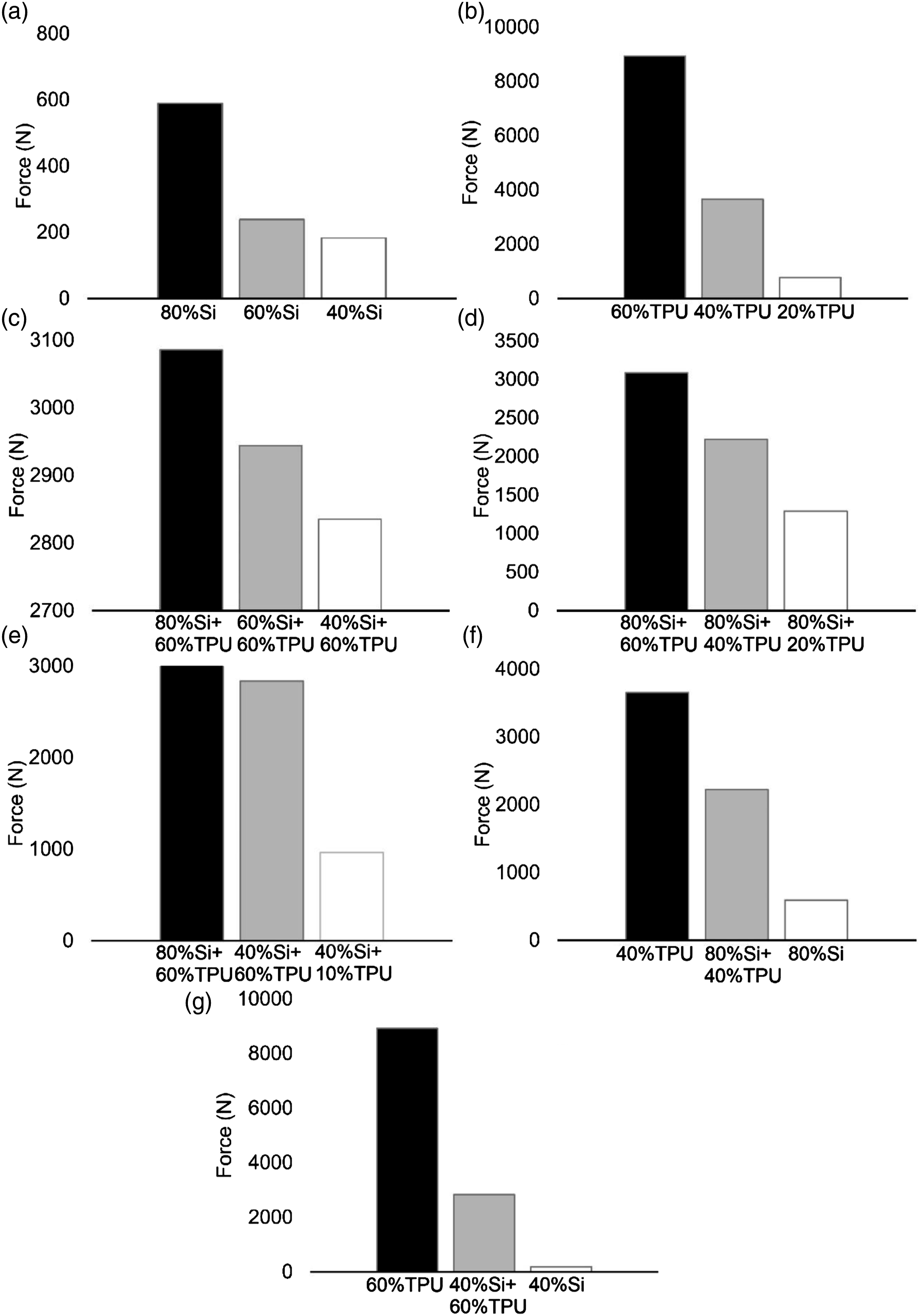
Specimens’ compression force comparison at 60% compression (All the composite specimens have the same TPU core volume ratio: 41%).
To demonstrate the utility of our approach, specimen types 1, 5, 11 and 3, 4, 9 present the effect of modifying the TPU core on the response of the composite specimens, as shown in Figure 3 (f) and (g). Pure TPU specimens (type 4 and 5) showed high compression force at 60% compression strain (with 60% infilled pure TPU specimens reaching 9000 N with 60% compression strain). However, pure silicone specimens (type 1 and 3) showed no more than 600 N compression force under these conditions. Thus, based on design requirements, composites specimens can be designed to get any specified compression response between 600 N and 9000 N. Specimen type 9 (40% infilled Si + 60% infilled TPU) and 11 (80% infilled Si+40% infilled TPU) displayed intermediate compression force values of 2840 N and 2220 N at 60% compression.
Finite element analysis (FEA) of these structures was performed using a SolidWorks non-linear simulation. In the simulation, one compression plate was subject to a 4.8 mm displacement along the compression direction to match the 60% compression strain of experimental results. As an example, SolidWorks simulation setups for 80% infilled pure silicone specimen and 80% infilled silicone +60% infilled TPU specimen are shown in Figure S-7. Typical simulation results of strain and stress distributions are shown in Figures S-8 and S-9, in which the TPU reinforcement effect can be observed. The force versus displacement curves from simulations show that 80% infilled pure silicone specimen and 80% infilled silicone +40% infilled TPU composite specimen showed similar compression curves to the experimental compression test results, as shown in Figures S-10 and S-11. Although the simulation stops at 45–55% compression strain due to the mesh size limitation, the simulation results show a good correlation to the experimental test results.
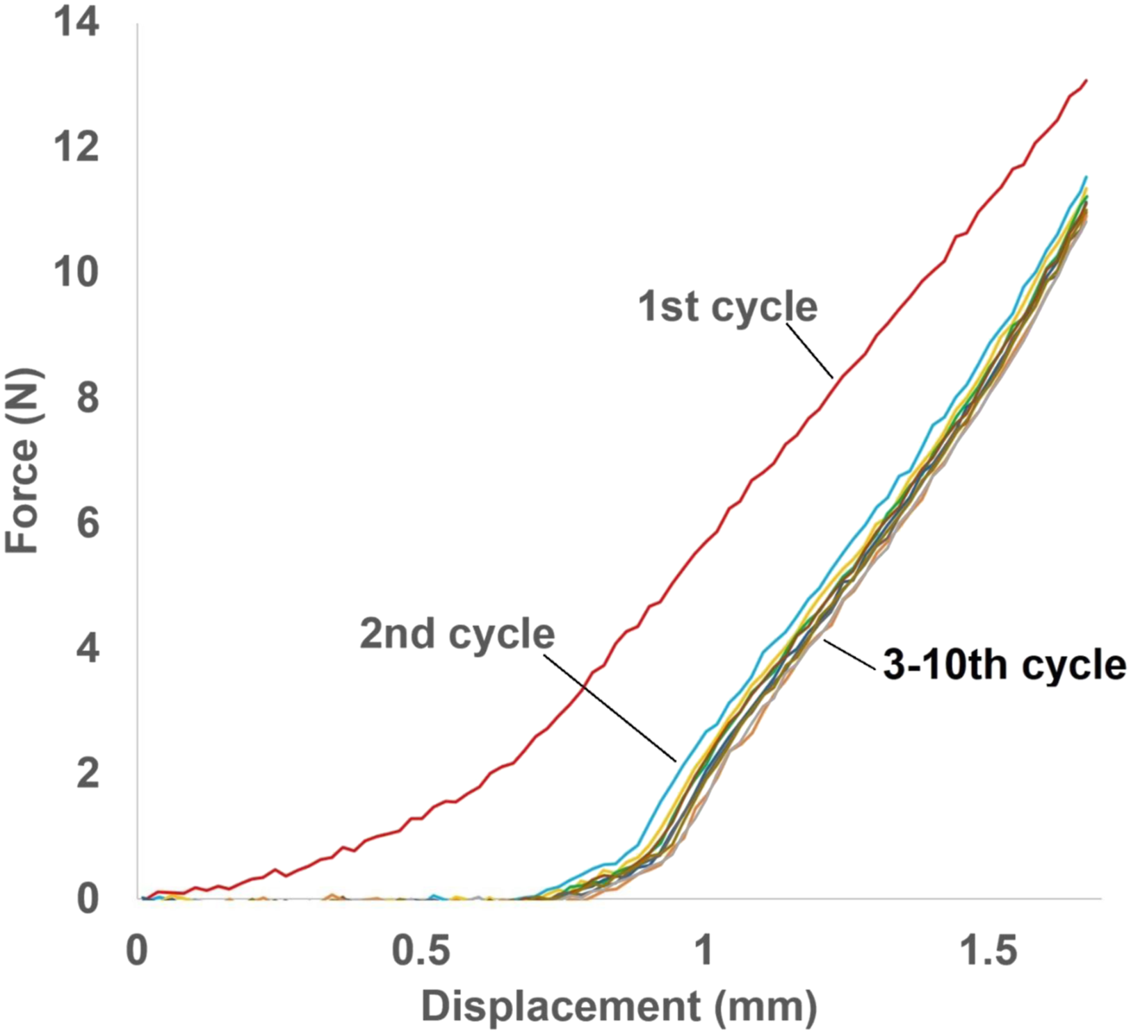
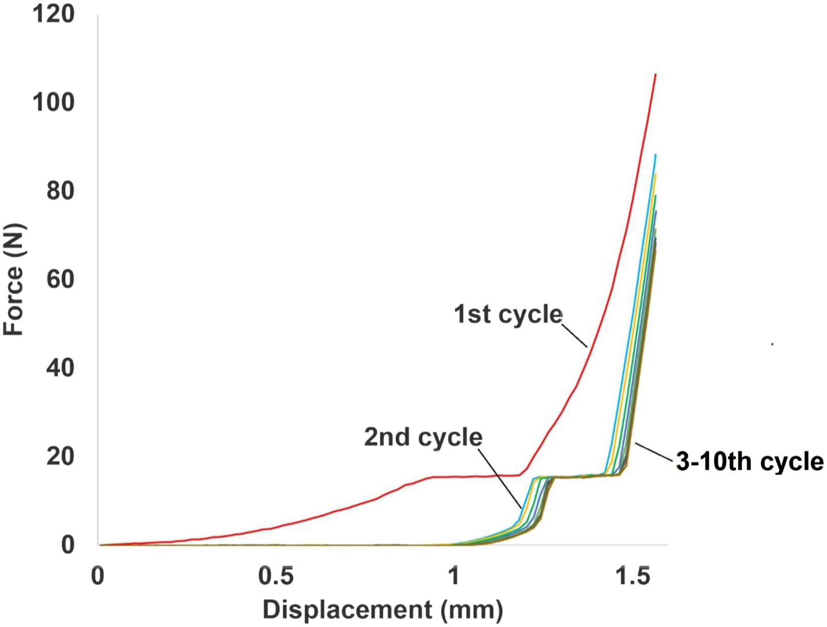
Figures 4 and 5 show the cycling test results with 20% and 60% compression strains for elastic/plastic deformation evaluation of 40% infilled silicone specimens. Although compression responses show hysteresis due to the Mullins effect ,
41
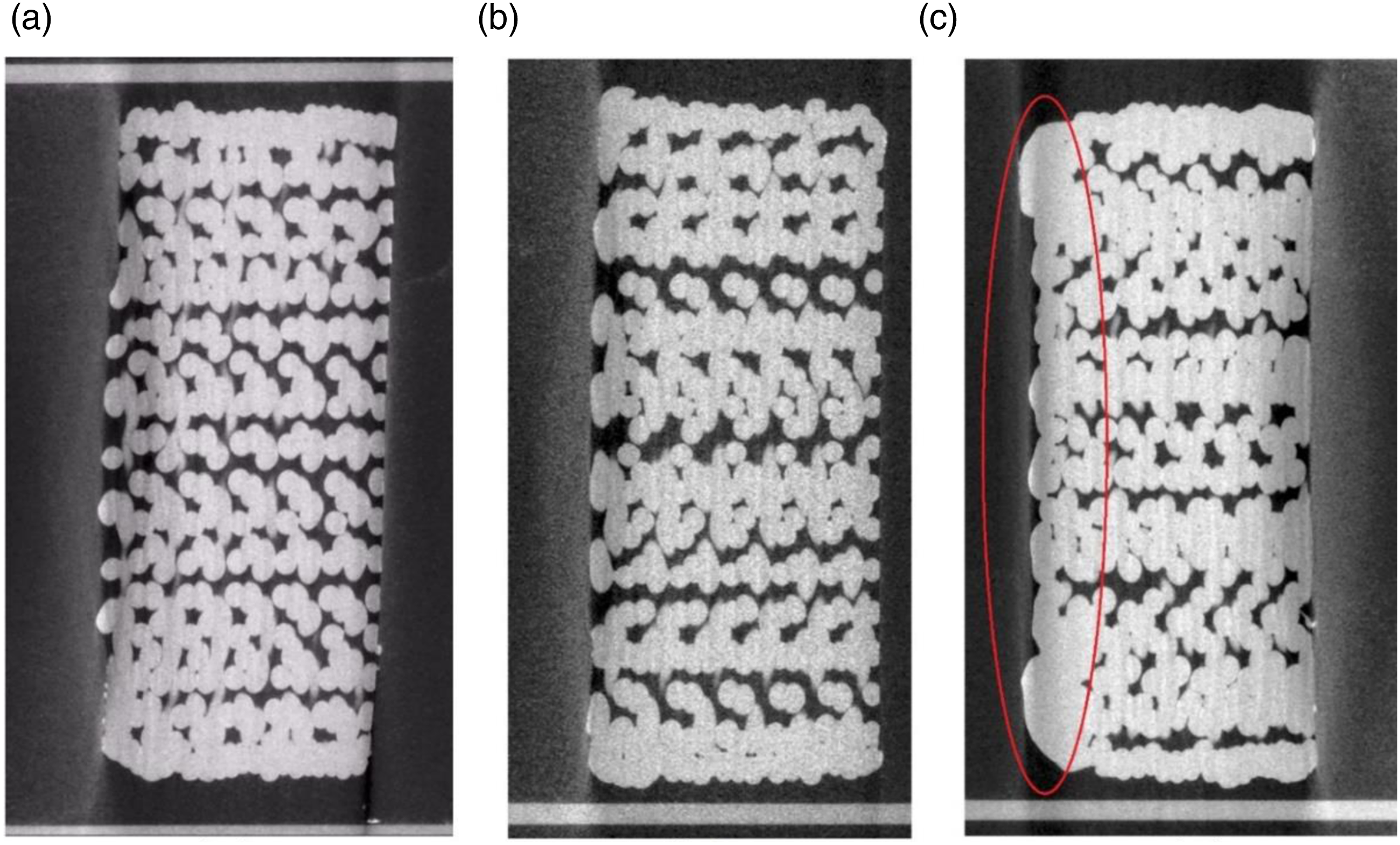
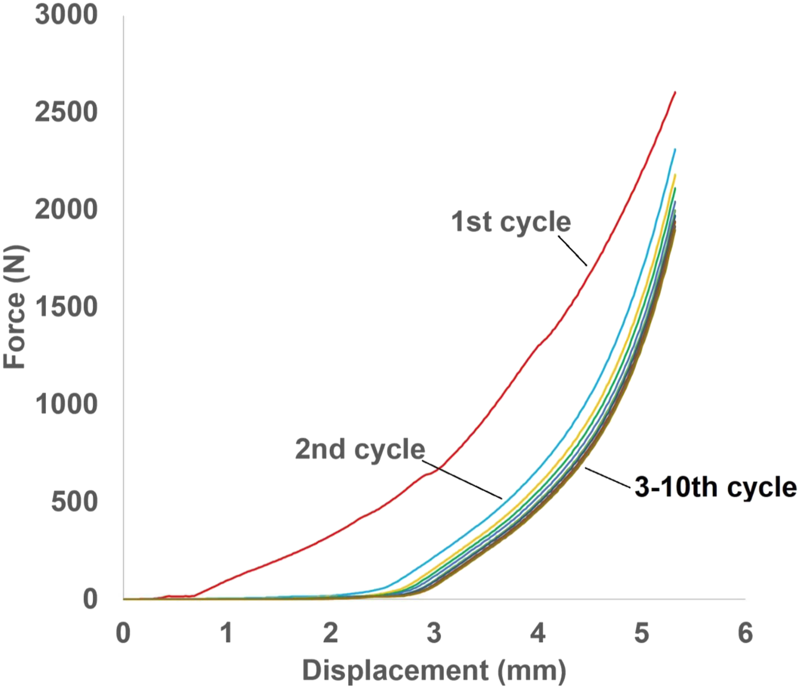
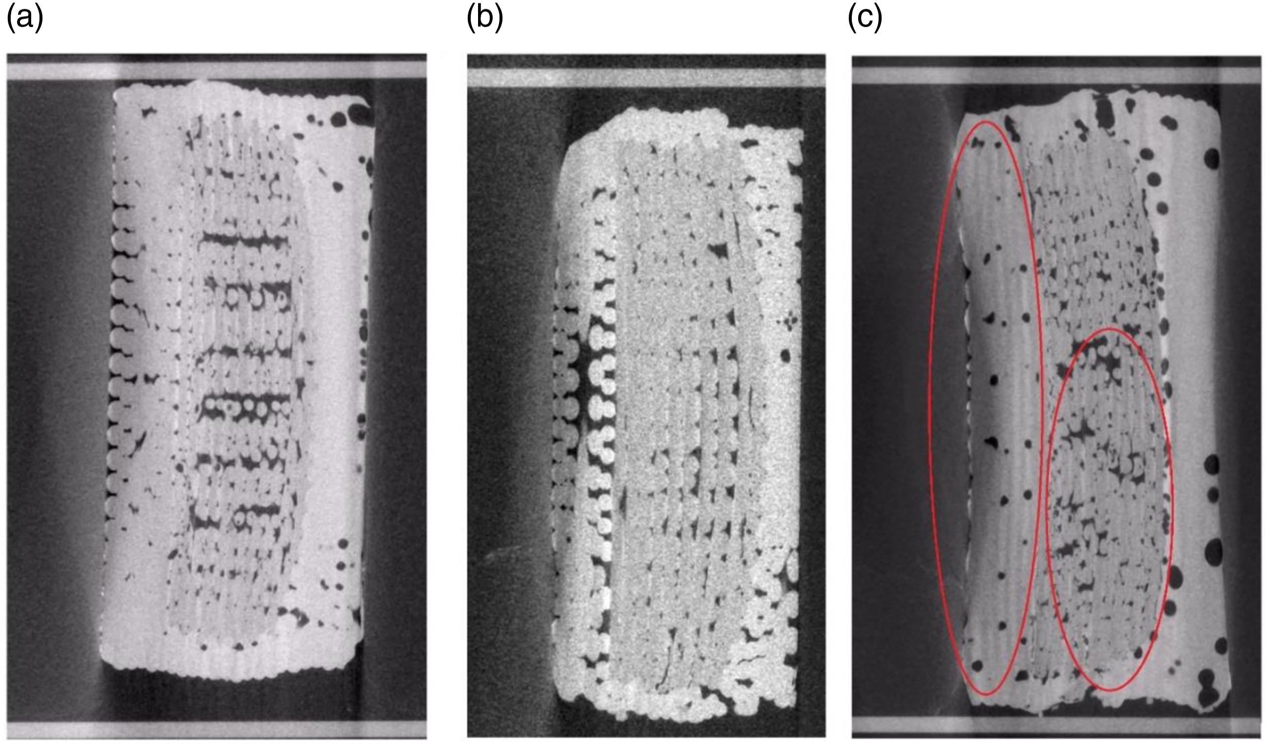
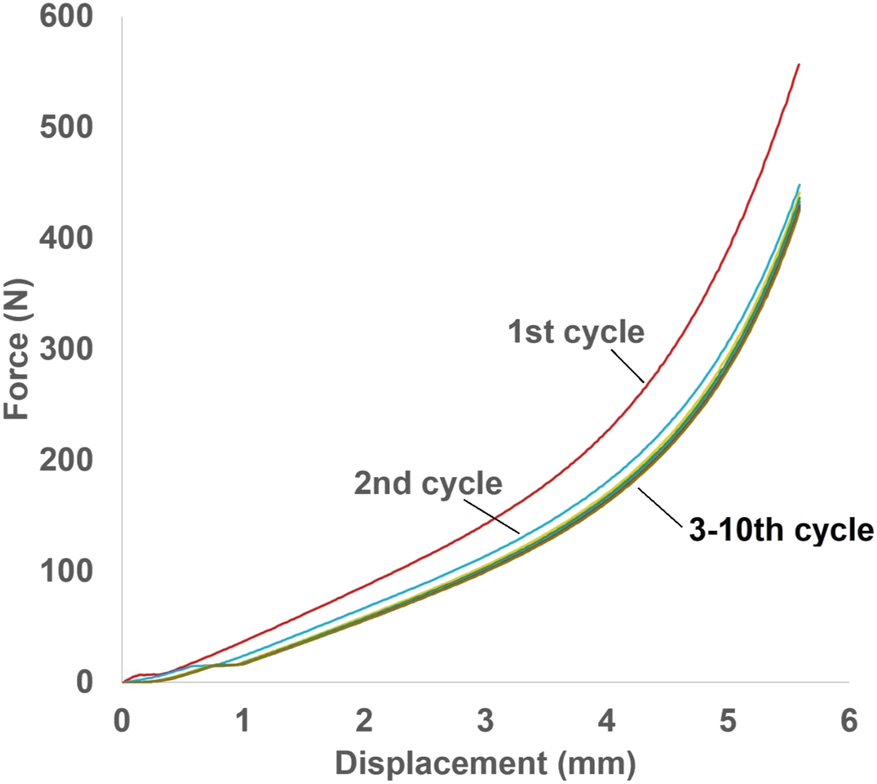
all the specimens demonstrate good elasticity with no clear reduction in compression force with cycling. The hysteresis phenomenon after 20% compression is smaller than the phenomenon after 60% compression. To explain the hysteresis phenomenon, Figure 6 shows the CT scan results of 40% infilled pure silicone specimen before compression and after 20% and 60% compression. This specimen has no large differences in morphology comparing the as-printed and after 20% compression tests, but a permanent set occurred after 60% compression tests. The CT results tend to show that the silicone layers near the top surface stick to each other and collapse the structure. Figures 7 and 8 show the cycling test results with 20% and 60% compression strains for elastic/plastic deformation evaluation of 60% infilled silicone +60% infilled TPU composite specimens. Compared with 60% compression, the hysteresis phenomenon was reduced by 50% in the 20% compression tests. Figure 9 shows the CT scan results of 60% infilled silicone +60% infilled TPU composite specimen before compression and after 20% and 60% compression. This specimen also has a permanent set that occurred after 60% compression. Silicone layers near the top contact surface stick together, also the TPU core is damaged after 60% compression. So compared Figures 4 and 7, composite specimens have a larger hysteresis phenomenon because of plastic deformation and damage in the TPU core. Finally, several 80% infilled silicone specimens were subjected to 60% compression tests. A typical result is shown in Figure 10 that shows no hysteresis. This data indicates that the hysteresis phenomenon can be minimized by increasing the silicone infill percentage, and that composite specimens have good mechanical properties under small compression strain, but suffer damage under larger compression deformation. The other cycling test results are presented in Figures S-17 and S-18. Cycling compression test result of 40% infilled silicone specimens (60% compression). Cycling compression test result of 40% infilled silicone specimens (20% compression). CT scanning results of 40% infilled silicone specimen: (a) initial (b) after 20% compression (c) after 60% compression. Cycling compression test result of 60% infilled silicone +60% infilled TPU specimens (60% compression). Cycling compression test result of 60% infilled silicone +60% infilled TPU specimens (20% compression). CT scanning results of 60% infilled silicone +60% infilled TPU specimen: (a) initial (b) after 20% compression (c) after 60% compression. Cycling compression test result of 80% infilled silicone specimens (60% compression).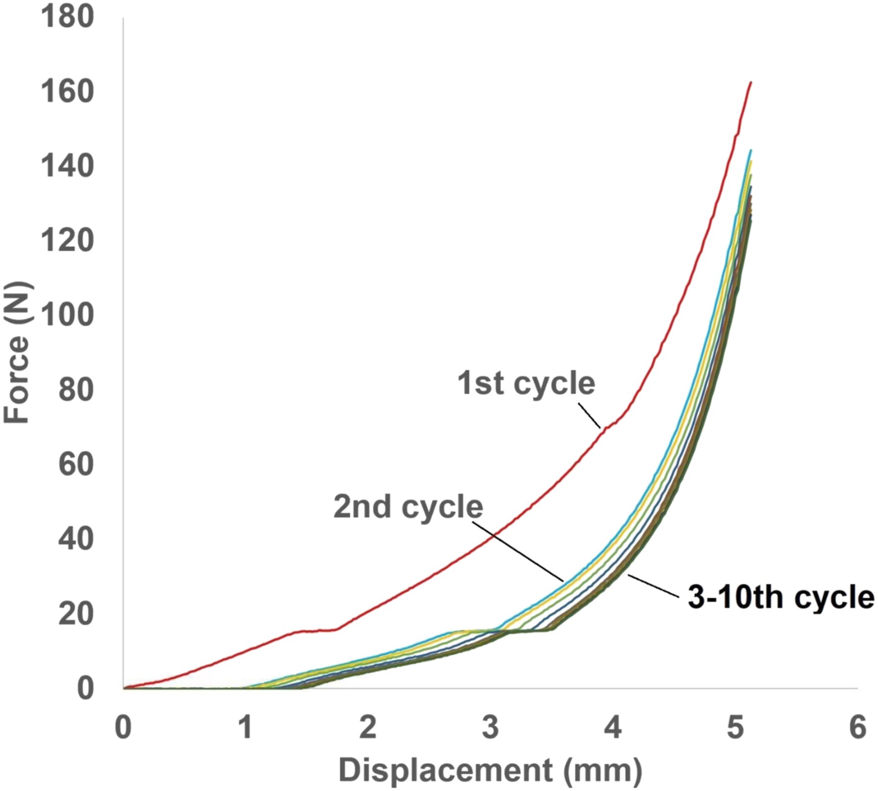
Demonstration parts with TPU reinforcement printing
To demonstrate TPU reinforcement printing in silicone-based structures, two parts were printed using TPU along with a silicone matrix. As one of the most common sealing structures, D-shape components were printed to demonstrate the feasibility of printing silicone with TPU reinforcement in different infill percentages. Additionally, the printing feasibility of more complex structures with TPU reinforcement was also investigated. As an example, a uniquely-shaped sealing structure for a rotary liner hanger bearing
42
was printed. The TPU reinforcement core for these two structures were designed and 3D printed as shown in Figure 11. A series of the D-shaped sealing structures are printed: 80% infilled Si + 40% infilled TPU, 80% infilled Si + 20% infilled TPU, 40% infilled Si + 40% infilled TPU, 40% infilled Si + 20% infilled TPU. Then four types of infill pattern combinations have been printed: 80% infilled Si + 40% infilled TPU, 80% infilled Si + 20% infilled TPU, 40% infilled Si + 40% infilled TPU, 40% infilled Si + 20% infilled TPU. The TPU reinforcement can be printed by following the geometric interior features of the structures. For these structures, the mechanical response and reinforcement effect can be tuned by changing the infill percentage and reinforcement core geometry. Two kinds of sealing structures: D-shaped specimens: (a) 80 % infilled Si (white) + 40 % infilled TPU (red), (b) 80 % infilled Si + 20 % infilled TPU, (c) 40 % infilled Si + 40 % infilled TPU, (d) 40 % infilled Si + 20 % infilled TPU. Special-shaped specimens: (a) 80 % infilled Si + 40 % infilled TPU, (b) 80 % infilled Si + 20 % infilled TPU, (c) 40 % infilled Si + 40 % infilled TPU, (d) 40 % infilled Si + 20 % infilled TPU.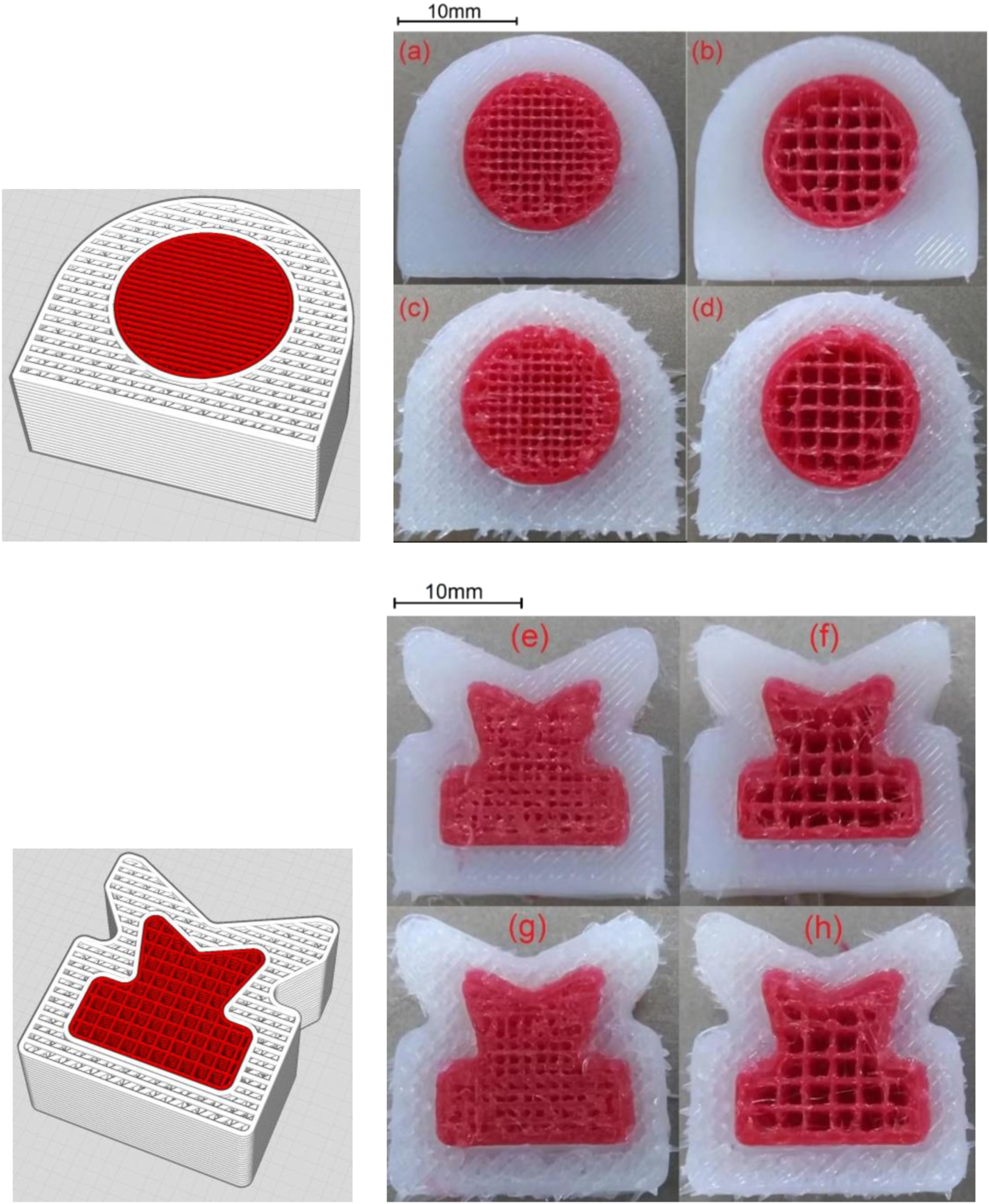
Conclusions
In summary, a series of TPU reinforced silicone specimens have been developed using multi-material AM. Compression test mechanical property experiments were designed to investigate the functional properties of disk-shaped structured specimens, which have also been analyzed by CT scanning and FEA simulation. Desired compression strength can be freely designed by adjusting the TPU reinforcement ratio and infill percentages of TPU and silicone. Several prototypes were 3D printed to outline the printing feasibility of TPU reinforcement effects (20–60% infill percentage) for various silicone elastomeric architectures (40–80% infill percentage) with different mechanical properties requirements. To widen the range of possible applications for these types of structures and to provide better reinforcement effects, future work may attempt to integrate novel thermoplastic, silicones, and support materials for producing composite architectures with more complicated geometries and tuned mechanical performance. Future work will also investigate the 3D printing orientation effects to demonstrate mechanical properties variations with orientation and validate composite architecture design flexibility.
Footnotes
Acknowledgements
We would like to acknowledge funding from Greene, Tweed & Co. for this work.
Declaration of conflicting interests
The author(s) declared no potential conflicts of interest with respect to the research, authorship, and/or publication of this article.
Funding
The author(s) disclosed receipt of the following financial support for the research, authorship, and/or publication of this article: This work was supported by Greene, Tweed & Co.
Supplemental Material
Supplemental material for this article is available online.
References
Supplementary Material
Please find the following supplemental material available below.
For Open Access articles published under a Creative Commons License, all supplemental material carries the same license as the article it is associated with.
For non-Open Access articles published, all supplemental material carries a non-exclusive license, and permission requests for re-use of supplemental material or any part of supplemental material shall be sent directly to the copyright owner as specified in the copyright notice associated with the article.