
Abstract
Ultrasonic welding is a promising technology to join fibre-reinforced thermoplastic composites. While current studies are mostly limited to fabric materials the applicability to unidirectional materials, as found in aerospace structures, would offer opportunities for joining primary aircraft structures. However, due to the highly anisotropic flow of a molten unidirectional ply undesired squeeze flow phenomena can occur at the edges of the weld overlap. This paper investigates how the fibre orientation in the plies adjacent to the weld line influences the welding process and the appearance of edge defects. Ultrasonic welding experiments with different layups and energy director configurations were carried out while monitoring temperatures at different locations inside and outside the weld overlap. The joints were characterized by single lap shear tests, analysis of corresponding fracture surfaces and microscopic cross-sections. Results showed that the anisotropic flow and the anisotropic thermal conductivity of the plies adjacent to the weld line have a distinct effect on the appearance and location of edge defects. By using energy directors that cover only part of the weld overlap area a new approach was developed to mitigate edge defects caused by the highly directional properties of the unidirectional plies.
Introduction
Joining technologies are key to exploit the full potential of fibre reinforced thermoplastic composites from single part manufacturing to assembled structures. Ultrasonic welding is a promising technology to join those fibre-reinforced thermoplastic composites. The process is characterized by low-amplitude and high-frequency vibrations that are applied transversally to the welding surface.1,2 Heating occurs at the weld interface, first by frictional heating, followed by viscoelastic heating of the polymer, resulting in short heating times and low energy consumption. 3
Due to its lower stiffness compared to the fibre-reinforced adherends, heat is generated mostly in the so called energy director.4–7 An energy director is a thin element of neat polymer that is placed between the adherends. The energy director can be a triangular protrusion moulded on one of the adherends, 7 a thin polymer film, 5 or a polymer mesh. 8
Ultrasonic welding can be a static or a continuous process. The static process is characterized by a vibration phase and a consolidation phase. In the vibration phase a static pressure and ultrasonic vibrations are applied by the sonotrode to melt the polymer of the adherends and the energy director. 6 During the consolidation phase the static pressure is kept without further vibrations to allow for solidification of the molten polymer to obtain void-free joints. In continuous ultrasonic welding the two phases cannot be distinguished. The sonotrode and the adherends move relative to each other, creating a continuous weld. 9
The ultrasonic welding process is applicable to a wide variety of polymers and reinforcement fibres (e.g. glass fibres and carbon fibres). Most studies were performed on PPS, 5 ,10,11 PEI,4,12 and PEEK. 6 They focused on fabrics as reinforcement architectures and little work has been done on unidirectional materials. The focus of the studies using unidirectional fibres also was on the simulation of heating mechanisms and squeeze flow 6 and using ultrasonic spot welding for tacking of plies during the layup of preforms. 13
Unidirectional materials are preferred in the aerospace industry for highly loaded components such as fuselage and wing structures. Due to the absence of crimp, associated to textile architectures, unidirectional materials have high strength and stiffness. Developing and understanding the ultrasonic welding process for unidirectional materials would extend its potential application to primary aerospace structures.
If unidirectional laminates are used, the stacking sequence and the fibre orientation at the joining interface are important for the load transfer between the adherends which is dominated by transverse shear and peel stresses and hence for the mechanical behaviour of the joint. 14 The stacking sequence can be expected to distinctly influence the static lap shear strength as well as the fatigue behaviour of the welded joint. The highest static lap shear strength is observed with fibres oriented in the same direction as the loading.15,16 In contrast, a 45° interface ply improves the fatigue strength and resistance to crack propagation. 17 Those conclusions are based on adhesively bonded adherends. But, since the failure never occurred in the adhesive layer similar results can be expected for welded joints, where failure also usually occurs in the plies adjacent to the weld line.
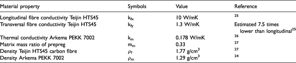
Apart from the mechanical properties, also thermal properties depend on the stacking sequence and ply orientation adjacent to the weld line. During ultrasonic welding heat transfer is important and differences can have an impact on the welding process. Due to their anisotropic graphitic structure, carbon fibres show high thermal conductivity along the fibre direction while the conductivity is low perpendicular to the fibre direction. 18 Hence, the thermal conductivity within one unidirectional ply of the composite depends on the fibre orientation and the fibre volume fraction and can be estimated based on the rule of mixtures. 19 Ageorges et al. calculated the longitudinal and transversal thermal conductivity for an APC-2 PEEK laminate. 20 They reported a longitudinal thermal conductivity which is 17 times larger than in transversal direction.
In ultrasonic welding the energy director has the role to focalize the frictional and viscoelastic heating. Flat energy directors are preferred for thermoplastic composites and were used in many studies.10,21,22 Villegas et al. compared traditional neat resin protrusions and so-called flat energy directors. 5 Flat energy directors, which are loose layers of neat polymer placed at the welding interface prior to the welding process, performed equally well in single lap shear tests and showed a wider processing window.
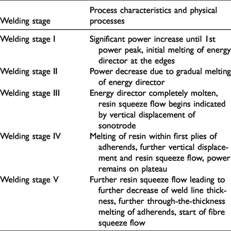
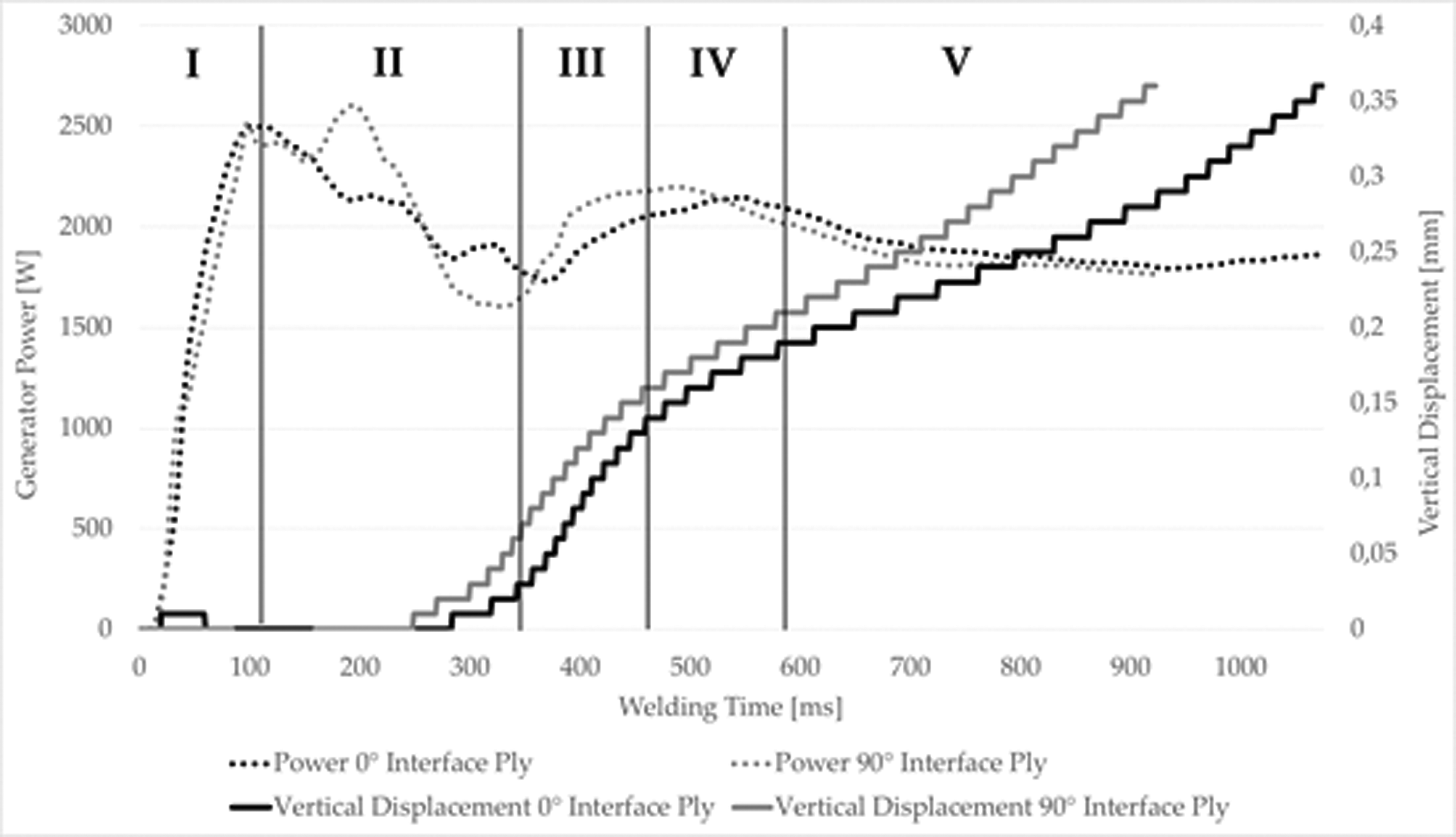
The static ultrasonic welding process allows for in situ monitoring by using different process data. Villegas investigated the relationship between process data and lap shear strength. 4 , 12 She concluded that vertical displacement of the sonotrode can be used to control the process and achieve high-strength welds. The welding process itself can be divided in several stages as described in Table 1. In the first welding stage the energy director starts melting preferably at the edges of the welding area. In the continuation of the process the energy director further melts through random nucleation and rapid growth of hot spots (stage II). After the complete melting of the energy director squeeze flow occurs in combination with a downward or vertical displacement of the sonotrode (stage III). Stage IV is characterised by further squeeze flow and melting of the resin within the first plies of the adherends. Usually a power plateau occurs. In stage V the thickness of the weld line further decreases and fibres are squeezed out. 4
Welding stages during static ultrasonic welding of fabric reinforcement as described by Villegas. 4
While most knowledge on ultrasonic welding of thermoplastic composites has been acquired with fabric reinforcement, specific effects have been observed while using other welding techniques on composites with unidirectional reinforcement. Dubé et al. investigated resistance welding of a skin/stringer joint, built from unidirectional fibre reinforcements. 23 Using optical microscopy to analyse the weld line they identified defects (voids) at the edges of the weld overlap and in the adjacent plies of the adherends. Nevertheless, the centre of the weld overlap showed no defects. They related this effect to the polymer squeeze flow out of the weld line. The voids in the adherends were related to the lack of consolidation pressure in the cooling phase as a consequence of the polymer squeeze flow. 23 Such defects might also occur during ultrasonic welding, especially as polymer squeeze flow is also present.
The study of Dubé et al. did not consider the fibre orientation especially adjacent to the weld line. 23 In general the effect of the fibre orientation on heat generation and heat transfer during the welding of unidirectional composites has not been addressed to the knowledge of the authors.
This paper aims to investigate how the fibre orientation in the plies adjacent to the weld line influences the welding process and the appearance of defects at the edges of the weld overlap. Specific focus is put on heat generation and heat transfer due to the anisotropic thermal conductivity and anisotropic flow of unidirectional materials. This is investigated by ultrasonic welding experiments with and without thermocouples placed in the weld line. Different energy director configurations are used. The analysis is based on single lap shear tests, corresponding fracture surfaces and microscopic analysis of cross-sections of the weld line.
Materials and experimental procedures
The material used in this study was Tenax®-E TPUD PEKK-HTS45 unidirectional prepreg tape with a fibre areal density of 194 g/m2 from Teijin Carbon Europe (former Toho Tenax Europe). Two different laminate layups were stacked by hand layup. The plies were tacked by local welding at several points using a hot tool. The two different stacking sequences consisted of 12 plies prepreg tape with a single ply thickness of 0.18 mm resulting in a nominal thickness of 2.2 mm after consolidation. The fibre orientation with respect to the welding configuration is shown in Figure 1. The laminates are referred to as configuration 0° and 90° hereafter and have the following stacking sequence:
Configuration 0°:(0/45/135/90/45/135)s Configuration 90°:(90/135/45/0/135/45)s
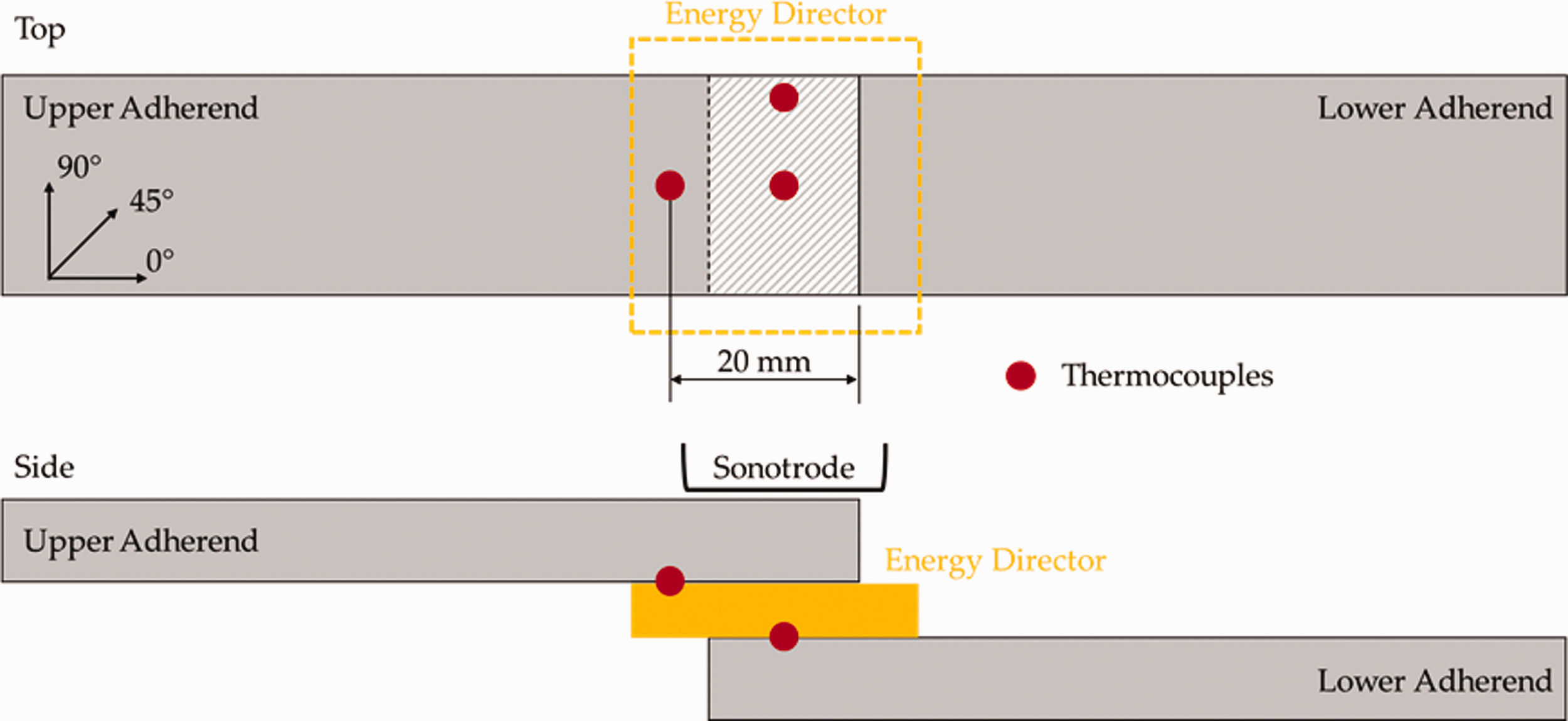
Schematic of position of thermocouples for temperature measurements during welding. Two thermocouples were placed within the weld overlap (edge and centre) while one was placed outside the weld overlap. The hatched area marks the welding area.
The laminates were consolidated in a hot-platen press at 365 °C for 10 min at 12 bar. A cooling rate of approximately 1.5 K/min was applied to assure the full crystallization of the polymer matrix. The laminates were scanned by ultrasonic inspection (A-scan) for voids and delaminations. Ultrasonic welding specimens (101.6 mm × 25.4 mm) were extracted from areas without defects by a water jet cutter. Samples were degreased and cleaned with acetone prior to welding.
The energy director was manufactured from 0.04 mm thick neat Arkema PEKK 7002 polymer film. Nine layers were stacked on top of each other to produce a 0.36 mm energy director. The layers were oven consolidated for 15 min at 250 °C, above the glass transition temperature, but below the melting point. Vacuum bagging and an aluminium caul plate were applied to assure a smooth surface and to allow for a differential pressure of 1 bar during oven consolidation. The applied temperature assured a proper connection of the individual layers without melt flow. The energy directors were cut to 30 × 30 mm2 pieces to be larger than the welding area or to 30 × 17 mm2 to cover only 66% of it. The energy director was chosen based on pre-trials using different energy director thicknesses. The 0.36 mm energy director showed preferential heating at the welding interface. Therefore it was used throughout the study.
Ultrasonic welding
A 20 kHz micro-processor controlled ultrasonic welder from Herrmann Ultraschalltechnik, Germany was used to weld specimens in a single-lap shear configuration according to ASTM D1002. The overlap area was 12.7 mm × 25.4 mm. A rectangular sonotrode with the dimensions 14.9 mm × 30 mm was used.
The ultrasonic welder has a maximum power output of 6.2 kW and can automatically adjust the power to keep the amplitude constant. The peak-to-peak amplitude was set to 86.3 µm. The welding and consolidation forces were set to 1000 N, corresponding to a pressure of 3.1 MPa for the nominal weld area. The force is applied through the sonotrode driven by a pneumatic actuator on a linear axis. After the vibration phase the specimens were allowed to cool down for 4000 ms before the consolidation force was removed. The ultrasonic welder enables controlling the welding process in three modes: heating time, energy controlled and vertical sonotrode displacement controlled. Following Villegas vertical displacement of the sonotrode was used throughout this study as the controlling parameter for the welding process. 12 An exception are experiments in which the welding process was prematurely stopped. In this case heating time was used to control the process.
The temperatures in the weld line were acquired using thermocouples with a diameter of 0.1 mm. The temperature measurements were synchronized with the welding process parameters power and sonotrode displacement and sampled at a frequency of 1000 Hz. The thermocouples were placed at three different locations as shown in Figure 1. Two thermocouples were placed in the weld overlap between the energy director and the lower adherend. The last one was placed on the upper adherend just outside the weld overlap. The positions of the thermocouples were chosen based on previous work where the highest temperatures in the interface were found at the longitudinal edges of the weld overlap. 3 Fibre optics and thermography were initially considered as alternative temperature measurement methods but discarded later on. None of those technologies are believed to be suitable to measure temperatures during the ultrasonic welding process since fibre optics might break due to the applied vibrations and the sonotrode blocks direct view on the weld overlap, which makes thermography inapplicable. Nevertheless, as a general rule for verification of the measurements obtained with just one type of sensors, measurements were performed in several specimens for each welding configuration and the consistency of the results was assessed.
The specimens were held in place by a custom-made jig (Figure 2). The jig prevented the specimens from moving sideways during the welding process but also allowed for vertical displacement of the upper adherend during the process by four springs.
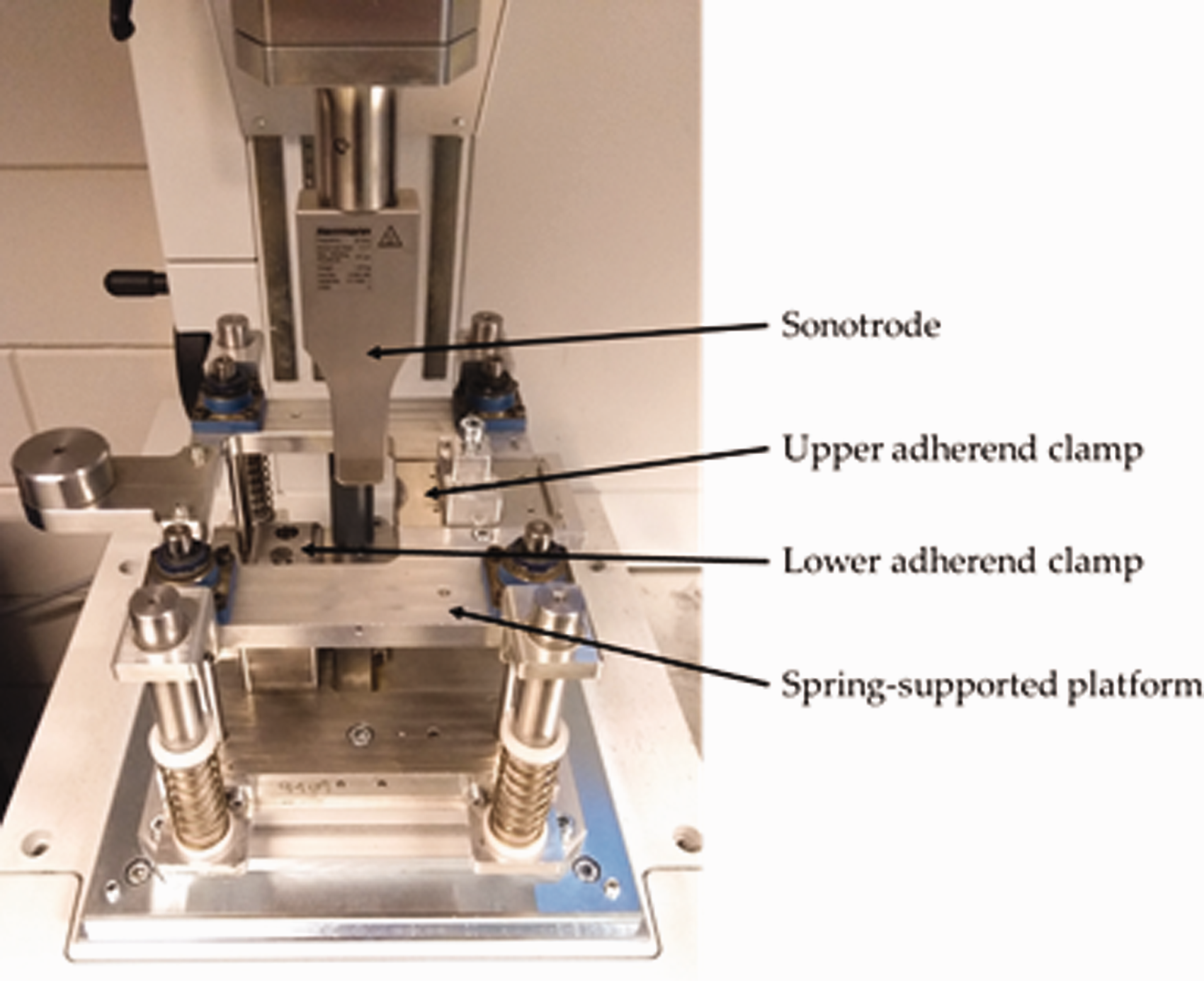
Ultrasonic welding jig used throughout the study. The jig allowed for vertical displacement of the upper adherend during the welding process by four springs.
At the beginning of the study the optimum displacement for the displacement-controlled welding mode was identified. As described in the studies of Villegas et al. this was done by performing welds using the thickness of the energy director (0.36 mm) as vertical displacement and observe the power-displacement curves provided by the ultrasonic welding machine. 4 , 12
Figure 3 shows the generator power and vertical displacement of the sonotrode during the welding process of configuration 0° laminates. The welding process was stopped once a vertical displacement of 0.36 mm (energy director thickness) was reached. As described by Villegas different welding stages can be distinguished which are related to different physical processes in the welding interface and summarised in Table 1. 4
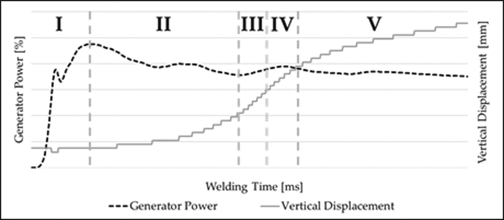
Representative power (black dashed line) and vertical displacement (grey solid line) curve with distinct welding stages: Stage I - initial energy director melting; stage II - gradual energy director melting; stage III - complete melting of the energy director and resin squeeze flow onset; stage IV - melting of first plies of adherends; stage V - decrease of weld line thickness and through-the-thickness melting of adherends.
The comparison to literature shows that the same stages are present in the ultrasonic welding of unidirectional materials than in the welding of fabrics. However, the characteristics of the stages are different. Especially stage IV, the stage were normally the highest lap shear strength values are achieved, is very short. It coincides with a vertical displacement of around 0.16 mm. Usually the stage shows a power plateau and increasing vertical displacement while for the welding of unidirectional materials the plateau is replaced by a 2nd power peak and a decline of the generator power which is an indicator for stage V. Based on this assessment 0.16 mm vertical displacement was identified as optimum value to control the process and is therefore used throughout this study.
Testing and evaluation
The welded single lap shear specimens were mechanically tested in a Zwick/Roell 250 kN testing machine following the ASTM D1002 standard. A crosshead speed of 1.3 mm/min was used. To assure parallelism between the weld line and the load path the hydraulic grips of the testing machine were offset. Five samples were tested per set of welding conditions. The lap shear strength was calculated based on the maximum load divided by the total overlap area (12.7 mm × 25.4 mm). The fracture surfaces were analysed by naked eye. The lap shear strength is the result of the welding process and is therefore important an aspect to fully characterize the influence of the fibre orientation on the welding process.
Cross-sectional microscopy was done on cut specimens to analyse the weld line and the adherends. The cross-sections were produced using a precision saw and subsequent polishing both along the load direction and perpendicular to the load direction.
Results and discussion
Influence of fibre orientation on the welding process
Stages of the welding process
The power-displacement curves of welds performed with configuration 0° and 90° show differences that are attributed to the fibre orientation adjacent to the weld line. Figure 4 compares the power-displacement curves of samples of each configuration welded with the same welding parameters and a vertical displacement of 0.36 mm. Both samples show the distinct stages of the welding process. The first stage up to the first power peak (as described in Table 1) is similar in heating time for both samples (ca. 100 ms). They also show a power decline as it is typical for welding stage II. The end of this stage is marked by a power minimum. The start of vertical sonotrode displacement, which is associated to the melting and squeeze flow of the energy director, appears earlier for configuration 90° (at 275 ms) compared to configuration 0° (at 340 ms). The total heating time (0.36 mm vertical displacement) for 90° configuration (930 ms) is 145 ms shorter than for configuration 0° (1075 ms). Although the differences seem not very large, throughout the study heating times for configuration 90° are in average 10% (±3%) shorter compared to configuration 0° if the same welding parameters are used.
Power (dotted line) and displacement (solid line) curves for configuration 0° (black) and 90° (grey) samples welded with 86.3 µm amplitude, 1000 N weld force (3.1 MPa) and vertical displacement of 0.36 mm. Approximate welding stages are separated by vertical lines. Configuration 90° shows earlier vertical sonotrode displacement and overall shorter heating time.
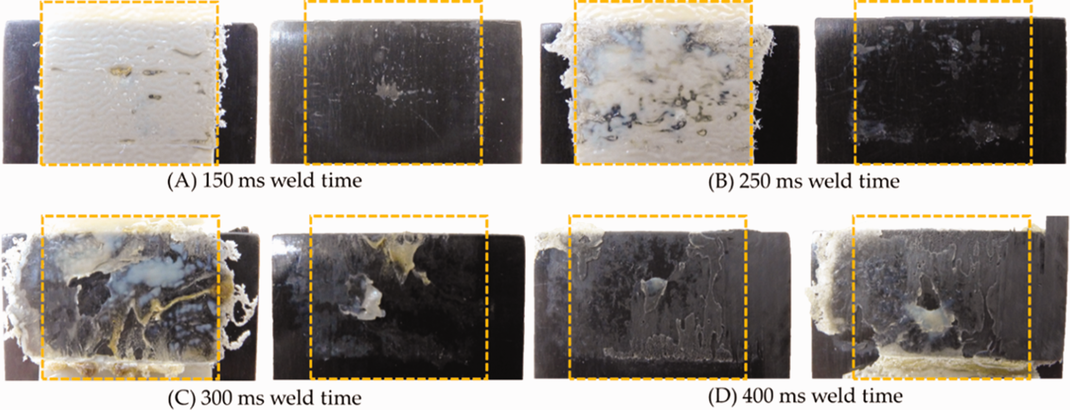
Fracture surfaces from samples at different heating times within stage II confirm the observations from the power-displacement curves. Figure 5 shows fracture surfaces of samples welded with 150 ms, 250 ms and 300 ms heating time, respectively. The lap shear samples are mechanically tested to obtain the fracture surfaces. At 150 ms (Figure 5 (A) and (D)) initial melting of the energy director (1st power peak) already took place at the longitudinal edges of the adherends and at random spots across the weld overlap. This is well in line with the knowledge from literature.
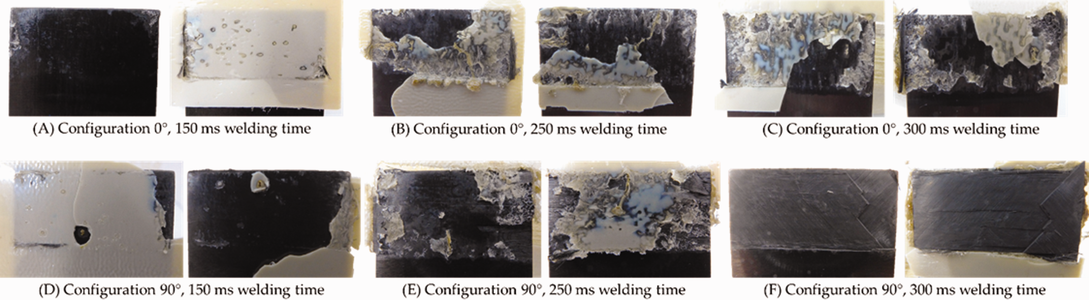
Fracture surfaces of samples welded with 150 ms, 250 ms and 300 ms heating time. Configuration 0° samples (A–C) show gradual melting from longitudinal edge to centre with unmolten energy director after 300 ms. Configuration 90° samples (D–F) show gradual melting of energy director and failure in 135° ply after 300 ms.
As the heating time increases, the amount of molten energy director increases while, at the same time, the centre of the weld overlap shows more unmolten energy director compared to the longitudinal edges. Up to 250 ms both configurations show similar fracture surfaces, however 300 ms (Figure 5 (C)), configuration 0° still shows unmolten energy director. The weld line for configuration 90° is however not visible in the fracture surface as failure occurred in the 135° ply underneath. But the corresponding power-displacement curve (Figure 6) already shows some vertical displacement indicating the complete melting of the energy director. Furthermore, some polymer squeeze out is visible at the perimeter of the weld overlap.
Power (dotted line) and displacement (solid line) curves of samples welded with 300 ms heating time (fracture surface C and F in Figure 5). Configuration 0° sample (black lines) shows no vertical displacement at 300 ms heating time. Configuration 90° sample (grey lines) shows beginning of vertical displacement after 250 ms. Curves are shifted vertically for better visibility.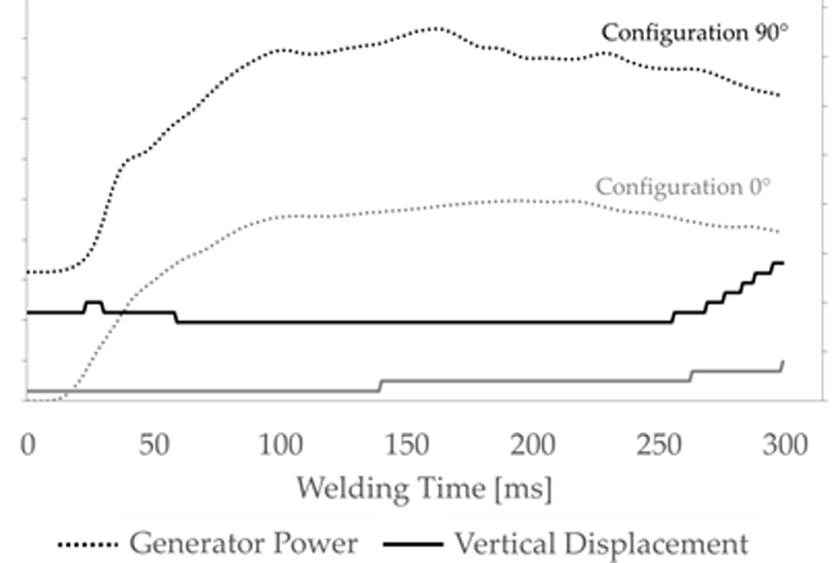
Temperature measurements
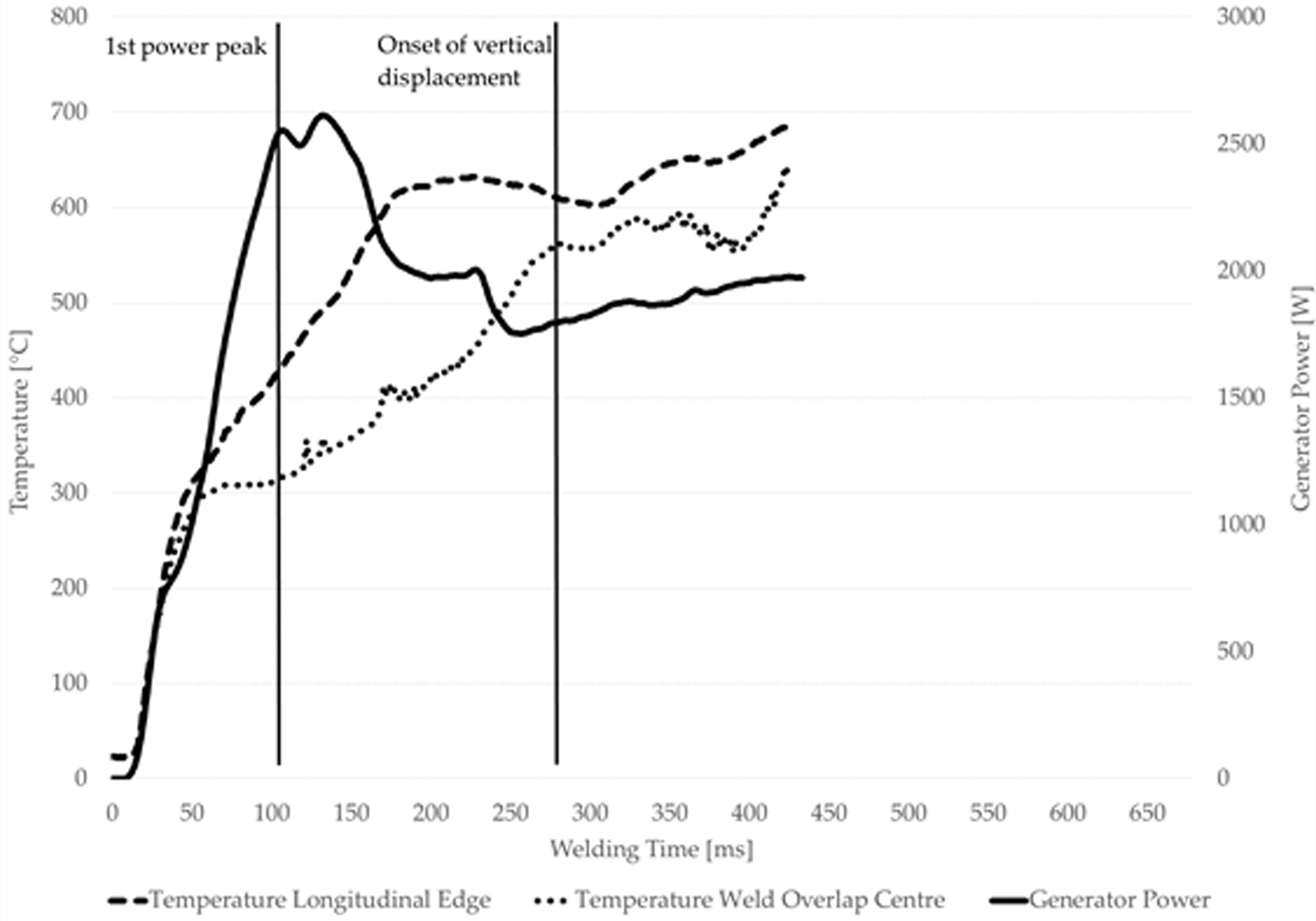
The differences between the two configurations during gradual melting of the energy director, from the longitudinal edges to the centre, can also be confirmed by the temperatures measured through the thermocouples during the welding process. Figures 7 and 8 show the temperature measurements as well as the corresponding power curves obtained during welding of configuration 0° and 90° samples. For both samples the same welding parameters are used. A vertical sonotrode displacement of 0.16 mm is chosen to achieve welding up to stage IV.
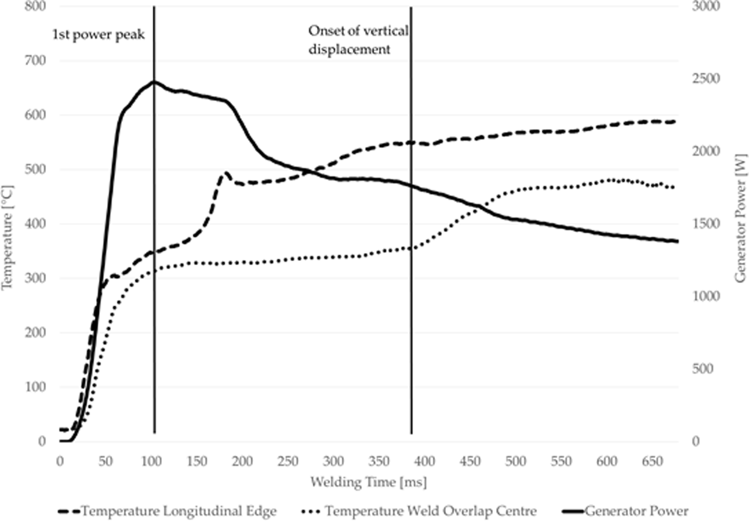
Temperature measurement at the weld overlap centre (dotted line) and longitudinal edge (dashed line) for configuration 0° sample. Welding performed with 86.3 µm amplitude, 1000 N weld force and 0.16 mm vertical displacement. Vertical lines indicate 1st power peak and onset of vertical displacement.
Temperature measurement at the weld overlap centre (dotted line) and longitudinal edge (dashed line) for configuration 90° sample. Welding performed with 86.3 µm amplitude, 1000 N weld force and 0.16 mm vertical displacement. Vertical lines indicate 1st power peak and onset of vertical displacement.
The temperatures in both configurations show a rapid increase to around 300 °C. Afterwards the heating rate declines but temperatures are still increasing. In both configurations the temperature difference between the longitudinal edge and the centre of the weld overlap increases after 300 °C. In case of the 0° configuration the difference remains between 150–180 °C almost until the end of the welding process. In contrast, the temperature difference shrinks significantly around the onset of vertical displacement for the 90° configuration. While a maximum temperature difference of around 200 °C is reached after 200 ms, the difference is limited to around 40 °C at the onset of vertical displacement. This temperature difference is maintained during the rest of the welding process. Furthermore, the comparison of overall maximum temperatures achieved during the welding process shows generally higher temperatures for configuration 90°. It should be noted that in both configurations the temperatures measured were significantly higher than typical temperatures used in processing of PEKK composites which are 340 °C–360 °C.24 This raises the question as to whether thermal degradation occurred in the PEKK polymer matrix. However, we believe that the occurrence of thermal degradation is prevented owing to short exposure (below 1s) of the material to such high temperatures.21 In fact the welded samples show no signs of degradation in the form of voids or dry fibres on the fracture surfaces. Likewise, the reader should note that the influence of the thermocouples themselves on the welding process is not fully understood. It cannot be ruled out that the presence of the thermocouples may influence the welding process and affect the measured vertical displacements, for instance. Furthermore the thermocouples are also exposed to the ultrasonic vibrations, especially the ones within the overlap. Therefore the initial rapid temperature increase to 300 °C might be an effect of localized frictional heating of the thermocouple itself rather than the actual temperature increase inside the weld line. After this first phase the energy director and the surface of the adherend starts to soften which most likely reduces friction with the thermocouple. As these potential errors are systematic, the monitored temperatures are still considered valuable to understand differences in the welding process for both configurations used in this study.
Heat transfer
The distinct temperature developments during the welding process are linked to heat generation and heat transfer and are dependent on the fibre orientation adjacent to the weld line. The beginning of stage II (at 100 ms) is characterised by an increasing temperature difference between the longitudinal edge and the centre of the weld overlap. The centre of the overlap is completely surrounded by the adherends and heat can be conducted into the adherends outside of the weld overlap which decreases the heating rate. The longitudinal edges are in contact with the surrounding air which limits heat conduction and in combination with the higher heat generation, due to less restrained slippage, the longitudinal edges show higher heating rates.
While the welding process continues the initial temperature difference is reduced for configuration 90°, but not for configuration 0°. This could indicate that heat conduction from the longitudinal edge to the centre of the overlap plays a more important role in configuration 90°.
It should be noted that within one ply of a unidirectional composite material the in-plane thermal conductivity is different along and transversal to the fibre direction. The thermal conductivity within one ply of a composite laminate can be estimated by the rule of mixtures. 20 It depends on the thermal conductivity of the fibres (longitudinal and transversal), the thermal conductivity of the matrix (isotropic) and the fibre volume content. In case of the used Tenax®-E TPUD PEKK-HTS45 the properties can be estimated as summarized in Table 2. Data for the transverse fibre thermal conductivity is rare in published literature. For carbon fibres it is estimated as 5–10 times lower than in longitudinal direction. 25 Here a value of 7.5 is used as no data from the material supplier is available.
Material properties of Tenax®-E TPUD PEKK-HTS45. If material properties are not available, data from similar materials is taken and referenced accordingly.
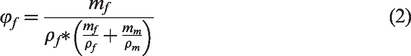
The fibre volume content (φf) and the matrix volume content (φm) are calculated based on the rule of mixtures for fibre volume content and the material properties given in Table 2:
28


The calculated fibre volume content of 0.59 and the matrix volume content of 0.41 are used to calculate the thermal conductivity within an individual ply of Tenax®-E TPUD PEKK-HTS45 using the rule of mixtures for thermal conductivity as suggested by Ageorges et al.
20

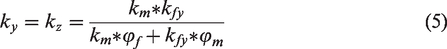
Using the formulas and the material properties from Table 2 the thermal conductivity within one ply of Tenax®-E TPUD PEKK-HTS45 is 5.94 W/mK parallel to the fibres (kx) and 0.36 W/mK transversal to the fibres (ky). Assuming that the material is transversely isotropic, ky is equal to kz. This means thermal conductivity along the fibres is 16.5 times higher than transversal to the fibres.
Because of the high thermal conductivity along the fibres (kx) heat is conducted into the adherends outside of the weld overlap instead of being conducted from the longitudinal edges to the centre of the weld overlap in configuration 0°. This results in a temperature differences during the complete welding process. On the other hand it leads to a temperature equalisation between the longitudinal edges and the centre of the weld overlap at the end of welding stage II for configuration 90° samples.
This is also confirmed when temperatures just outside the weld overlap, as shown in Figure 1, are measured. Figure 9 shows the temperature development outside the weld overlap for the same welds as shown in Figures 7 and 8. Both configurations show fast initial heating while the temperature remains almost constant for the rest of the welding process. But the temperature measurement in configuration 90° reaches a constant value of around 200 °C while for configuration 0° the temperature goes up to around 250 °C. The temperature differences are smaller compared to the ones within the weld overlap because further effects such as radiation and convection of heat in the surrounding area and conduction into the tool can be expected to have an increasing influence. But they nevertheless indicate the more prevalent heat transfer into the adherends outside the weld overlap for the 0° laminate configuration due to the better thermal conductivity along the fibres. This could also explain the generally lower temperatures at the longitudinal edges and the centre of the weld overlap for configuration 0° samples compared to configuration 90° as more heat is conducted into the adherends in the former case.
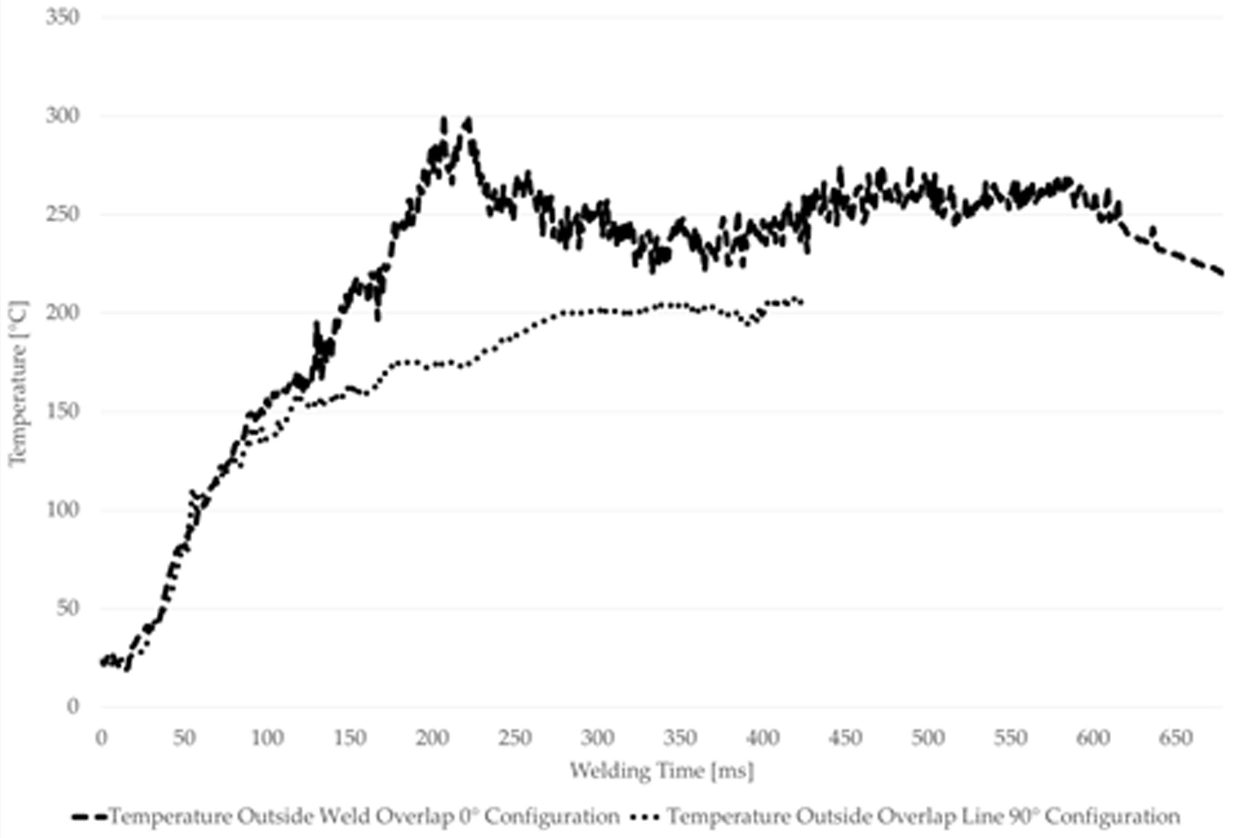
Temperature measurement outside the weld overlap on top of upper adherend for configuration 0° sample (solid line) and configuration 90° (dotted line). Welding performed with 86.3 µm amplitude, 1000 N weld force and 0.16 mm vertical displacement.
Appearance of edge effects due to different fibre orientations adjacent to the weld line
Edge defects
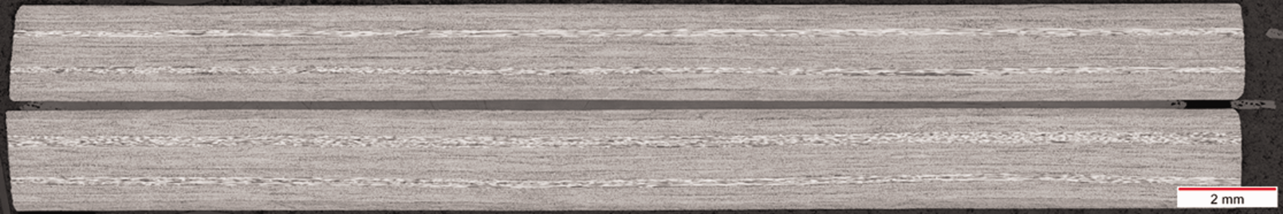
Different fibre orientations of the plies adjacent to the weld line reveal another effect. Especially for the 0° configuration extensive fibre squeeze out can be noted. The effect of fibre squeeze out is also known from fabric materials but usually appears in welding stage V. 4 When using unidirectional materials this effect can be observed much earlier (already in stage III and IV). Figure 10 shows two microscopic images of cross-sections of configuration 0° adherends welded with 0.16 mm vertical displacement (corresponding to welding stage IV). Especially at the longitudinal edges (transversal cut in Figure 10(A)) voids are clearly visible in the weld line as well as in the adherends. Furthermore polymer and fibre squeeze out can be seen. As seen in Figure 10(C) the area of voids have a somewhat triangular shape stretching into the first plies (i.e ply closest to the weld line) of each adherend. The longitudinal cut (Figure 10(B)) indicates the absence of voids in the centre of the weld line and shows no voids and squeeze out limited to the polymer from the weld line (i.e. energy director) in the transversal edges. Similar effects were report by Dubé et al. in resistance welding of unidirectional APC-2/PEEK. 23 They concluded that the voids are caused by the polymer flow leaving gaps which cannot be filled and insufficient consolidation pressure due to this polymer flow. In the case of ultrasonic welding both polymer and fibre squeeze out are present as visible in the micrographs. However the voids seem to be caused mainly by material flow leaving gaps which cannot be filled. Otherwise, if also the consolidation pressure were locally diminished, voids would also be visible in molten plies that are not directly affected by the fibre squeeze flow. Similar to the study of Dubé et al. the centre of the weld line does not show any defects. 23
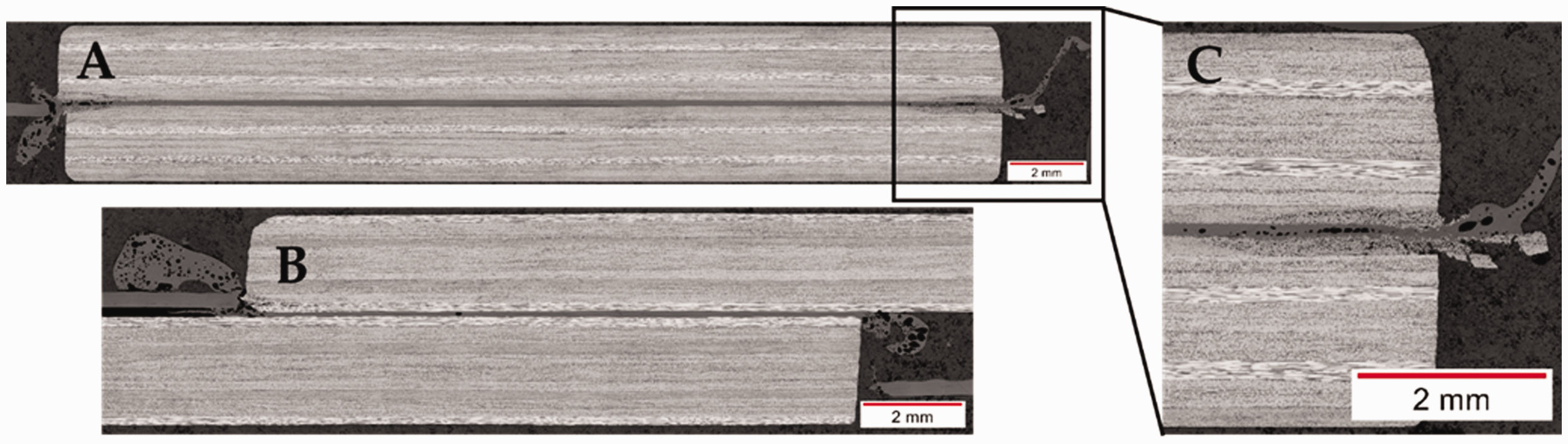
(A) Transversal microscopic cross-section of configuration 0° sample showing voids and fibre squeeze out in weld line and first ply of adherends. (B) Longitudinal microscopic cross-section of configuration 0° sample showing only polymer squeeze flow. (C) Detailed view on fibre and polymer squeeze out at right side of adherend (as indicated). For all microcuts: Centre of weld line is defect free. Welding parameters are 86.3 µm amplitude, 1000 N weld force and 0.16 mm vertical displacement.
Figure 11 shows the same type of microscopic cross-sections for configuration 90° samples. The samples were welded with the same welding parameters as configuration 0° samples. In contrast to the 0° configuration voids at the edges are few, the affected zone smaller and the weld line and mostly the 2nd ply of both adherends affected.
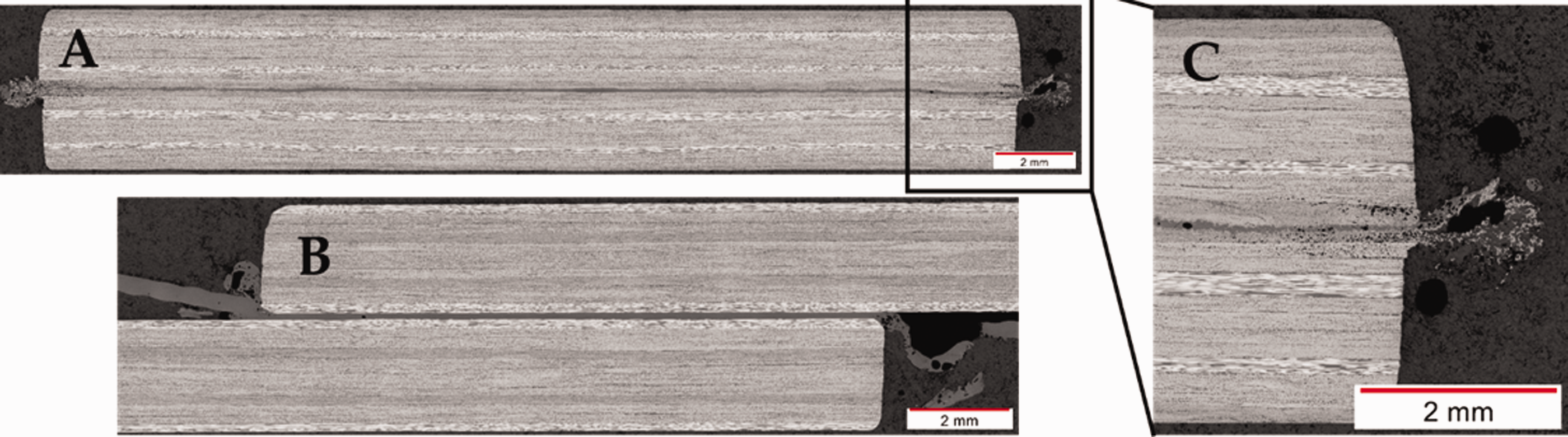
(A) Transversal microscopic cross-section of configuration 90° sample showing little voids and fibre squeeze out in weld line and first ply of adherends. (B) Longitudinal microscopic cross-section of configuration 90° sample showing only polymer squeeze flow. (C) Detailed view on fibre and polymer squeeze out at right side of adherend (as indicated). For all microcuts: Centre of weld line is defect free. Welding parameters are 86.3 µm amplitude, 1000 N weld force and 0.16 mm vertical displacement.
Polymer squeeze flow
The extensive fibre squeeze out and related voids in the longitudinal edges in configuration 0° can be explained by the way the energy director melts. Initial melting occurs at the longitudinal edges of the adherends (Figure 5). Once those edges are completely molten fibres start to flow. This effect is reinforced when the polymer flow starts once the energy director is completely molten. Compared to fabrics, where a 0° ply is always woven and interlocking with a 90° ply, in unidirectional materials each ply contains only one fibre orientation. Additionally, once the matrix is molten the ply can be considered a highly anisotropic homogenized fluid with the following relations for the viscosity in fibre η11 and in transversal direction η12, η13, L/D being the fibre aspect ratio and, η being the polymer viscosity.
29
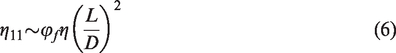

For continuous fibres it becomes apparent that η11 tends to infinity, whereas the transversal viscosities η12 and η13 are matrix dominated and considerably lower. In combination with the applied static force, flow appears transversal to the fibres (η12) towards the longitudinal edges of the adherend for configuration 0°. It has to be noted that the fibres can only flow if the surrounding matrix is completely molten. During the welding process the matrix outside the weld overlap remains solid restricting movement of the fibres. Therefore 0° fibres cannot flow in the longitudinal direction since they are held in place by the solid part of the adherend and the almost infinite viscosity (η11) along the fibres.
From this explanations one would expect considerable fibre squeeze out at the transversal edges of configuration 90° samples. But the polymer does not melt due to the heat transfer into the non-overlapping laminate, therefore delaying the squeeze flow. This explains the non-existence of fibre squeeze out at the transversal edges of configuration 90° adherends (Figure 11(B)).
Narrow energy director
To confirm that the initial melting of the energy director at the longitudinal edges in combination with the through the thickness heating is causing the extensive squeeze out, the width of the energy director is reduced to 17 mm for configuration 0° samples. Hence only 66% of the welding area is covered by the energy director. A sample before welding is shown in Figure 12. Welding parameters are kept equal compared to samples with larger energy directors. Similar to the previous experiments three thermocouples are used to measure the temperatures during the welding process.
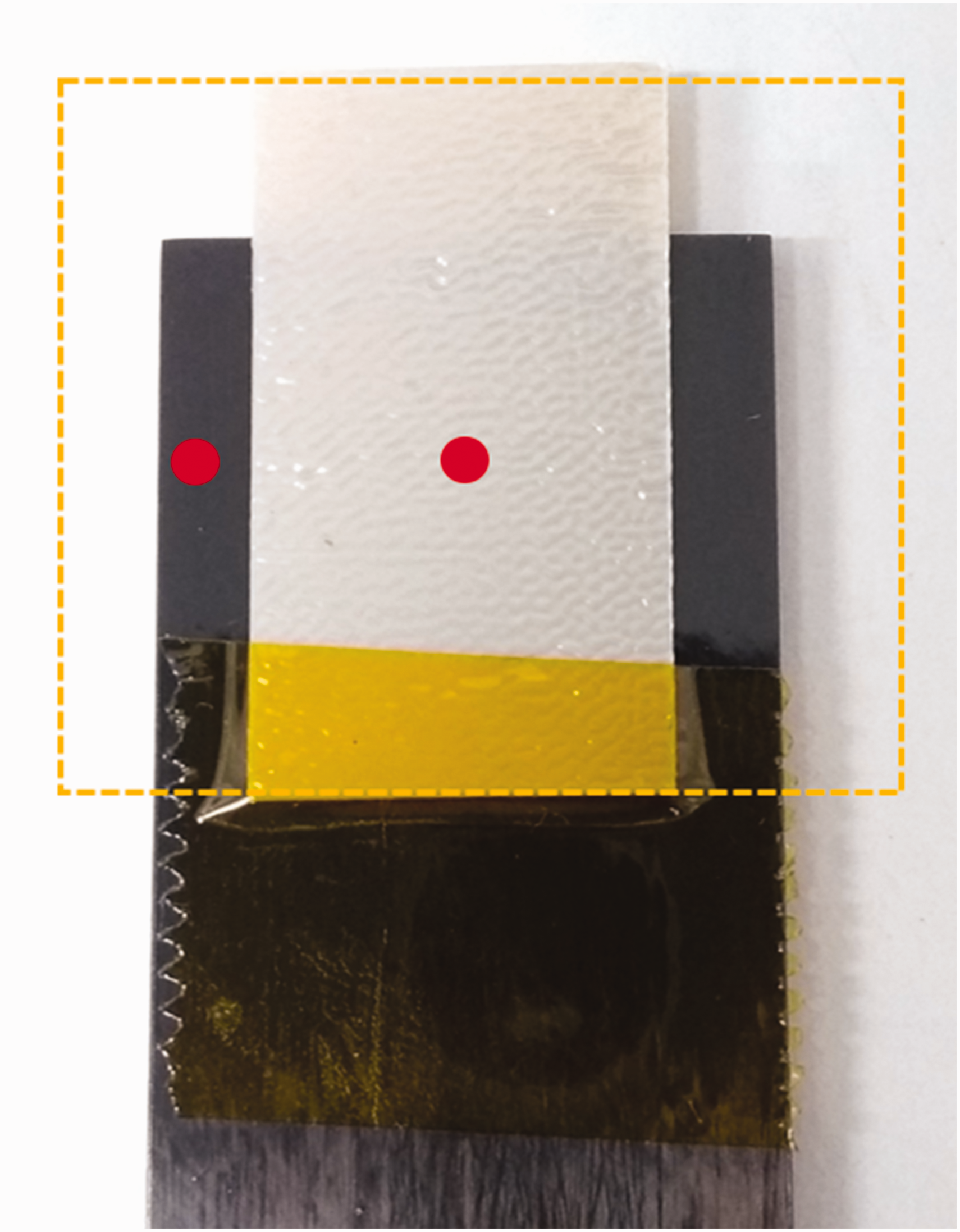
Sample with positioned and taped 30 × 17 mm2 energy director prior to welding. Energy director is taped outside the welding area. Energy director is placed in equal distance to longitudinal edges. Red dots indicate position of thermocouples. Oranges dashed line indicates size of conventional 30 × 30 mm2 energy director.
Figure 13 shows the obtained transversal microscopic cross-section. The edges of the weld line show almost no fibre and polymer squeeze out.
Transversal microscopic cross-section of samples using 30 × 17 mm2 energy director. Welding parameters are 86.3 µm amplitude, 1000 N weld force and 0.16 mm vertical displacement. Minor resin squeeze out can be observed.
Fracture surfaces from samples stopped at different times during the welding process confirm that indeed initial melting of the energy director preferably appears at the longitudinal edges of the energy director. Compared to 30 × 30 mm2 energy directors, where heat transfer at the edges is restricted due to contact to air, the edges of the narrower energy director are surrounded by the adherends leading to more efficient heat transfer. The small air gap between the adherends due to the presence of the energy director can most likely be neglected. But the slippage between the energy director and the adherends is still less restrained at the edges of the energy director, hence leading to higher heating rates and melting at those locations. During the welding process the molten energy director is squeezed towards the longitudinal edges. The surface of the adherends gradually melts while the melt front is progressing, as also seen in literature for other welding configurations.11 The longitudinal edges of the adherends melt last, which prevents the fibre squeeze out.
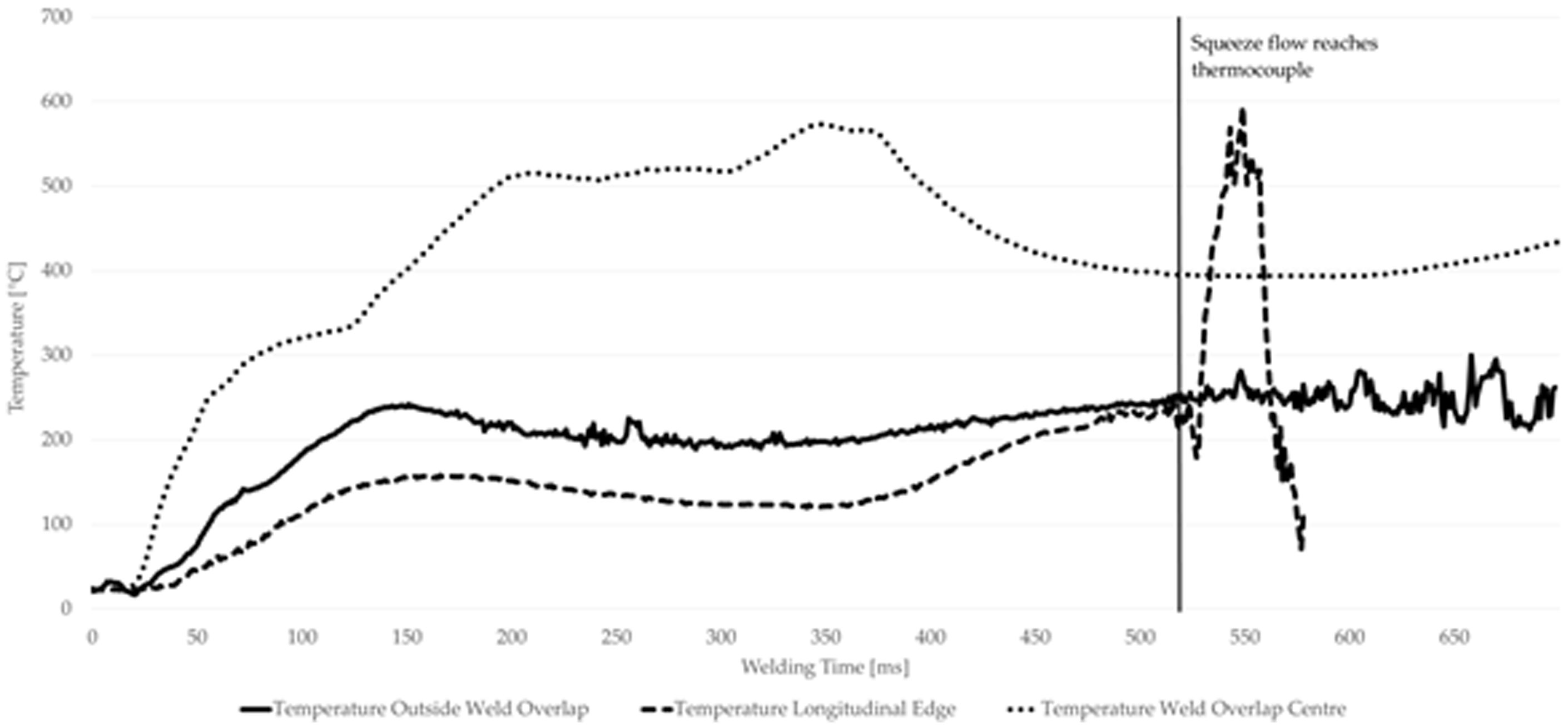
The results of the temperature measurements for the narrower energy director shown in Figure 15 lead to the same conclusion. Compared to the temperature measurements taken from wider energy directors, the centre of the weld overlap shows a faster heating rate. Similarly to the wider energy directors an initial rapid increase to 300 °C can be seen before the heating rate decreases slightly. At 375 ms heating time a temperature drop for the 30 × 17 mm2 energy director can be observed. This drop could be linked to the thermocouple being moved due to the polymer squeeze flow.
The temperature at the longitudinal edge on the other hand remains below 200 °C for most of the process. Towards the end of the process the thermocouple at the longitudinal edge gets in contact with the polymer flow front and shows a rapid temperature increase. The peak temperature of around 600 °C corresponds to what is known from previous trials as maximum temperature inside the weld overlap. Right afterwards the thermocouple shows another rapid decline. Due to the extensive squeeze flow during the process this decline is most likely not linked to an actual decrease in temperature but to failure of the thermocouple. The two wires of the thermocouple are welded at their tips to measure the temperature. Due to the forces induced by the polymer flow the wires could have been torn apart leading to invalid temperatures measurements. This makes it difficult to confirm if temperatures were high enough to achieve proper melting and interdiffusion of the polymer in the first ply of the adherends and the energy director at the longitudinal edges.
Figure 16 compares the temperatures measured at the centre of the weld overlap for a narrow 30 ×17 mm2 energy director and the temperatures measured for a larger 30 × 30 mm2 energy director. The graph shows that for a smaller energy director the centre of the weld overlap heats up similarly to what is known for the longitudinal edges of larger 30 × 30 mm2 energy directors. Although at the beginning of the process the temperature measurements for smaller and larger energy directors at the centre of the weld overlap are very much alike. This can be explained with the positon of the thermocouples in relation to the edges of the energy director. At the beginning of the process the edges of the energy director melt first while the centre of the weld overlap still remains solid. But in case of the 30 × 17 mm2 the distance from the edges to centre is much shorter, 8.5 mm instead of 12.9 mm, compared to the 30 × 30 mm2 energy director. This leads to an earlier melting of the centre of the weld overlap resulting in earlier polymer squeeze flow. If fracture surfaces after 300 ms heating times are compared (Figures 5(C) and 14(C)) significant polymer squeeze flow is visible for the 30 × 17 mm2 energy director while almost no polymer squeeze flow can be seen for the 30 × 30 mm2 energy director. In addition also an earlier increase in temperature leading to a temperature development similar to the temperatures at the longitudinal edges of 30 × 30 mm2 energy directors can be observed for the 30 × 17 mm2 energy director.
Fracture surfaces of samples welded with 150 ms, 250 ms, 300 ms and 400 ms heating time. Orange dashed rectangles indicate initial position of 30 × 17 mm2 energy director prior to welding. Fracture surfaces show initial melting at the edges of the energy director and gradual polymer squeeze flow.
Temperature measurement at the weld overlap centre (dotted line), longitudinal edge (dashed line) and outside the weld overlap (solid line) for sample with 30 × 17 mm2 energy director. Welding performed with 86.3 µm amplitude, 1000 N weld force and 0.16 mm vertical displacement. Vertical line indicates contact of polymer squeeze flow with thermocouple at longitudinal edge.
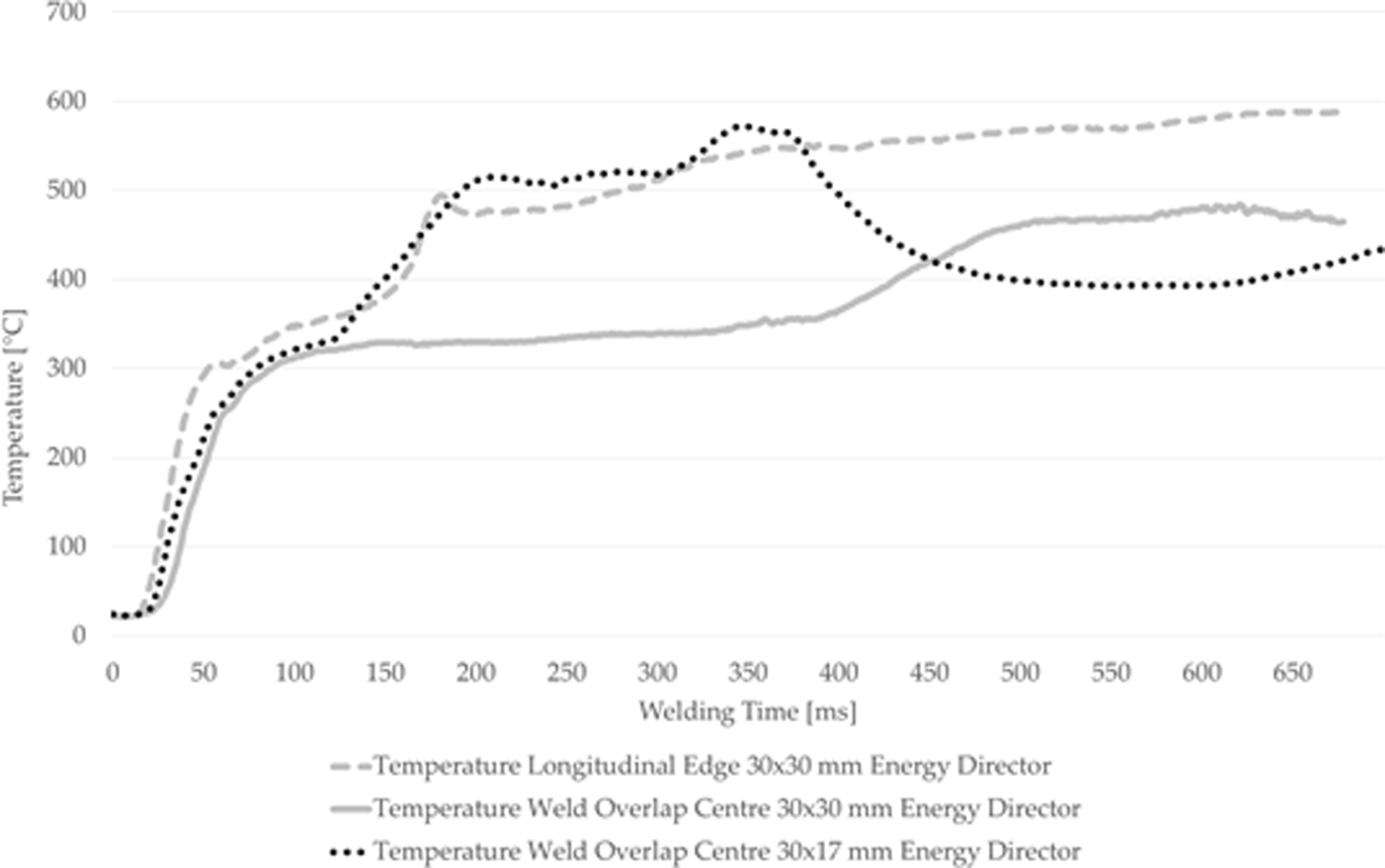
Temperature measurement at the weld overlap centre using a 30x17 mm2 energy director (dotted line) and temperature measurements at longitudinal edge (dashed line) and outside at the centre (solid line) for sample with 30x30 mm2 energy director. Welding performed with 86.3 µm amplitude, 1000 N weld force and 0.16 mm vertical displacement.
Effect of fibre orientation on mechanical performance
Figure 18 shows the lap shear strength of samples welded in both configurations (0° and 90°), with large 30 × 30 mm2 and 30 × 17 mm2 energy directors, at different vertical displacement values. The graph shows that the average lap shear strength for a specific vertical displacement is lower for samples with 30 × 17 mm2 energy director than for samples with 30 × 30 mm2 energy directors. Especially in the early phases of the welding process only little resin squeeze flow takes place which leads to a smaller welded area carrying the load. The fracture surfaces in Figure 17 show that still some unmolten energy director is present at the centre of the weld overlap for a vertical displacement of 0.16 mm (30 × 30 mm2 energy director) and 0.20 mm (30 × 17 mm2 energy director). This usually indicates that the welding process is stopped prematurely and a higher lap shear strength could be achieved with higher vertical displacement, leading also to longer heating times. But as the lap shear strength values in Figure 14 indicate, higher vertical displacements for a 30 × 30 mm2 energy director leads to lower values. This is most likely attributed to an increased fibre squeeze out as less fibres remain in the joint to carry the loads. Considerable fibre squeeze out was already noted for 0.16 mm vertical displacement as shown in Figure 17.
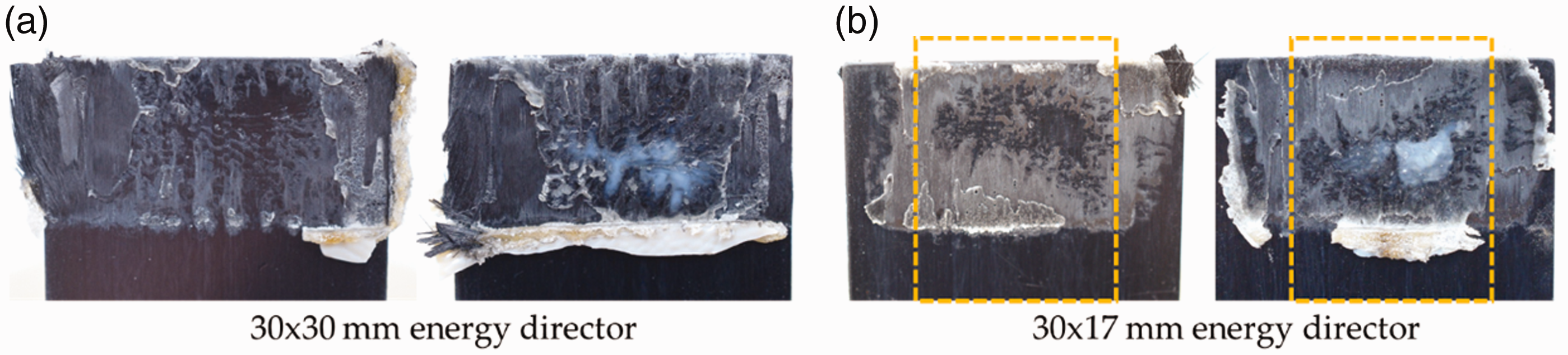
Fracture surfaces of samples welded with 0.16 mm vertical displacement for 30 × 30 mm2 energy director (a) and 0.2 mm vertical displacement for 30 × 17 mm2 energy director (b). Orange dashed rectangle indicates initial position of 30 × 17 mm2 energy director prior to welding.
Figure 17 also shows that unmolten energy director is present for the 30 × 17 mm2 energy director sample. Also some un-welded areas are visible at the edges. Nevertheless, 90% of the maximum lap shear strength compared to samples welded with 30 × 30 mm2 energy director is achieved. If the lap shear strength is corrected for the actual welded area they are even on the same level (37.4 MPa (±2.3) for 30 × 30 mm2 energy director compared to 37.5 MPa (±3.2) for 30 × 17 mm2 energy director). The unmolten energy director in the centre indicates that also for 30 × 17 mm2 energy directors longer heating times or higher vertical displacement should be used. But it has to be noted that the objective of this study was not to identify the optimum energy director size to achieve the highest lap shear strength but to investigate the influence of heat generation and heat transfer on the welding process. Therefore a detailed study to optimize the process further would exceed the scope of this study. However, it can be assumed that an improved welding process using an appropriate combination of energy director size and thickness and vertical displacement can lead to higher lap shear strength results. Compared to the 30 × 30 mm2 energy directors no fibre squeeze out is observed which would diminish the mechanical performance if i.e. higher vertical displacement and consequently longer heating times are applied.
Apart from the size of the energy director also the ply orientation adjacent to the weld line has an impact on the achieved mechanical performance and the fibre squeeze out. Figure 18 shows the lap shear strength values for configuration 0° and 90° using different vertical displacements. The results show an overall reduced lap shear strength for configuration 90°, in accordance with results available in literature.15 The fracture surfaces in Figure 19 show that the failure does not occur in the welding interface but within the 45° and 135° ply for configuration 90°, explaining the lower lap shear strength.
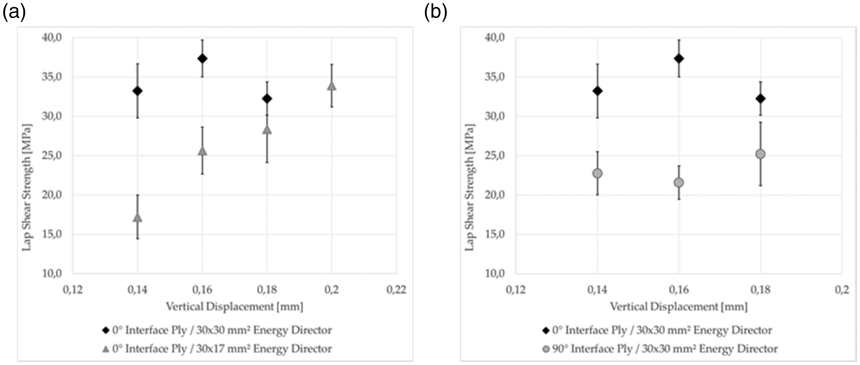
Graphs (a) and (b) show lap shear strength for different vertical displacements. Graph (a) compares lap shear strength of 30 × 30 mm2 energy directors to 30 × 17 mm2 energy directors. 30 × 17 mm2 energy director achieves 90% of max. Lap shear value for higher vertical displacement. Graph (b) compares lap shear strength of configuration 0° and 90° samples with highest lap shear values at 0.16 mm vertical displacement for configuration 0° and almost constant lap shear value for configuration 90°.
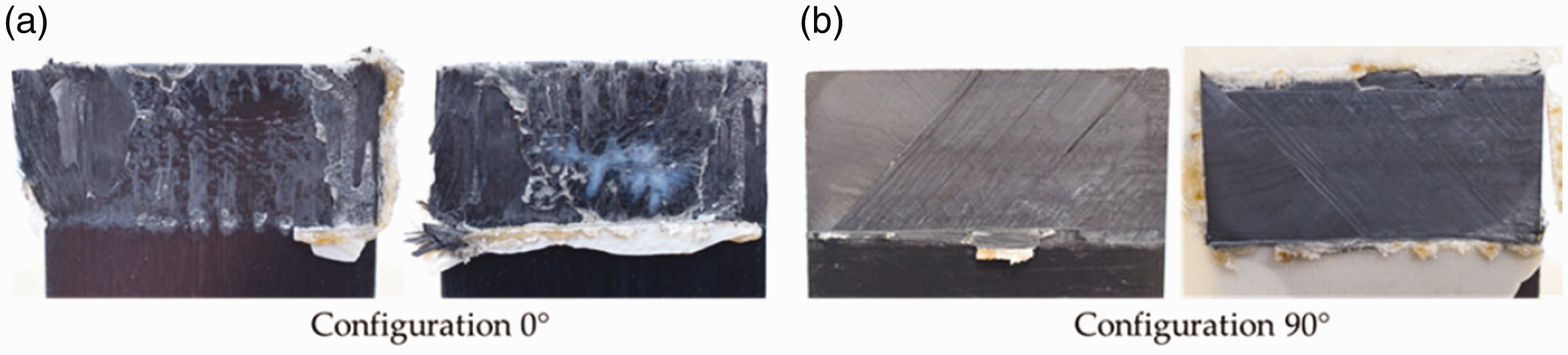
Fracture surfaces of configuration 0° samples (a) and configuration 90° samples (b) welded with 0.16 mm vertical displacement, 86.3 µm and 1000 N weld force. Configuration 0° sample shows severe fibre squeeze out. Configuration 90° shows failure within 45° ply.
The 90° ply in the interface can withstand higher strains. This leads to the effect that most of the loads are carried by the 45° and 135° plies. In comparison to the 0° ply in configuration 0° those plies cannot withstand the same loads leading to earlier failure. Furthermore, the lap shear strength remains constant for different vertical sonotrode displacements applied. This is also linked to the failure mode. While failure occurs in the 45° and 135° ply, the performance of the welding interface plays a minor role and cannot be tested.
Conclusion
This paper investigated how the fibre orientation in the plies adjacent to the weld line influences the ultrasonic welding process of unidirectional carbon fibre PEKK laminates. The effect on edge defects, heat generation and heat transfer was studied. The experimental work was based on samples using 0° and 90° fibre orientations adjacent to the weld line as well as energy directors covering the complete or only part of the intended welding area.
The main conclusions are that the fibre orientation in the plies adjacent to the weld line plays an important role during the welding process and can lead to the appearance of edge defects. Those defects occur mainly if 0° plies are used adjacent to the weld line, while in the case of 90° plies almost no edge defects could be found. Due to less restrained slippage the longitudinal edges of the weld overlap melt first. In combination with the low viscosity of a molten unidirectional ply transversal to the fibres and the polymer squeeze flow fibres are easily squeezed out in the case of configuration 0° samples. 90° plies adjacent to the weld line are less affected as the viscosity along the fibres is almost infinite. Additionally, due to better heat conduction along the fibres (5.94 W/mK) compared to transversal heat conduction (0.36 W/mK) a 90° ply adjacent to the weld line further supports a more uniform heat distribution during the welding process and shorter heating times. The transversal edges of the adherends do not show significant edge defects as the edges remain unmolten for most of the time of the welding process.
The edge defects for 0° plies adjacent to the weld line can be minimised by adjusting the energy director to cover only part of the intended weld area. We showed that an energy director covering 66% of the overlap can prevent the melting of the longitudinal edges. Instead, initial melting appears at the edges of the energy director. After the complete melting of the energy director the subsequent polymer squeeze flow still leads to proper welding of almost the complete weld overlap. The unmolten longitudinal edges prevent the fibre squeeze out. Samples welded with those smaller energy directors achieve the same lap shear strength compared to samples welded with an energy director larger than the overlap. However, even higher lap shear strength could be achieved if an optimised combination of energy director thickness and size and vertical displacement is used.
The fibre orientation adjacent to the weld line also affects the lap shear strength. While samples with 0° plies adjacent to the weld line reach a maximum lap shear strength of 37.4 MPa in average, 90° plies adjacent to the weld line achieve a maximum average lap shear strength of 25.2 MPa. Different failure modes can explain the differences in lap shear strength. For samples with 90° plies adjacent to the weld line failure occurs in the 45° ply which can generally withstand less loads compared to 0° plies.
Footnotes
Declaration of Conflicting Interests
The author(s) declared no potential conflicts of interest with respect to the research, authorship, and/or publication of this article.
Funding
The author(s) disclosed receipt of the following financial support for the research, authorship, and/or publication of this article: The authors would like to thank the Ministerie van Economische Zaken en Klimaat in the Netherlands for supporting this research.