
Abstract
To obtain a larger freedom of design for structural components, a single wire heating element which is capable of welding large and complex shaped surfaces has been developed. The processing window for welds of endless-carbon-fiber-reinforced polyamide 6 (CF-PA6) using the developed heating element is investigated, varying the main process parameters electrical power, electrical energy and joining pressure. The influence of these process parameters on the quality of the welded joints is judged by single and double lap shear tests and by the analysis of micrographs. As a result, recommendations for the processing parameters are derived. The climate conditions of the specimens are varied to analyze the impact of moisture on the shear-transmitting joints whereby an accelerated method for conditioning of PA6 specimens is used. Furthermore, a sensor-free method for monitoring the temperature of the welding process is presented and compared with a classical measuring method.
Introduction
For thermoplastic composites a variety of joining methods exist. In particular, the applicability of welding provides a principal advantage over thermoset composites. Reduced efforts for surface preparation are needed in comparison to adhesive bonds. A special benefit is that the surfaces do not have to be ground, so that welding is a dust-free joining technique. The equipment needed for resistance welding and the process itself are inexpensive. Due to this welding is a key enabler for thermoplastic composites, which becomes more important due to the broader availability of thermoplastic prepregs.
State of the art
The basic principle of resistance welding relies on Joule’s first law, which describes the heating of a conductor while it is passed by a current. The conductor is located between the parts that are supposed to be joined, which then are brought in intimate contact by a joining pressure during the welding process. By applying a current to the conductor, the energy required to melt the joining partners is introduced into the joining zone. After cooling of the melted interface of the parts, a highly load-bearing, substance-to-substance bond is created.
Resistance welding has been studied since the 1990s and there are already very detailed studies of the process and summaries of the state of the art. Particularly noteworthy are the reviews of Stavrov and Bersee and the discussion of the state of the art from Ageorges and Ye, which cover the main aspects of the joining technology.1,2
This study focusses on the conductors used for the generation of heat since they are a key element not only for the process itself but also for the design of parts joined by them.
Over the last decades, different heating elements (HE) were the subject of scientific studies to determine their suitability for the application in fusion bonding of thermoplastic composites. Various criteria were used to evaluate the quality of heating elements. The main criterion for heating elements is the achievable strength of the bonds generated while using them. Furthermore, the robustness of the welding process has to be assessed. The robustness does not only cover the size of the processing window, but also the sensitivity to disturbing influences.
At first, mainly heating elements made of unidirectional layers of carbon fibers were studied due to their excellent compatibility with the joining partners, 3 even though the suitability of metallic heating elements was reported early on. 4 Main problems of carbon fiber heating elements are the fragile nature of the fibers while not being covered by a protective polymer matrix and their anisotropic conductivity. Due to these aspects, electrical contacting of the fibers is complex and usually only an uneven heating of the joining zone occurs.2,5,6 An improvement of the temperature distribution can be achieved by the use of fabrics, but this makes contacting even more difficult.7,8 A much more robust process can be achieved by using fine metallic meshes as a heating element. 6 The influence of the shape of the meshes had been addressed by Dubé et al. 9 Metallic heating elements had shown the potential of reaching a lap shear strength up to the one of compression molded specimens. 6 Newer approaches consider heating elements with carbon nanotubes as a conductor either in form of an additive to polymers or as a directly contacted web.10,11 A geometrically more flexible heating element can be generated by printing conductive silver-ink. 12
While welding carbon fiber reinforced parts, special attention must be paid to the fact that the parts to be joined are themselves electrically conductive. A contact of the heating element thus leads to current leakage, which leads to inhomogeneous temperature distributions in the joining zone.3,7 The intensity of the effect depends strongly on the orientation of layers in contact with the heating element. Strong current leakage and short circuits occur when the layers adjacent to the heating element are oriented in the direction of current flow (0°). If the fibers are oriented perpendicularly to the current flow (90°), the current leakage decreases strongly. 12 To enable welds independent of the fiber orientation, an electrical insulation of the heating element has to be provided. Insulation with thin polymer interlayers had shown insufficient results when the joining pressure is too high. 12 Good results could be achieved by using insulating layers of glass fiber fabrics. 6 Another successful approach is a direct insulation of the heating element by a TiO2 coating. 13
It has been shown that in recent years the development of heating elements for resistance welding enables a robust process for joining highly load-bearing joints. However, the disadvantage of most of the studied heating elements is the limited flexibility in the application at complex joining geometries. The most mature developed conductors made of metal meshes or carbon fibers are of a simple, rectangular geometry and have to be contacted over their entire width, which means that designers have to consider this aspect while developing composite components. The demand for a heating element, which is in particular capable to be used for cylindrical and conical joining surfaces, has been identified in a project for the development of a modular pressure vessel. 14 In general, there seems to be a need for heating elements that can be used in a geometrically flexible way to enable a broader commercial application of resistance welding while designing thermoplastic composite parts.
The aim of this study is to develop a heating element, which is capable to be used for complex shaped, large joining surfaces. Furthermore, it should enable welding with limited access to the joining zone and avoid the risk of current leakage during the joining of carbon fiber reinforced components.
Design approach for a heating element
To enable a flexible adaptation of the design approach for a heating element to complex part geometries, a single wire will be used as conductor. The wire will follow a meandering pattern to cover the desired joining surface of arbitrary shape (Figure 1). Using a single wire, only two single points have to be connected to a power supply, which enables welding with limited access to joining zones. For welds of larger joints, a parallelization of different sections can be used.
Concept for a single-wire heating element.
The wire is fixed between two thin polymer carrier films that are preferably made of the matrix polymer of the adherents. In addition to the fixation, a polymer rich region will be created at the interface of the welding zone and a dry fiber-to-fiber contact of the adherents will be avoided.
To avoid the need of additional insulating glass-fiber interlayers, a direct insulation of the conductor is desired. Therefore, enameled copper wires with a high temperature resistant coating of polyimide are used, whereby a cost saving in comparison to a TiO2 ceramic insulation is achieved. A protection to electrochemical corrosion is also given by this measure. The coating has long term temperature stability of 240°C and a softening temperature above 400°C. 15 A suitability for the welding process for a wide range of polymers can therefore be assumed from a thermal perspective.
It is reported that a high fraction of open area, which is not covered by the conductor, in combination with thin wire diameters show the best mechanical performance.5,9 Due to the use of a single wire without cross-connections a higher fraction of open area can be achieved compared to metal meshes. However, a comparatively thick wire must be used for the heating element in order to ensure reliable contacting.
To assess the suitability of the newly developed heating element, an experimental study on the welding of carbon fiber reinforced PA6 has been carried out.
Methodology of the experimental investigation
Manufacturing of the heating element
For this study, the wire is tied around dowel pins in a meandering pattern with a gap of 1 mm between the wires (Figure 2). The copper wire has a diameter of 0.14 mm with a double layer coating of polyimide, resulting in a total thickness of 0.165 mm. The wire thickness is an important geometric factor of metallic heating elements. When comparing the wire thicknesses of metal meshes studied in the literature with the wire thickness selected in this study, it becomes clear that the wire is considerably thicker than the best performing metal meshes. Dubé et al. recommend wire thicknesses of 0.04 mm, 9 Lang less than 0.1 mm. 5 However, there are differences between the different types of heating elements that must be taken into account. While metal meshes have crossing points where the thickness of the heating element doubles, the single wires have a constant thickness. This relativizes the effective thickness of the single wire heating element. In addition to the wire diameter, the fraction of open area, which is not covered by the wire, is the second important geometrical factor of metallic heating elements. The fraction of open area of the metal mesh recommended by Dubé et al. is 46.7% while the heating element developed in this study has a fraction of open area of 85%. Lang conducted tests to examine the isolated influence of the wire diameter and the fraction of open area. Experiments were carried out with metal meshes of identical wire thickness with different fractions of open area and additional experiments with identical fractions of open area with varying wire thicknesses. It was shown that larger wire diameters have a negative effect on the energy release rate in double cantilever tests, while a larger fraction of open area has a positive effect. When designing the single wire heating element, the conflicting goals have to be solved according to the fact that the wire must be robust enough to minimize the probability of failure during handling while remaining thin enough not to cause too much mechanical distortion in the joining zone. Therefore, a thicker wire than recommended in the literature was used, but for compensation, the fraction of open area was also considerably increased.
Manufacturing details of the tailored single wire heating element.
For contacting, it is necessary to remove the insulation locally at the ends of the coated wire. This can be done either by abrasive brushes or chemically by dipping into potassium hydroxide solution (20%) at a temperature of 90°C for 10 minutes, followed by flushing of the softened coating. The wire is placed between two 0.07 mm thin carrier films made of PA6. To fix the conductor, a short welding process is used in which a welding power of 80 kW/m2 is applied with a joining pressure of 1 N/mm2 over 6 seconds. PTFE-sheets are used to prevent the heating element from sticking to the mold during production. Due to this process, a robust, sheet-like heating element is generated.
Lap shear specimens
The adherents for the mechanical tests are manufactured by compression molding of thermoplastic prepregs. Ten plies of unidirectional, continuous carbon fiber reinforced polyamide 6 (CF-PA6) with a fiber volume fraction of Vf = 49% (BASF, Ultratape B3WC12 UD02) are consolidated to 1.5 mm thick plates. These plates are manufactured in a heated compression mold at a temperature of 235°C with a consolidation pressure of 0.25 N/mm2 over 30 minutes. The pressure is maintained during the cooling phase, which is passive without active cooling. A water-cooled diamond saw is used to cut the plates into the desired shape for the welding process. The welds are performed on sets of a T-shaped and a rectangular plate (Figure 3). This shape allows a single-sided contacting of the heating elements with conventional crocodile clips.
Welding setup for the experimental study. (a) Schematic structure of the welding process and (b) the realization in the welding jig.
Out of each welding set, four single lap shear specimens (LS-specimens) are cut with a diamond saw. The protruding areas of the T-shaped plates are used to place a type-K thermocouple on each side of the joint (Figure 3). Furthermore, a micrograph of each welding set is taken from this area at a sufficient distance to the temperature sensors (Figure 4).
Cutting layout for the lap shear specimens.
The dimension of the lap shear specimens are based on DIN EN 1465, 16 but a modified overlap length is used. As known from Volkersen’s model for single lap joints,17,18 the stress peaks on the edges of the overlap depend on the length of the overlap until a critical length is exceeded. Since the heating element is to be used in a project for the development of a modular pressure vessel design, 14 there is a need for reliable information regarding the achievable joint strengths. Therefore, the overlap length is increased to reduce the effect of the shear stress peak and to improve the comparability with the geometry of large structural joints. To determine the required joint length the critical overlap length can be calculated with the following equation 19 :

Parameters for the calculation of the critical overlap length.
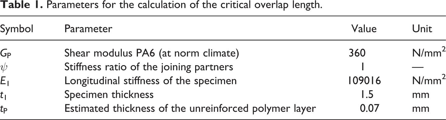
For the calculation of the critical length, the assumption was made that the copper wires can be neglected and the carrier films remain in the joining zone as an unreinforced polymer layer, similar to an adhesive. Preliminary tests had shown that parts of the polymer films are squeezed out of the welding zone and it is furthermore assumed that the polymer partly merges into the joining partners. The remaining layer is approximately 50% of the initial thickness. With these assumptions loverlap is calculated to 19.94 mm (Table 1). To avoid the influence of rising stress peaks in the lap shear tests, the overlap is increased from 12.5 to 20 mm and therefore to a length at which the shear stress peak is independent from the overlap length (Figure 5). In order to be able to evaluate the efficiency of the joining process despite this geometric deviation, additional tests are carried out on compression molded reference specimens and double lap joints.
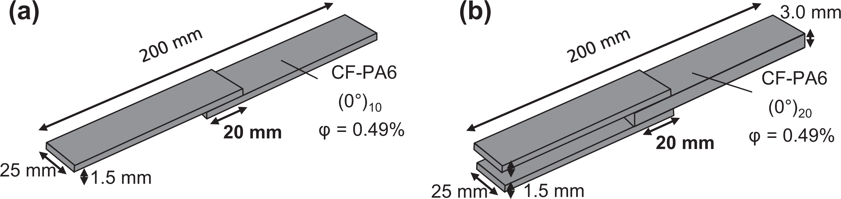
Dimensions of the (a) single and (b) double lap shear specimens with modified overlap length.
Double lap shear specimens
To identify the influence of the bending moment occurring in single lap shear tests, additional double lap shear tests are performed. These tests are also intended to ensure that the increased overlap length does not affect the interpretation of the test results. For the double lap shear tests, the same modified overlap length is used and the thickness of the single sided specimen is doubled to 3.0 mm to avoid coupon failure following ASTM D3528-96 (Figure 5). 20
Compression molded lap shear specimens
To generate a benchmark for the welded specimens, additionally single lap shear specimens are primary molded. Aluminum plates with 1.5 mm thickness are added to the cavity of the compression mold, which was previously used for the production of the test plates, in order to generate the shape of a single lap shear specimen directly in the process. Two of the 0.07 mm thin PA6 carrier films are placed in the overlap in order to achieve the closest possible agreement between the geometry of welded and primary molded specimens (Figure 6). To avoid blurring of the fibers, the pressure of the process had to be reduced to 0.125 N/mm2. Otherwise the same manufacturing parameters were used as for the production of the welding specimens.
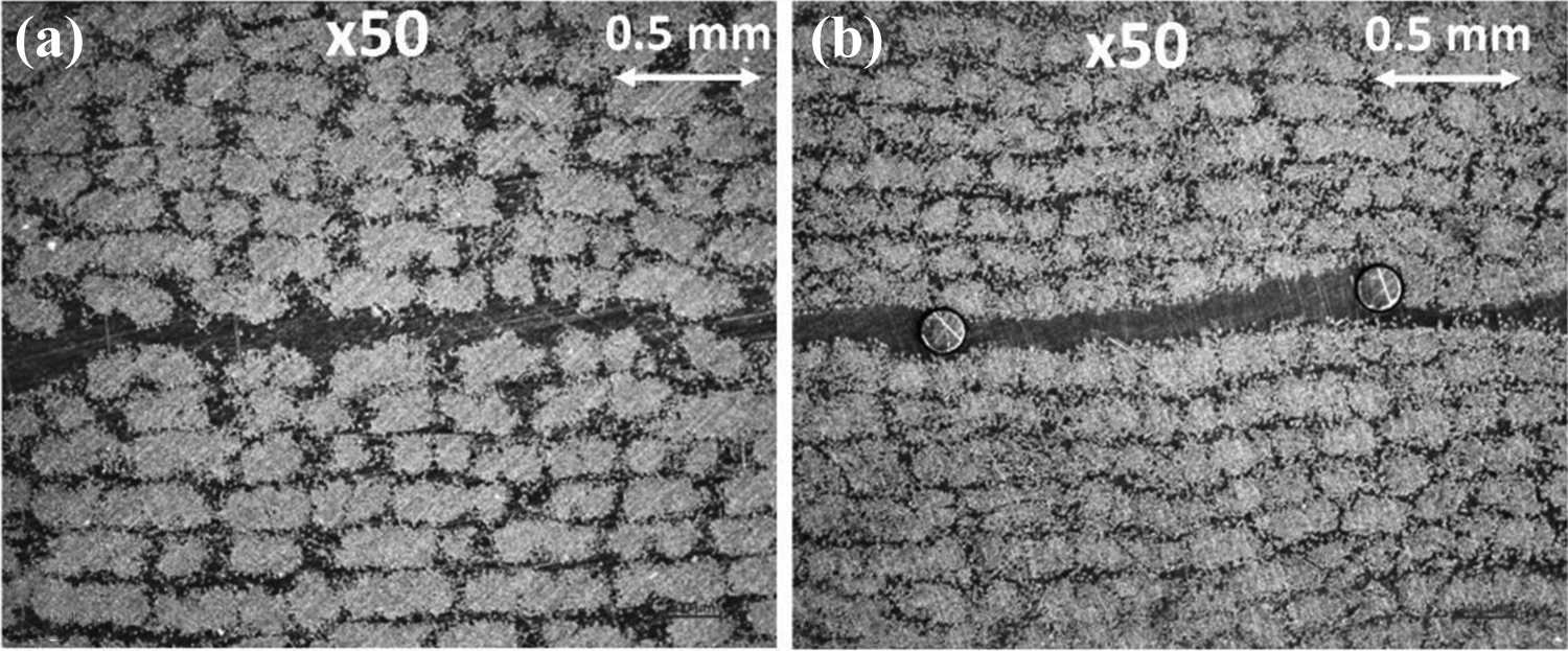
Micrograph-comparison of the cross-section of (a) a compression molded and (b) a welded lap shear specimen (50× magnification).
Welding process
A direct current laboratory power supply (Heiden PSI 8080-340 3U) is used to apply up to 80 V and theoretically up to 320 A. The process is controlled with a LabVIEW program provided by the power supply manufacturer.
The welding process is carried out with constant electrical power. Due to the strongly heat dependent resistance of the copper conductor both the voltage and the current has been adjusted during the welding process. Despite the control of the parameters, the power shows a slight gradient over the welding process. The mean value will be used in the evaluation of the tests (Figure 7). The welding time is determined based on preliminary tests and the desired energy input. In advance of the actual welding process, a current of 1 A is applied over 5 seconds. By this measure, the initial resistance of the welding circuit can be calculated at ambient temperature with Ohm’s law.
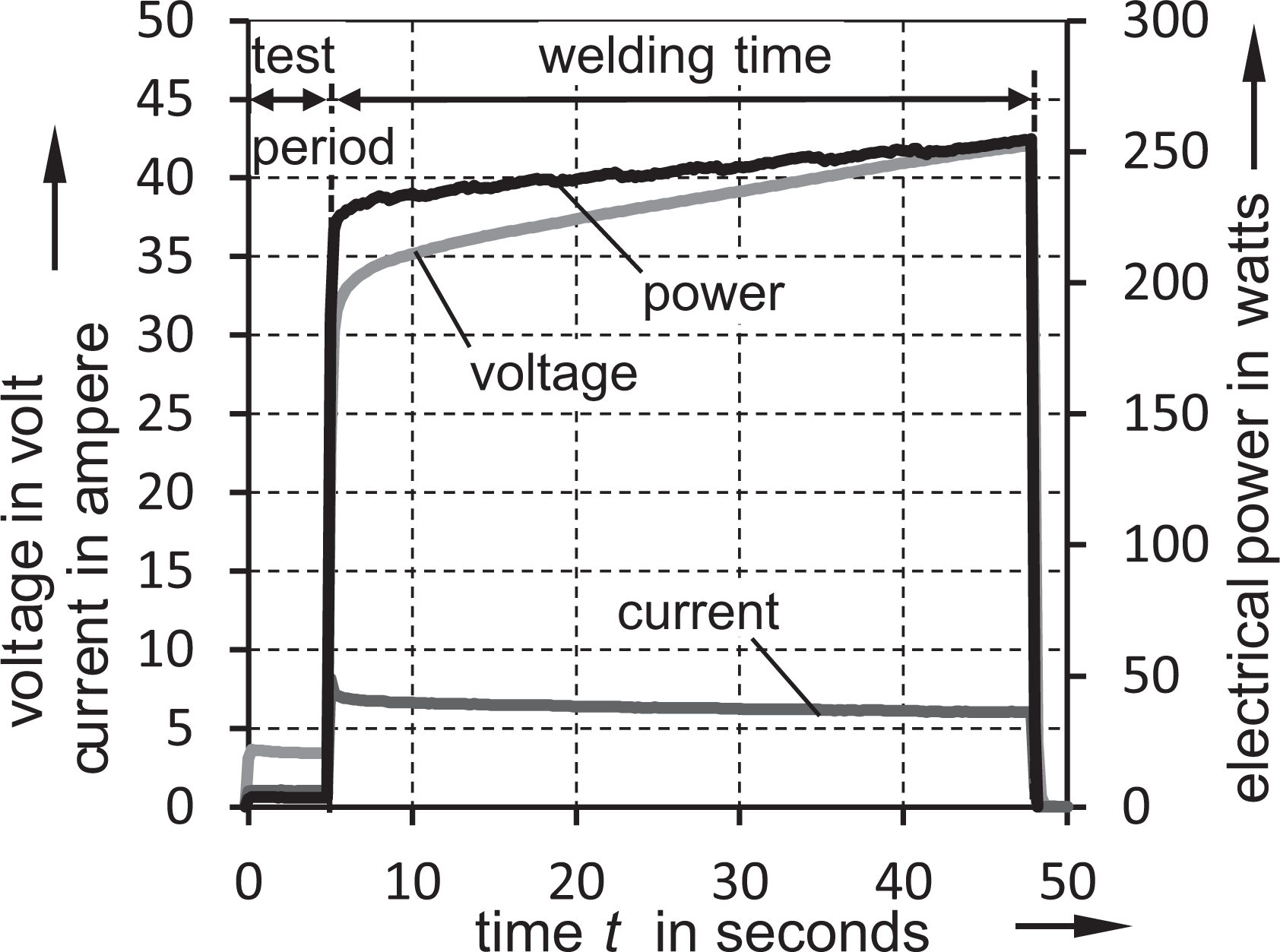
Exemplary electrical parameters of the welding process.
The welding pressure is applied by a hydraulic press. After the initial pressure is applied, no active adjustment is made during the process.
Conditioning of the specimens
Since polyamide 6 is a hydrophilic polymer, it is necessary to consider the moisture content of the specimens during the welding process and the following mechanical tests. It is known that resistance welding of non-dried polyamide 6 specimens leads to a considerable void formation. The pores presumably are formed by the water dissolved in the specimens, when the evaporating temperature of the water is exceeded and they remain locked in the viscous polymer. Substantially lower lap shear strength could be observed with specimens containing these voids. 12 Therefore, specimens and heating elements are dried before the joining process. Following processing guidelines for carbon fiber reinforced thermoplastic tapes the drying takes place in a circulating air oven at 80°C until an equilibrium state is reached. 21
After the welding process, the lap shear specimens are tested at three different moisture contents to enable an estimation of the influence of moisture on the load-bearing capacity of the joints:
- Dried
- Standard climate
- Saturated moisture
The same method is used to dry the specimens as is used to prepare the welds.
According to DIN EN ISO 291, standard climate is defined as the moisture content at the state of equilibrium at an ambient condition of 23°C and 50% relative humidity. 22 Polyamide 6 reaches its equilibrium state at a moisture content of 3 ± 0.4%. 23 Since carbon fibers absorb only a negligible amount of moisture, they can be neglected when determining the content of the specimens. Using the rule of mixture, and considering a fiber mass content of 60%, standard climate is achieved at a moisture content of 1.2 ± 0.16%. An accelerated procedure is used to condition the samples to this moisture content (Figure 8). After an initial drying process, the specimens are kept in a bath of distilled water at 80°C to moisten up to the desired water content. The temperature is thus in the recommended conditioning range of 40-90°C stated by the manufacturer whereby no negative influence of the accelerated procedure on the specimen quality is expected. 23 The water content is determined by measuring the increase of mass with a measuring precision of 0.1 mg. Due to this rapid conditioning, an uneven distribution of the water content will occur along cross-sections of thicker specimens. Therefore, it is necessary to homogenize the moisture distribution subsequently by storing the specimens before testing. By using vacuum-sealed bags for storing, it can be prevented that the moisture diffuses from the specimens. A homogenization period of 14 days has been used. A comparison of four specimens stored for 6 months (M = 36.35 N/mm2; SD = 0.71) and four specimens homogenized for 14 days (M = 37.98 N/mm2; SD = 3.43) welded with the same parameters showed no significant deviation in their lap-shear strength (Welch’s t-test with unequal variances: t(3) = −0.93, p = 0.42> 0.05) using the same welding parameters. Thus, the selected homogenization time seems to be sufficient for the specimens used.
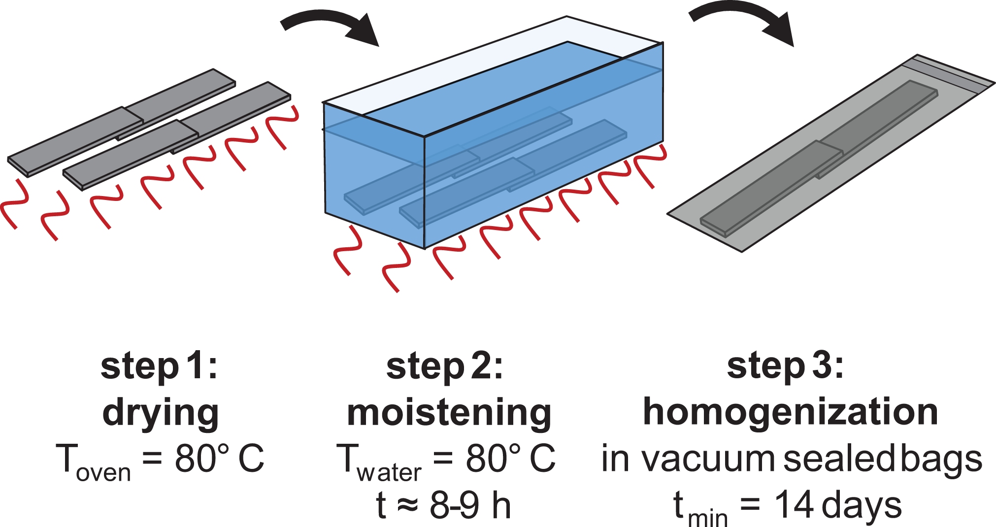
Schematic representation of the accelerated conditioning process.
The specimens that are supposed to be tested at saturation level are kept in a water bath at 80°C until a state of equilibrium is achieved and no further change in weight occurs.
Testing
The lap shear tests are perfomed on a Zwick Roell Z100 testing machine with a crosshead speed of 1 mm/min. To reduce the bending moment in the single lap shear tests, specimen grips are used which compensate the offset of the specimen due to the thickness of the joint.
Temperature monitoring
The welding temperature is measured in two different ways. A direct measurement is realized by two type-K thermocouples placed in the lateral areas of the welding zone, which are not used for the mechanical tests. The mean temperature of both sensors is used in the following. In addition to the thermocouples, the temperature of the heating element is calculated based on the change of resistance of the copper wire in a similar approach to the one proposed by Villegas and Bersee. 24 The temperature dependent resistance of the conductor can be described by the following equation:

wherein, α is the temperature coefficient of resistance of copper, which is stated to be a constant value of 3.93·10−3 K−1 in a temperature range of −100°C to 200°C. 25 The value is still assumed to be constant above 200°C in this study.
It is necessary to isolate the resistance of the copper wire in the electrical circuit to minimize errors due to non-temperature dependent parts of the overall resistance (Figure 9). All connecting lines are presumed to be not temperature dependent due to their considerably larger cable diameters. The same assumption is made for the contact resistances and the power supply. The contact and line resistances RCon were determined in preliminary tests using an Agilent 34410A multimeter. The same multimeter is used prior to each welding process to measure the summed up resistance RM of the connectors and the heating element. In addition, the internal resistance of the laboratory power supply is determined once before the tests are performed. Before the actual welding process, the multimeter is disconnected from the circuit.
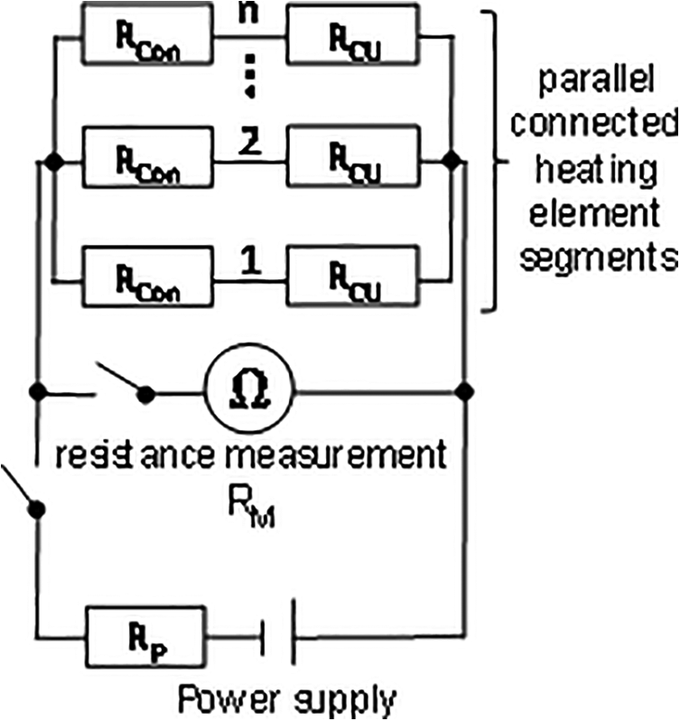
Schematic electrical circuit of the welding setup.
As stated before, the total resistance of the welding setup Rtotal at ambient temperature is determined indirectly in all welding processes using a test current of 1 A (“Welding process” section) and calculating the resistance based on the applied voltage and the source current with Ohm’s law. The same procedure is subsequently used to monitor the complete welding process. It can be described by the following equation:

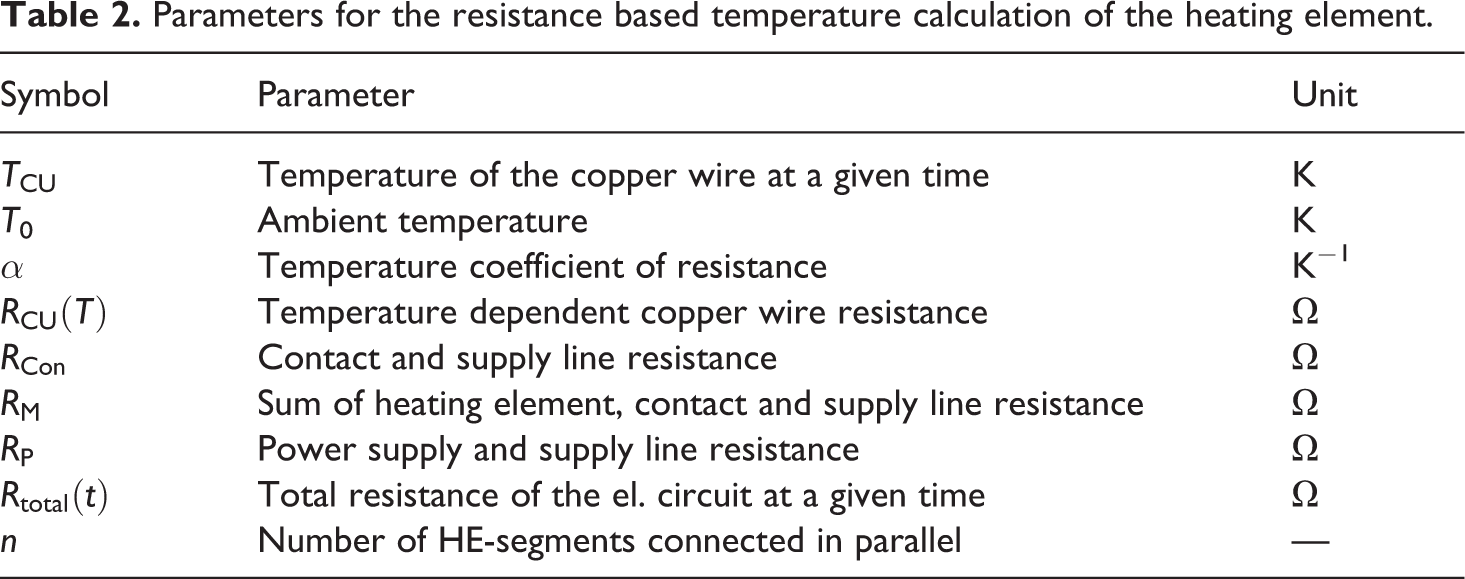
Knowing the total resistance of the circuit, the separated resistances of individual parts and using the equations (2) and (3), the temperature of the heating element can be calculated at a given time in the welding process by the following equation (Table 2):

Parameters for the resistance based temperature calculation of the heating element.
A comparison between both temperature measurements is presented in the “Electrical insulation” section.
Experimental design
The dominant processing parameters for resistance welding are the electrical power and the energy input. 1 Furthermore the welding pressure, applied to bring the parts into contact, is a sensitive parameter. 26 A 32 full factorial design was initially planned to study the influence of the electrical parameters on the strength of the joints, varying the power from 80 to 100 kW/m2 and the energy input from 2.5 to 3.5 MJ/m2. However, the experimental design was extended during the study by two additional data points with a higher energy input at the lower power levels (Figure 10). As the third parameter, the welding pressure is varied in two factor levels from 0.5 to 1.0 N/mm2, resulting in 22 parameter combinations. The limits of the electrical parameters are chosen according to the process window for welding of CF-PA6 with a metal mesh heating element. 12 Since no additional insulating layers have to be used in this study to avoid current losses, slightly lower power and energy values are used. All these tests are performed at standard climate with a moisture content of the specimens of 1.2 ± 0.16%.
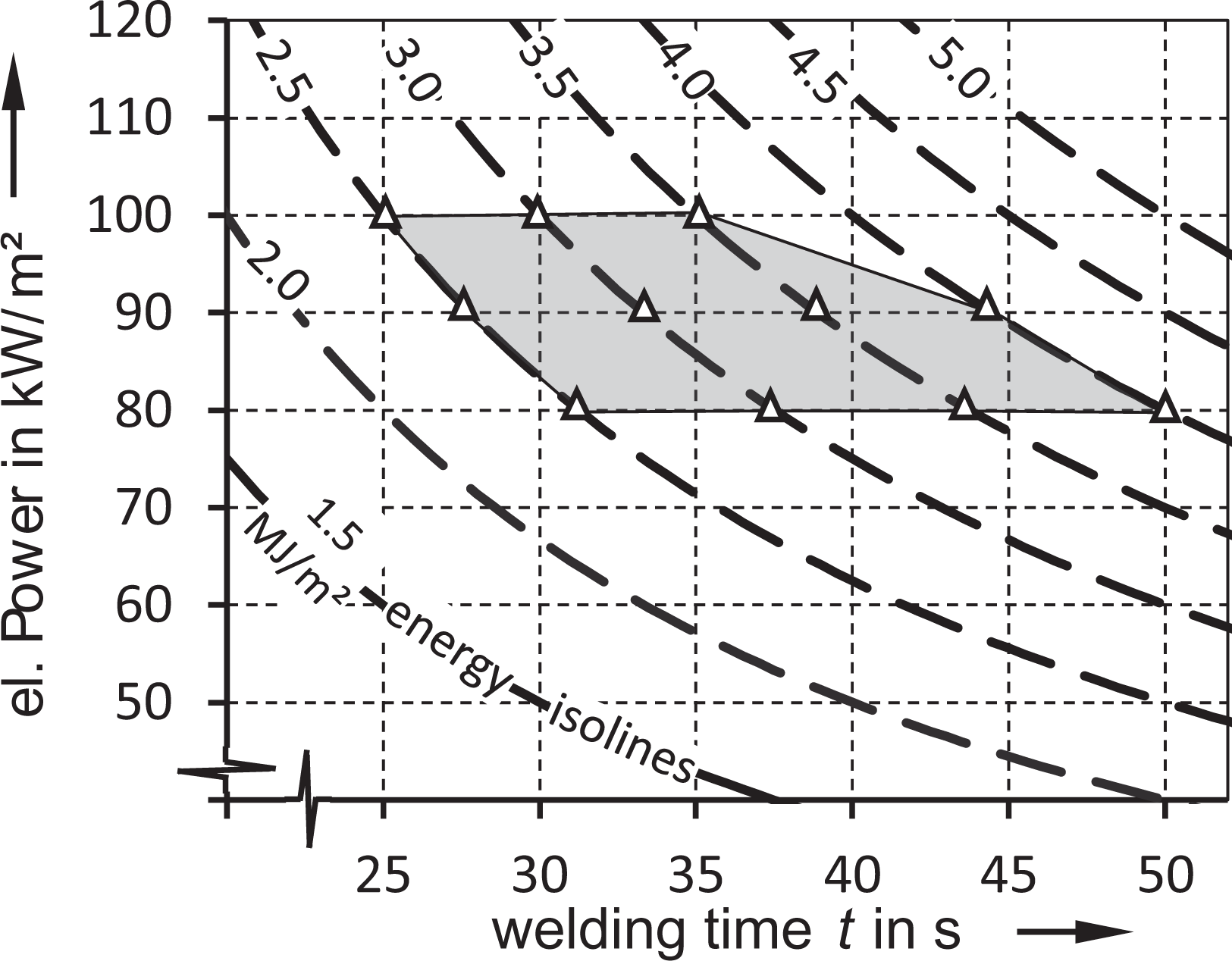
Full factorial design of the electrical parameters for the experimental study.
Further tests are carried out with optimal welding parameters to analyze additional influencing factors on the joint strength. The moisture content of the specimens is varied in three stages from dry over standard climate up to specimens with a saturated moisture content. Moreover, to identify the influence of the sensitive single lap shear tests, additional double lap shear tests are performed.
Results
Electrical insulation
Micrographs show that the polyimide insulation appears intact on visual inspection, even if the welding process exceeds the long-term operating temperature specified by the wire manufacturer (Figure 11). The softening temperature of the insulation, which is specified by the manufacturer as 400°C, can act as a limiting factor for the suitability for welding high performance thermoplastics. In addition, the breakdown voltage of the polyimide insulation is specified by the manufacturer as 12 kV at room temperature and 7 kV at 220°C.
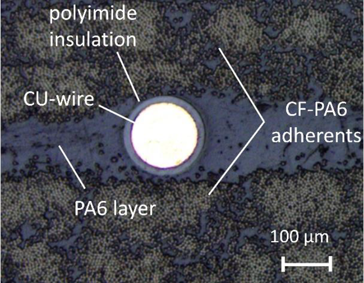
Micrograph of a polyimide coated copper wire used to weld lap shear specimen (P = 80 kW/m2, E = 3.5 MJ/m2) (50× magnification).
The complete study could be carried out without observing short circuits or leakage currents in the documentation of the electrical parameters. In preliminary tests such were observed when the copper wires were stripped beyond the contact points and bare copper wire extended into the specimens. After exceeding the melting temperature, leakage currents could be observed in these cases by distinct irregularities in the current and voltage curves of the welding processes.
Welding temperature
The temperature distribution in the joining zone was analyzed in a preliminary test (Figure 12). For this purpose, a larger joining area of 63 × 150 mm was welded with a heating element consisting of two parallel segments, each with an area of 63 × 75 mm. Five type-K thermocouples had been placed in the welding zone. Three of these sensors were positioned at the border of the weld and two in the middle, whereby one is placed in the transition of the two heating element segments. It can be observed that the edges of the welded area show a lower temperature than the central area but still exceed the melting temperature of the polymer. Although the temperature distribution is not completely homogeneous, the temperatures at comparable positions show only small deviations.
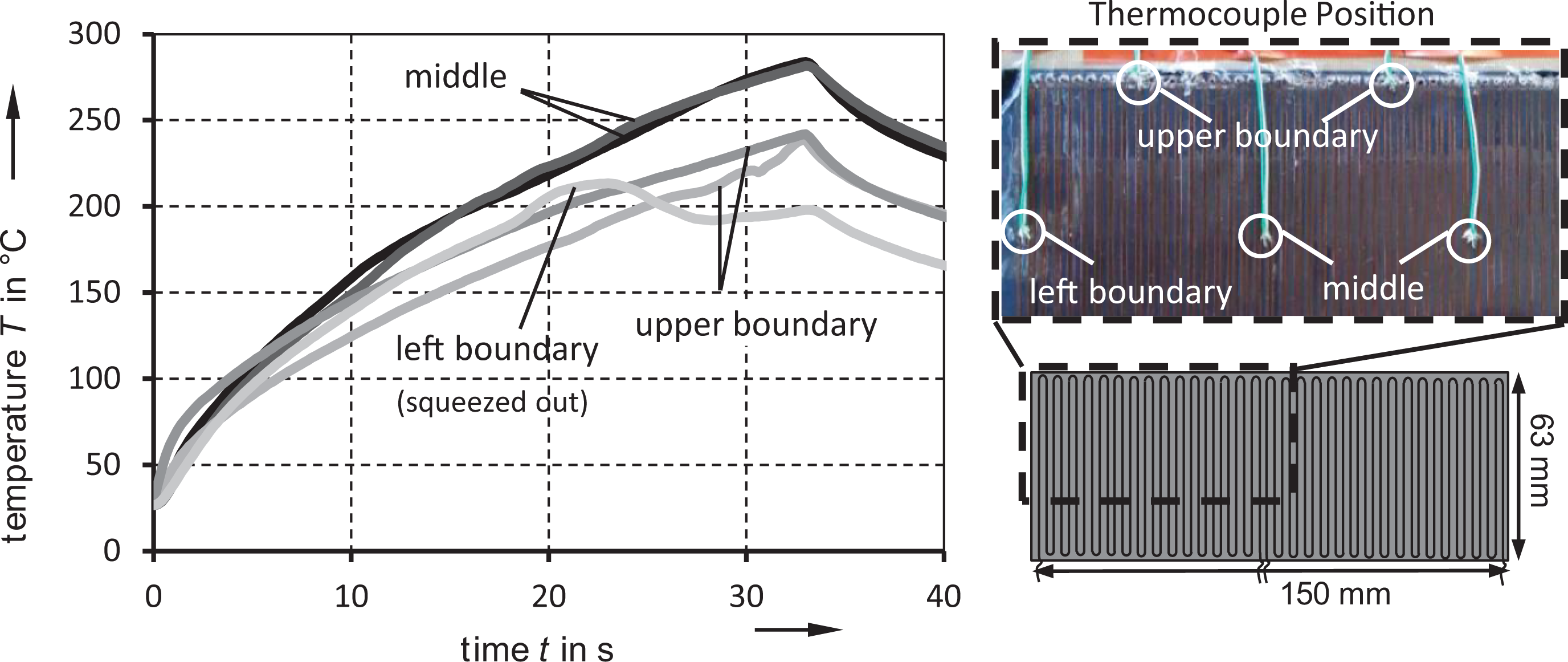
Temperature development measured at five points of a larger welding area with type-K thermocouples. The weld was performed with two heating elements connected in parallel (P = 90 kW/m2, E = 3.0 MJ/m2). The thermocouple at the left boundary was squeezed out when the melting temperature was reached.
The presented method for temperature monitoring by analyzing the change in resistance of the heating element (“Temperature monitoring” section) has to be assessed. A comparison with the results of the type-K thermocouples is carried out (Figure 13). As expected, a discrepancy between the calculated temperature TCu and directly measured TThermocouple occurs. This difference can be explained by assuming that the temperature measured by the thermocouples represents the temperature of the composite averaged over two single points and the TCu the average temperature of the complete heating element. Locally differing temperatures of the heating wire lead to local resistance changes. These wire segments of different resistances are connected in series. The change of the total resistance thus represents the resistance change weighted by the corresponding section length.
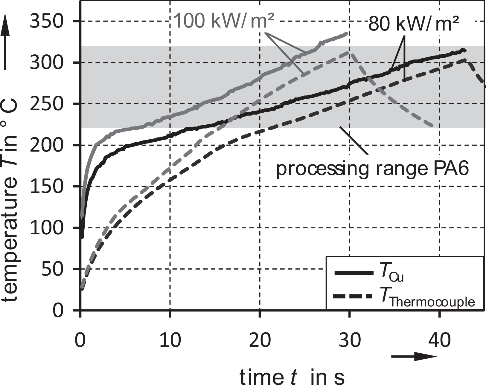
Comparison of the different temperature measurements for two sets of welding parameters.
The temperature curve of the heating element precedes the temperature of the composite as expected from a heat source. The discrepancy decreases after exceeding the melting temperature of the PA6-matrix at 220°C, when the heating wires sink into the composite and the contact surface for heat transport increases. The remaining discrepancy at higher temperatures can be explained by the positioning of the thermocouples in the gap between the copper wires and therefore in a distance to the heating source. The temperature of the specimens and the heating element should converge over the duration of the welding process. In the temperature curves it can be observed that the magnitude of the deviation decreases with rising welding times (respectively higher energy input) especially at lower power levels. The temperature curves therefore appear to be physically plausible, even if no deeper validation of the measuring method could be carried out in this study. When using this indirect temperature measurement, it has to be considered that only a mean temperature of the heating element can be measured without gaining insight into the local temperature distributions. Furthermore larger deviations occur at temperatures below or near the melting temperature of the polymer and while using high power input levels (Figures 13 and 14).
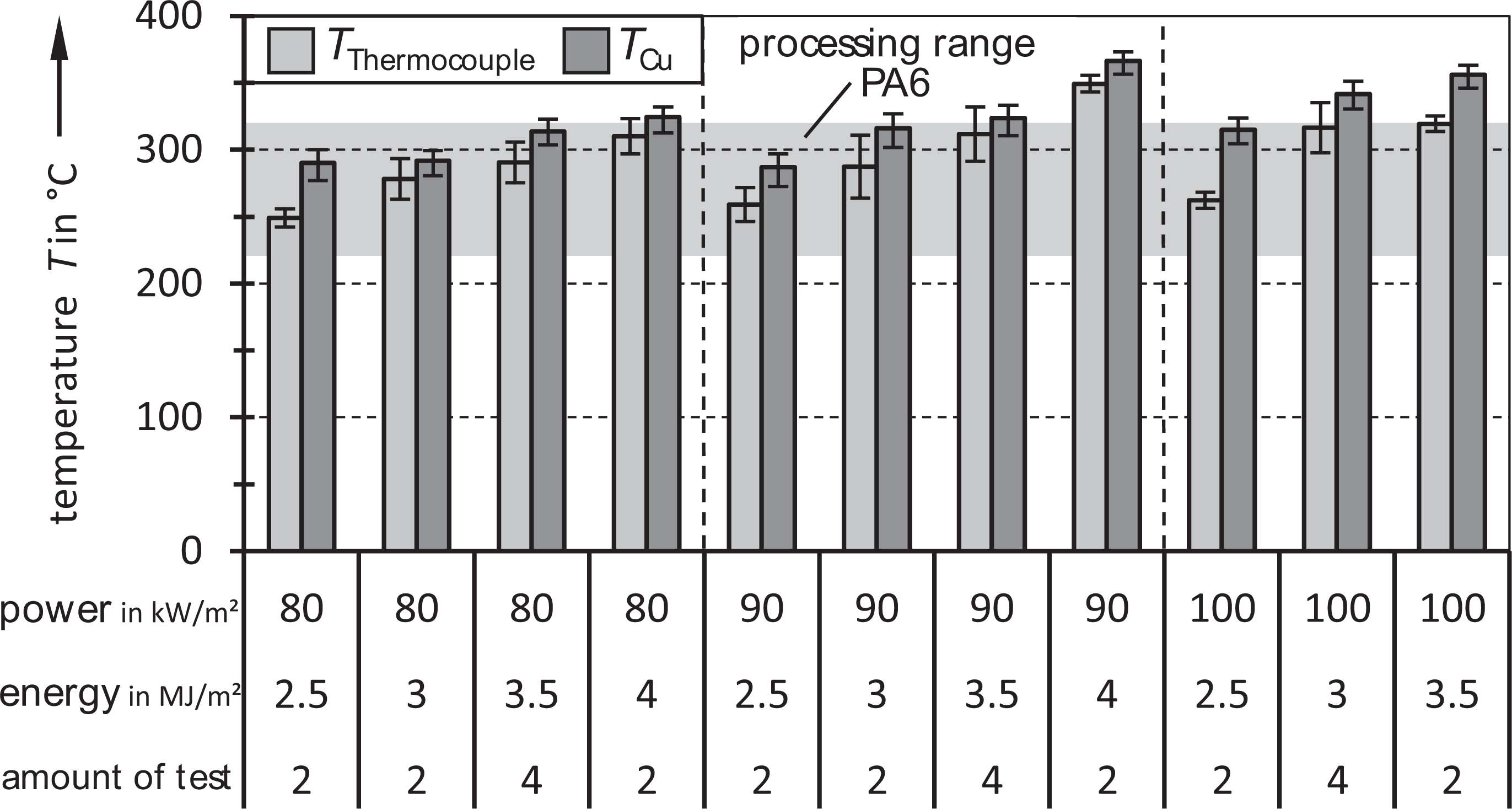
Overview of the maximum welding temperatures resulting from the varied welding parameters.
The analysis of the maximum temperatures reached in the welding process shows that the processing window of the polymer is completely covered by the experimental design (Figure 14).
Welding pressure
The welding pressure is reported to be a sensitive parameter. A minimum pressure is needed to bring the parts into intimate contact. 26 And a too high welding pressure on the other hand, leads to an excessive melt flow in the joining zone, resulting in a dry bonding and fiber slippage. 1 Welding pressures in a range of 0.4 to 1.2 N/mm2 are recommended in the literature.1,8,12 For this study parameter bounds of 0.5 and 1.0 N/mm2 were selected. Since all electrical welding parameters have been tested at both welding pressure levels, a direct analysis of this parameter can be performed (Figure 15). The comparison shows no significant deviation of the lap shear strength in the examined pressure range of 0.5 N/mm2 (M = 38.82 N/mm2; SD = 7.99) and 1.0 N/mm2 (M = 39.29 N/mm2; SD = 8.27) in a t-test with equal variances (t(110) = −0.304, p = 0.76> 0.05).
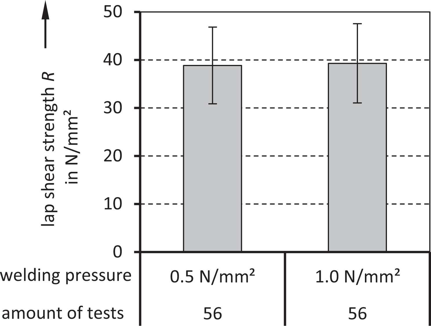
Comparison of all performed single lap shear tests at different welding pressures.
Based on these results, the pressure level is no longer listed separately in the following analyses and the test results are summarized for the corresponding welding parameters.
Lap shear strength and process window
The analysis of the electrical welding parameters shows a clearer picture than the evaluation of the welding pressure (Figure 16). Both parameters show a distinct influence on the lap shear strength. It appears that the energy input has a threshold level, below which only a poor joint quality is achieved, even though the melting temperature of the polymer matrix is exceeded (Figure 14). The magnitude of this threshold, however, depends on the power level. It can be noticed that a higher power level requires a lower energy input. This observation is attributable to heat losses, which are dissipated by heat conduction from the welding zone into the joining partners and also despite thermal insulation into the welding fixture as well as by free convection from the specimen surface. 3 Above the threshold level, the effect size of the energy input decreases. A negative impact on the lap shear strength can be observed when the energy input leads to welding or heating element temperatures above the decomposition temperature of the matrix polymer. This effect is stronger at lower power levels and could relate to the longer welding time required to achieve the higher energy input. A short-term exceeding of the processing temperatures does not seem to have a strong effect on the strength of the joint. The power level has a lower influence on the lap shear strength than the energy input, but it can be observed that a lower power level and therefore a slower heating of the welding zone leads to a higher lap shear strength.
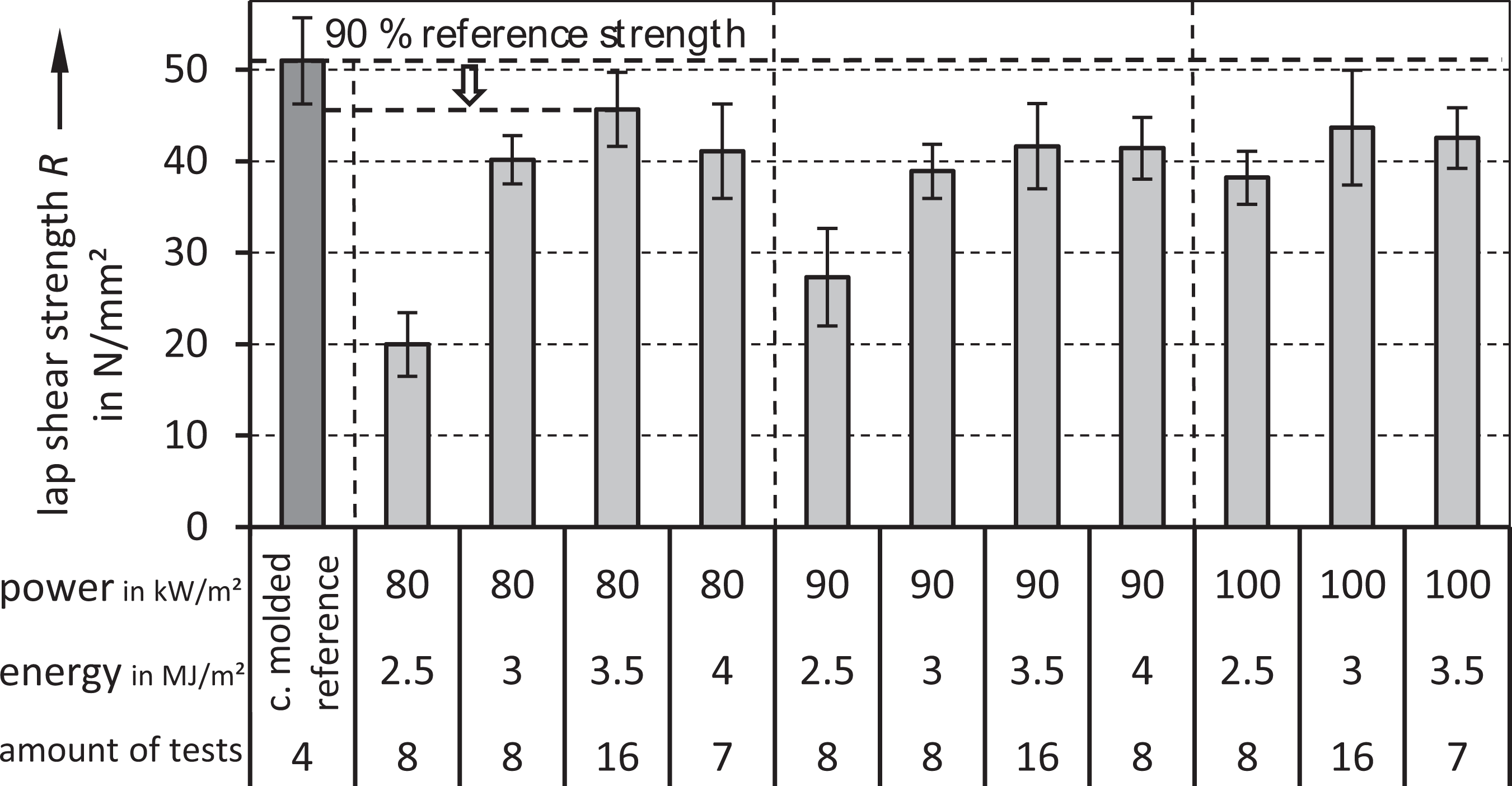
Comparison of all single lap shear tests of the experimental design performed at standard climate (moisture content 1.2 ± 0.16%) including the compression molded reference specimens.
The different welding parameters lead to different fracture patterns of the overlap specimens (Figure 17). In dependence on ISO 10365, the occurring mechanism of failure can be classified in three different categories 27
- Failure mode 1: Adhesive failure
- Failure mode 2: Mixed cohesive and adhesive failure of the heating element
- Failure mode 3: Cohesive failure of the heating element and the first layer of the substrate
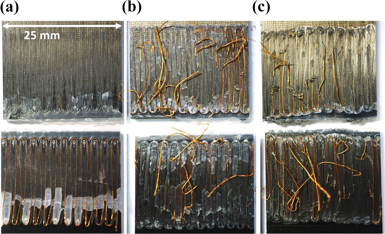
Fracture pattern of lap shear specimens with different welding parameters: (a) 80 kW/m2/2.5 MJ/m2, (b) 80 kW/m2/3.0 MJ/m2, (c) 80 kW/m2/3.5 MJ/m2.
Failure mode 1 results in the lowest joint strengths. This failure mode occurred in 75% of cases for welding parameters of 80 kW/m2/2.5 MJ/m2 and 90 kW/m2/2.5 MJ/m2. It shows that the energy input for these power levels is not sufficient to create a complete substance-to-substance bond. In fracture mode 2 the carrier films are partially still visible in the fracture surface. A good joint quality is achieved when the carrier film has completely bonded to the substrate and is no longer recognizable in the fracture surface. In this case the breakage also occurs in the first layer of the substrate.
From this analysis, recommendations for the process parameters for welding of thin walled parts can be derived (Figure 18). It is proposed to use a power level of 80 kW/m2 and an energy input of 3.5 MJ/m2. However, it should be noted, that the required energy input depends strongly on the thickness of the parts to be joined (see the “Double lap shear tests” section). A recommendation independent of the parts to be joined can be given for the welding temperature. The heating element should reach—at a power level of 80 kW/m2—a temperature above 300°C and below 320°C resulting in welding temperature closely below 300°C. With these parameters, a joining efficiency of 90% can be achieved. The joining efficiency is defined as the ratio of the lap shear strength of welded specimens at optimal parameters to compression molded specimens of the same material and shape.
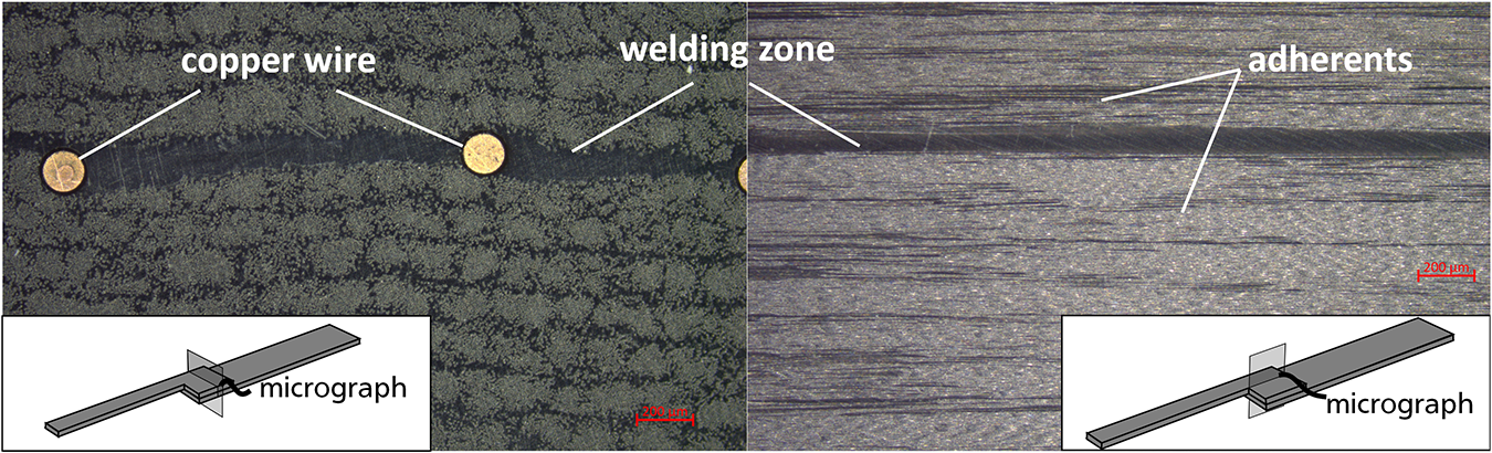
Micrographs of the welding zone of specimen welded with the determined electrical parameters (P = 80 kW/m2, E = 3.5 MJ/m2, p = 0.5 N/mm2).
With these welding parameters, welded joints are created in whose micrographs the PA6 layer of the carrier films is still clearly visible (Figure 19). Lower thicknesses of the unreinforced plastic layer can be achieved with higher joining pressures and a higher energy input, but this leads to lower lap shear strengths in the tests.
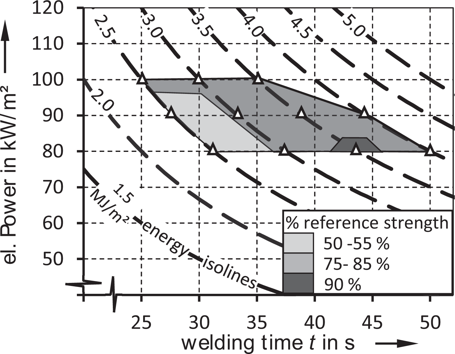
Process window of the single-wire heating element for thin walled CF-PA6 parts.
The other influencing factors considered in the further progress of the study are determined using these welding parameters.
Climate condition
In addition to the welding parameters, the influence of the climate condition needs to be analyzed since a hydrophilic polymer-matrix is used. Its appears, that the mean lap shear strength of specimens conditioned to standard climate decreases only by 8% compared to dry specimens. On the other hand, the strength of specimens moistened to the saturation level is substantially reduced and reaches only 47% of the dry reference value (Figure 20). This can be attributed to two opposing effects. The absorbed water acts as a plasticizer in the PA6 matrix, resulting on the one hand in an increasing elongation at break, but also in a considerable reduction in strength and stiffness. These effects can also be observed at the glass transition temperature which decreases with increasing moisture content. The first effect allows a homogenization of the shear stress distribution along the overlap. Nevertheless, at a certain level the decrease in strength prevails and the strength of the joint decreases.
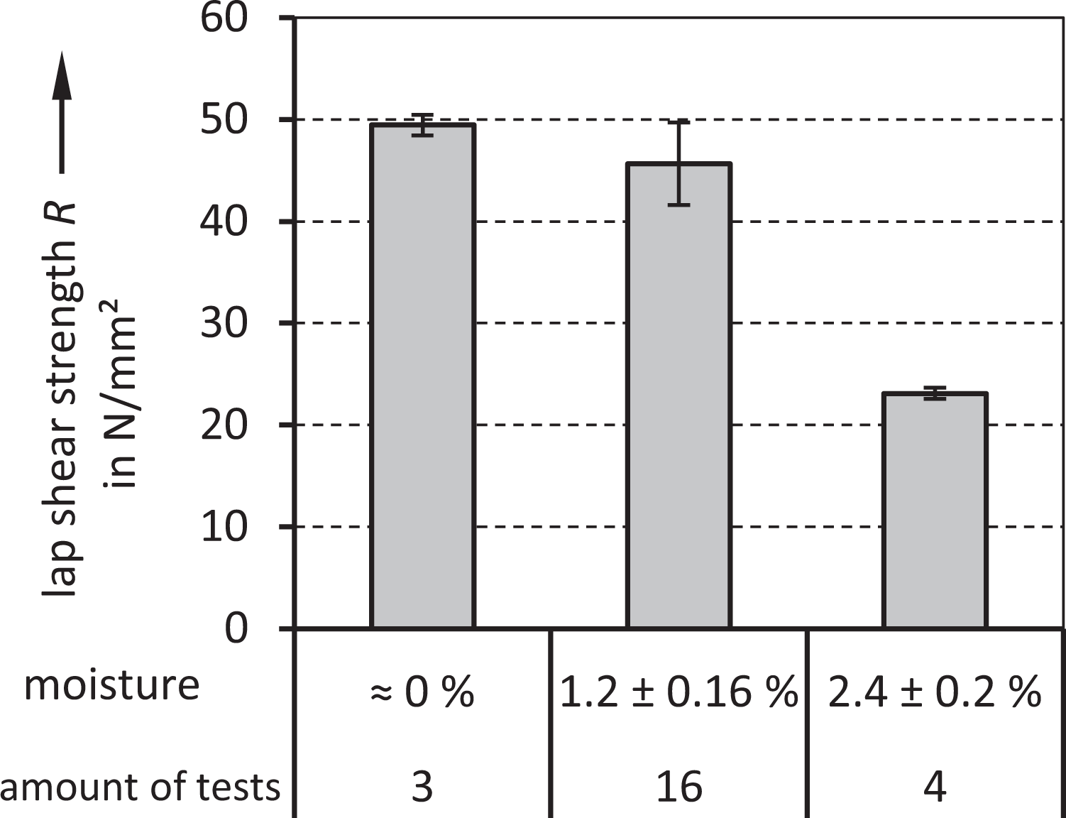
Influence of the moisture content of the specimens on the joint strength.
In order to assess when the strength of the joint starts to decrease more, the dependence of the glass transition temperature on moisture content must be considered. In the literature, glass transition temperatures of 66-78°C are given for dry PA6. For water contents at standard climate (3% unreinforced, 1.2% with a fiber mass content of 60%), Tg is stated at ∼28°C. At saturation moisture, Tg drops to −8 to −12°C.28,29 The reduction of the tensile strength of PA6 in dependence of the moisture content is stated for the grade Ultramid B40 to ∼45% at standard climate and ∼62% at saturated moisture. 30 The manufacturer names a 50% reduction in tensile strength from dry to standard climate for a typical PA6 grade. 31 The stiffness decreases in a comparable magnitude. It can be seen that the reduction in strength of the polymer is not fully reflected in the joint strength. The reduced stiffness of the polymer at higher moisture contents in combination with the increased elongation at break has a positive effect on the strength of the joint. It allows a homogenization of the shear stress distribution and leads to a better material utilization in the joining area. It is reasonable to assume that the sharp reduction in joint strength first occurs when the glass transition temperature is exceeded, which was not the case for the specimens conditioned to standard climate.
Double lap shear tests
Lap shear tests on single lap joints are simple and have the advantage of easy specimen production. However, the test does not allow determining the actual shear strength of the joint due to its inhomogeneous shear-stress distribution. Furthermore, the test setup is very sensitive to geometric deviations. In order to validate whether the geometric deviations made in this study were permissible, additional tests are carried out on double lap shear specimens. By this measure the bending moment, which occurs in single lap shear tests and superimposes additional tensile stresses in the thickness direction on the shear stress, gets counterbalanced. The magnitude of the bending moment depends on the length of the overlap, the thickness and stiffness of the specimen. If the influence of the moment can be estimated, a statement can be made about how important the geometric influence of the single overlap joints is. The tests show that the mean strength of double lap joints only rises by 4% in comparison to single lap joints (Figure 21). The influence of geometry therefore seems to be only of secondary importance and the single lap shear tests with adjusted overlap length are sufficient to judge the suitability of the process and determine the process window.
Comparison of double lap shear strength tests with the single lap shear reference value.
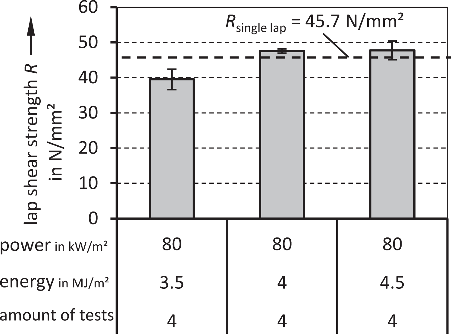
The transfer of the welding parameters from single lap joints led to a suboptimal result while welding the double lap joints. This can be explained by the greater thermal mass of the thicker double lap specimen. An increased energy input is needed to heat up the joining zone to the desired temperature (Figure 22).
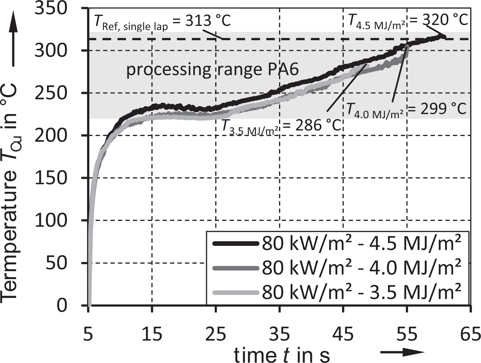
Temperature development of the heating element during the welding of double lap joints with different energy levels.
After increasing the energy input a high quality joint could be generated. It is therefore recommended to check the achieved welding temperatures and to adjust the energy input according to the process recommendations (“Lap shear strength and process window” section).
Conclusion and outlook
A new design for a heating element for resistant welding of thermoplastic composites has been presented which can be adapted to complex joining zones and includes direct insulation to avoid current leakage. An extensive experimental study was conducted to determine the process window and to estimate the influence of climatic conditions on the joint strength with single lap shear test. To validate the test setup additional double lap shear test have been carried out. The tests showed that a joint efficiency of up to 90% can be achieved with this heating element. In addition, a sensor-free method for temperature monitoring of the process has been presented, which enables a cost-efficient process monitoring.
Future work on this heating element should be the optimization of the wire-layout to homogenize the temperature distribution in the welding zone. This could be carried out in a numerical study followed by an experimental validation. Furthermore, long-term-loads and the creep behavior of welds with this heating element should be analyzed. In addition, the fatigue strength of the joint has to be determined and finally, the transfer to the component level can be made.
Footnotes
Acknowledgements
The authors would like to thank the DFG for their financial support, the BASF SE (Ludwigshafen, Germany) for providing the CF-PA6 tapes and MF-Folien GmbH (Kempten, Germany) for providing the PA6 films.
Funding
The author(s) disclosed receipt of the following financial support for the research, authorship, and/or publication of this article: This work was supported by the Deutsche Forschungsgemeinschaft (DFG, German Research Foundation), Projektnummer 391936435.