
Abstract
An experimental investigation of resistance welding of thermoplastic composite double lap shear (DLS) joints is presented. DLS specimens consisting of unidirectional carbon fibre/polyetheretherketone (CF/PEEK), carbon fibre/polyetherketoneketone (CF/PEKK), carbon fibre/polyetherimide (CF/PEI) and 8-harness satin weave fabric glass fibre/polyetherimide (GF/PEI) composites were resistance welded using a stainless steel mesh heating element. The welded specimens were tested under static and fatigue loadings, and the quality of the welds was examined using optical and scanning electron microscopy. Weld strengths of 53, 49, 45 and 34 MPa were obtained for CF/PEEK, CF/PEKK, CF/PEI and GF/PEI DLS joints, respectively. Indefinite fatigue lives were obtained between 20 and 30% of the ultimate static failure loads of the joints. Performances of the resistance-welded DLS and single lap shear (SLS) joints were compared. It was shown that the effect of joint geometry, that is, DLS versus SLS, on the mechanical performance of the resistance-welded joints is minimal, indicating a good resistance of welded joints to peel stresses.
Introduction
Several welding methods are available to join the parts of thermoplastic composites. These methods can be classified into three categories based on the heat generation mechanism at the weld interface: thermal, friction and electromagnetic welding. 1 One of the most promising methods, resistance welding, was selected by Fokker Aerostructures (the Netherlands) to assemble the skin and ribs of the leading edges of the wings of the Airbus A380 and A340-600 airplanes. 2 This electromagnetic welding method was shown to be fast and simple and provide consistent weld strength and quality. In resistance welding (Figure 1), the heat is provided by an electrically resistive implant, called heating element, which is placed between the parts to be joined. When electrical current passes through the heating element, heat is generated by the Joule heating effect. The temperature increases at the interface between the two parts, and the polymer surrounding the heating element softens (amorphous polymers) or melts (semi-crystalline polymers). When a predetermined welding temperature is reached, the current is stopped and the joint is allowed to cool down while the pressure is maintained, until it solidifies and forms a weld. The heating element remains trapped in the joint, allowing potential repair or reprocessing of the weld by applying electrical current again. 3
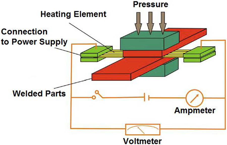
Resistance welding principle.
Several experimental investigations were conducted on resistance welding of thermoplastic composites. These investigations mostly focused on optimization of welding processing parameters, such as heating element type (e.g. carbon fibre heating element vs. stainless steel mesh heating element), processing temperature and pressure and ways of applying current to the heating element. These parameters were generally optimized using single lap shear (SLS) specimens. Some studies also focused on double cantilever beam specimens or skin/stringer configurations. 4–9 A series of models were also developed that provided a better understanding of the effects of resistive welding parameters on the weld quality and strength. Among the main conclusions of those studies, stainless steel mesh heating elements were shown to provide better consistency and superior mechanical performance than carbon fibre heating elements and ranges of welding temperatures and pressures were defined for a few high-performance polymers. 6–7,10,11 Ageorges et al. 6 showed the effect of the welding pressure on weld quality. Pressures varying between 0.2 and 1.6 MPa were shown to lead to acceptable lap shear strength and an optimum pressure of 0.5 MPa was reported for carbon fibre/polyetherimide (CF/PEI) material. Talbot et al. 11 showed how the clamping distance, which is the distance between the edge of the joint and the connector to the power supply, affects the temperature distribution over the weld area. Optimizing this parameter can improve the heat distribution and provide a more uniform heating for SLS joints. The stainless steel mesh heating element size (wire diameter and open gap width) was optimized for better mechanical performance. 12,13 Failure modes of SLS and typical aerospace skin/stringer joints were also reported. 8,9
The effect of fatigue loading on resistance-welded joints has not been studied extensively. A few studies used SLS specimens to compare the fatigue behaviours of amorphous and semi-crystalline thermoplastic composites. 14,15 In another study, the failure modes and crack propagation in a skin/stringer joint had been described. 16 An infinite fatigue life was obtained when cycling the specimens from 25 to 30% of their ultimate static strength under a load ratio R = 0.1. This performance is similar to that of adhesively bonded joints. However, when compared in terms of absolute fatigue stress, the welded joints show an advantage over the adhesively bonded joints, since their static strength is higher. More work related to the fatigue behaviour of resistance-welded joints, both experimental and modelling, is needed.
Since joints are often considered as a structural design criteria, numerous studies were conducted on adhesive bonding of composite materials. The previous studies have shown that joint configurations inducing load path eccentricity and out-of-plane stresses should be minimized when designing a composite structure because of the reduced failure loads associated with such configurations. 17–19 Although the SLS geometry is known to produce such out-of-plane stresses, it is still often used to characterize adhesively bonded joints because of the simplicity of manufacturing and testing the specimens. However, in order to reduce the out-of-plane stresses, other joints’ geometries were also developed. In particular, the double lap shear (DLS) test was shown to reduce significantly the out-of-plane stresses. 20
The objective of the present article is to characterize resistance-welded DLS specimens for various material systems, that is, amorphous and semi-crystalline thermoplastic polymers reinforced by either carbon or glass fibres. A second objective is to describe the mechanical performance and failure modes of resistance-welded thermoplastic composites under fatigue loading, for which only little information is available in the literature. To achieve those objectives, DLS specimens were resistance welded using stainless steel mesh heating elements and were tested under static and fatigue loading conditions. Failure modes and weld quality were assessed using optical and scanning electron microscopy (SEM), and the mechanical performances and failure modes of DLS and SLS specimens were compared.
Experimental
Materials
The adherends consisted of 16 plies of unidirectional carbon fibre/polyetheretherketone (CF/PEEK[0]16), 16 plies of unidirectional carbon fibre/polyetherketoneketone (CF/PEKK[0]16), 16 plies of unidirectional CF/PEI (CF/PEI[0]16) and 8 plies of 8-harness satin weave glass fibre fabric polyetherimide (GF/PEI [0]8). PEEK and PEKK are semi-crystalline polymers with melting temperatures of 343 and 310°C, respectively, and PEI is an amorphous polymer with a glass transition temperature of 218°C. The CF/PEEK, CF/PEKK and CF/PEI laminates were 2.2 mm thick and were provided by Cytec Engineered Materials Inc. (California, USA). The GF/PEI laminates were 2.0 mm thick and were provided by Ten Cate Advanced Composites (California, USA). Adherends were cut off from the laminates using a water-cooled diamond saw with a dimension of 101.6 × 25.4 mm2.
The heating element used for the resistance welding operation was a plain weave stainless steel mesh with a wire diameter of 0.040 mm, an open gap width of 0.089 mm and a thickness of 0.080 mm. 13 The ends of the mesh were clamped between two copper electrodes in order to make connection with the power supply (Figure 1). All meshes were cleaned with acetone prior to resistance welding. In order to have a resin-rich region at the weld interface and fill the gaps between the wires of the heating element, neat polymer films of the same polymer type as the adherends were placed on each side of the heating element.
Resistance welding
The DLS specimens were manufactured using two welding operations that were conducted sequentially. In the first operation, two laminates were welded in an SLS configuration (Figure 2). Power was supplied to the heating element using a Xantrex XPR (British Columbia, Canada) (40 A, 150 V alternating current/direct current). Ramped voltage method was used with an initial voltage of 2.0 V and a ramp up rate of 10.0 V/min. When the weld interface reached a welding temperature of 440°C (CF/PEEK), 410°C (CF/PEKK), 390°C (CF/PEI) or 345°C (GF/PEI), the current was stopped and the weld interface was allowed to cool. A constant pressure of 1 MPa (CF/PEEK, CF/PEKK and CF/PEI) and 60 kPa (GF/PEI) was applied during the process. The selected parameters are based on previous studies, demonstrating that those temperatures and pressures lead to good weld quality. 6,11,13 In particular, it was shown by Talbot et al. 11 that the parameters that were used led to a complete weld avoiding polymer degradation. Once the first weld was done, the specimen was flipped over and was resistance welded again with another laminate (Figure 2). Same welding temperatures, pressures and power input were used for this second weld. The final specimen geometry was a DLS joint.
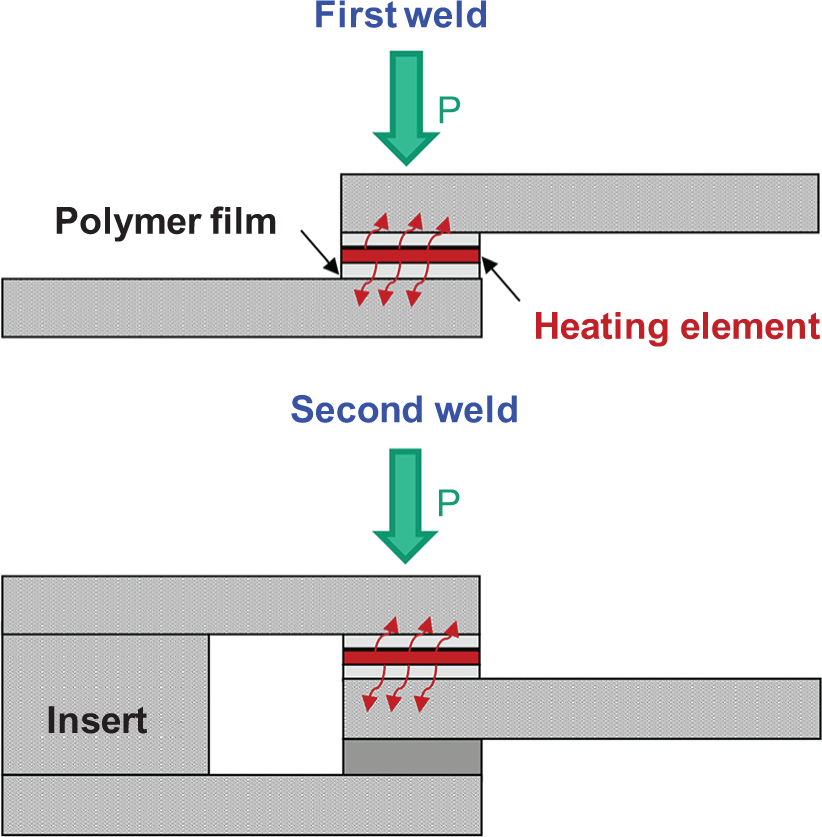
Schematic representation of resistance welding operations for double lap shear joints.
Mechanical testing and characterization methods
The mechanical properties of the joints were determined in accordance with the ASTM D3528 standard test method.
20
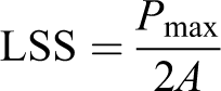
The samples were 190.5 mm long and 25.4 mm wide, with two overlap surfaces, each 12.7 mm long. They were clamped at each end between the hydraulic grips of an MTS 100 kN servo-hydraulic machine, with a clamped length of 25.4 mm at each end, as shown in Figure 3. A tab made of the same material and same thickness as the laminates of the specimen to be tested was inserted between the two outer adherends in order to avoid bending from the clamping (Figure 3). The free length between the grips was 139.7 mm. The cross head speed was 1.3 mm/min, and the samples were tested under standard conditions at a room temperature of 23°C and a relative humidity of 50%. A minimum of five replicated samples were tested for each material. Apparent lap shear strength (LSS) was calculated using the following equation
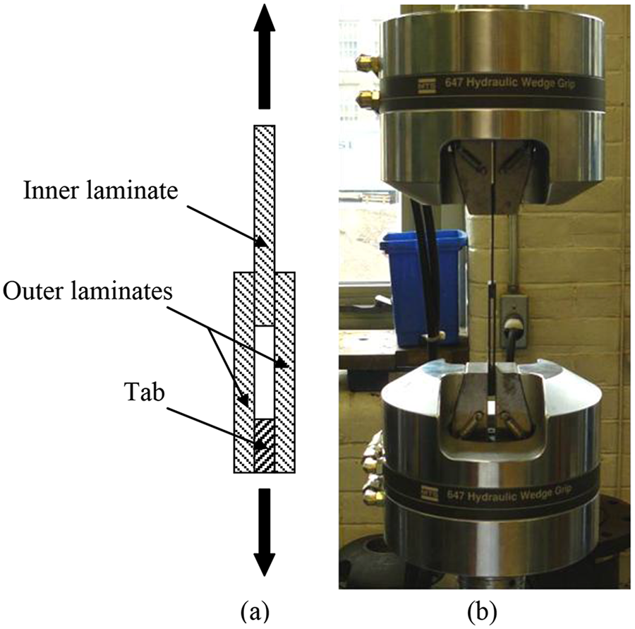
(a) Schematic representation of a DLS specimen and (b) picture of the test set-up.
where P max is the maximum load recorded during the test and A is the welded area (12.7 × 25.4 mm2).
The results of the static tests were used to define the load levels of the fatigue tests. A total of 13 to 20 specimens for each material were tested at load levels varying from 20 to 70% of the static DLS maximum load. Specimens were loaded with a sinusoidal waveform, at a frequency of 5 Hz and R = 0.1. MTS 100 and 60 kN servo-hydraulic machines (MTS System Corporation, Minnesota, USA) were used to conduct the tests, with the same clamping configuration as that used for the static tests. The tests were stopped when the specimens failed, and the number of cycles to failure was recorded. An indefinite fatigue life was reported when a specimen survived more than 1 million cycles. The fracture surfaces of the broken specimens were observed visually using SEM.
The cross section of the joints was examined by optical microscopy in order to evaluate the weld quality. New specimens were welded and cut at the middle of the overlap length in order to have a cross sectional view of the weld. They were embedded onto epoxy resin and polished before being observed using an Olympus microscope (Olympus Canada Inc., Ontario, Canada).
Results
Static performance
LSS of 53, 49 and 45 MPa were obtained for CF/PEEK, CF/PEKK and CF/PEI DLS specimens, respectively. After reviewing the SDs (Figure 4), the mechanical performances of the three materials are found to be very similar. It should be noted that the crystallinity of the PEEK and PEKK polymers was not controlled in the welding process with cooling rates of the order of 1500°C/min as compared to 10°C/min in typical processing cycles. This did not seem to affect the mechanical performances of these specimens as they presented LSS close to that of CF/PEI.
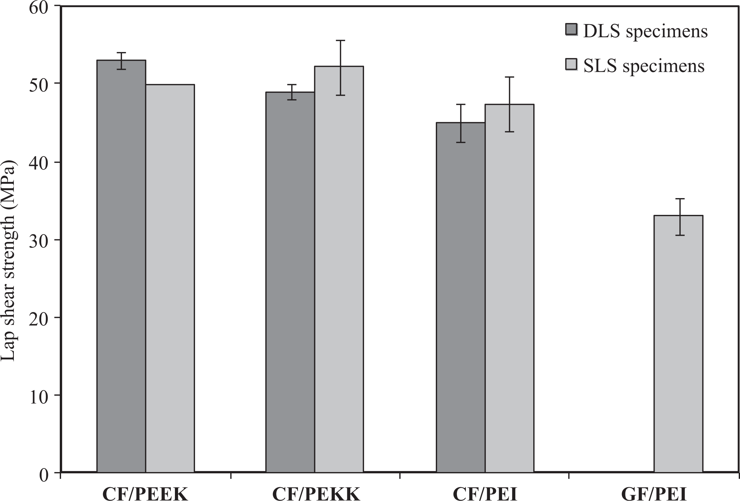
LSS comparison between SLS and DLS specimens. LSS: lap shear strength; SLS: single lap shear; DLS: double lap shear.
The mechanical performance of DLS samples was compared to that of SLS joints. 17 Both specimen types presented similar load–displacement curves. 13 The CF/PEI and GF/PEI specimens exhibited a linear behaviour up to the maximum load, which was followed by sudden failure, while the CF/PEEK and CF/PEKK specimens exhibited a linear (elastic) behaviour initially, followed by non-linear response to failure (Figure 5). Very similar LSS was also obtained in both configurations with less than 5% difference between SLS and DLS specimens for every material being tested (Figure 4). The exception is GF/PEI samples for which no LSS value was obtained for the DLS configuration. Indeed, these specimens failed in the substrate material and not in the joint. Consequently, the LSS could not be calculated for this material and can only be assumed to be the same as or higher than the laminate strength. The similarity between the two configurations was unexpected. Indeed, the reduced peel stresses in the DLS tests should have improved the performance of these specimens as it does for adhesively bonded joints. 19,20 Based on the obtained results, it can be stated that resistance-welded joints are less susceptible to peel stresses than adhesively bonded joints.
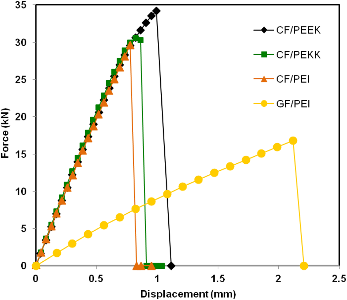
Load–displacement curves of double lap shear specimens.
Fatigue performance
The fatigue performances of DLS specimens are presented in Figure 6 as a plot of the maximum cyclic apparent stress versus the number of cycles to failure (S–N curve). The fatigue performances of all materials are similar, as the slopes of the maximum stress versus the number of cycles to failure are more or less the same. In terms of absolute stress, CF/PEEK specimens exhibited better performance, as could be expected from the static tests. Since no LSS could be found from the static tests of GF/PEI specimens, the LSS was extrapolated from the S–N fatigue curve, as shown by the dashed line in Figure 6. A value of 34 MPa was found, which is very close to the LSS of 33 MPa for the SLS GF/PEI specimens. 13 This is consistent with the observations made with the other materials, which presented similar LSS values for both SLS and DLS configurations.
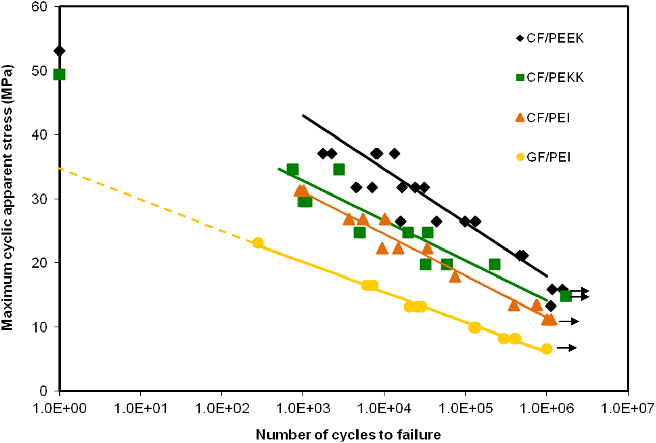
Fatigue performance of CF/PEEK, CF/PEKK, CF/PEI and GF/PEI DLS specimens. CF: carbon fibre; PEEK: polyetheretherketone; PEKK: polyetherketoneketone; PEI: polyetherimide; GF: glass fibre; DLS: double lap shear.
Fatigue results obtained here for DLS joints were compared with the results of previous studies conducted on SLS joints. 14,15 They are plotted in terms of percentage of apparent static strength versus the number of cycles to failure in Figure 7. Very similar fatigue behaviours were observed for CF/PEEK, CF/PEKK, CF/PEI and GF/PEI SLS and DLS specimens. For all materials, indefinite fatigue life occurred at approximately the same load levels for SLS and DLS specimens as summarized in Table 1. The similarity between the DLS and the SLS configuration for each material is unexpected, as these results are very different from those obtained for adhesive bonding. Unlike adhesively bonded joints, the resistance-welded DLS configuration does not enhance the joint’s mechanical performance, even under fatigue loading. This important finding suggests that welded joints are less susceptible to peel stresses than adhesively bonded joints.
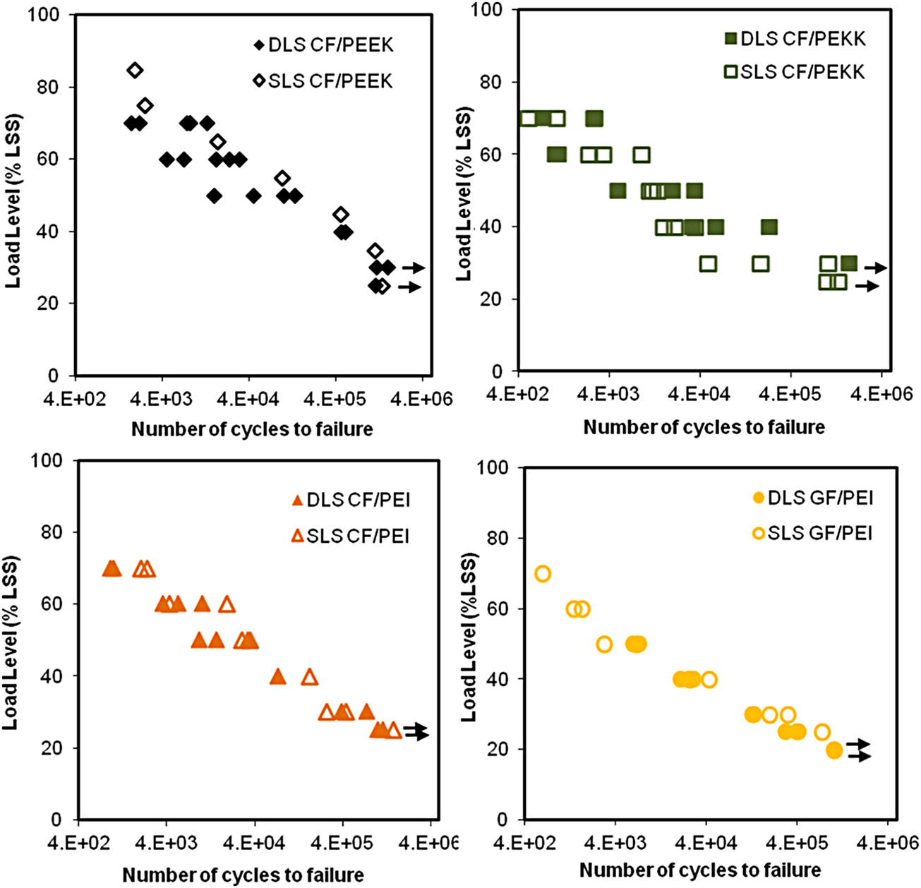
Comparison between fatigue performances of DLS and SLS specimens. DLS: double lap shear; SLS: single lap shear.
LSS at which indefinite fatigue life was reported for SLS and DLS specimens.
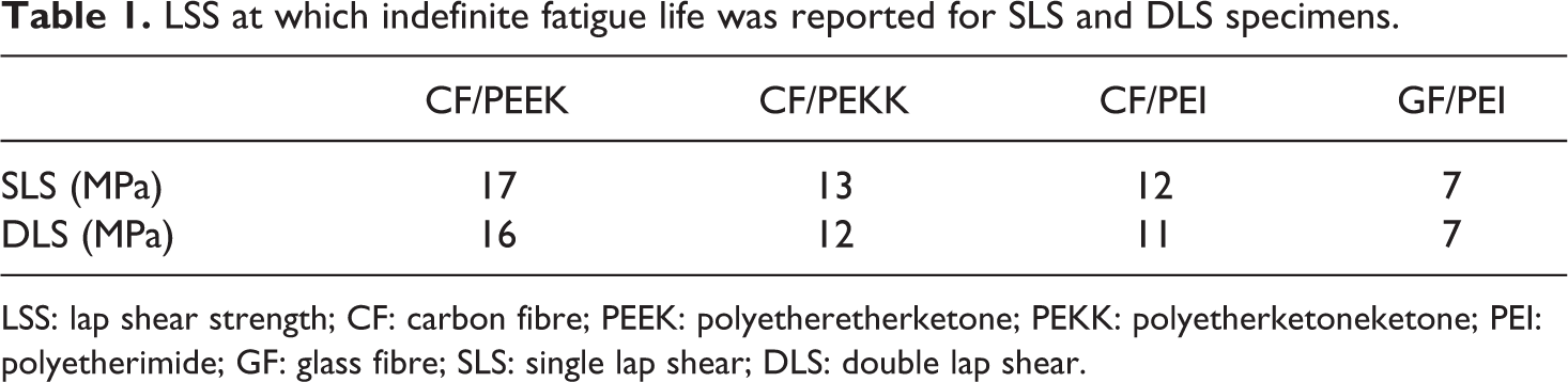
LSS: lap shear strength; CF: carbon fibre; PEEK: polyetheretherketone; PEKK: polyetherketoneketone; PEI: polyetherimide; GF: glass fibre; SLS: single lap shear; DLS: double lap shear.
Failure modes
Three different failure modes are generally observed for lap shear testing: interlaminar, interfacial and coupon failure. 3 The failure is considered interlaminar when it occurs within the laminate (tearing of the laminate), in the heating element (tearing of the heating element) or within both of them. The failure is called interfacial when it occurs at the interface between the laminate and the heating element. The coupon failure occurs when the tensile strength of the material is lower than its weld shear strength, and hence the material fails before the weld does. The tested specimens exhibited an interlaminar failure mode both in static and in fatigue, with tearing of the heating element and laminate, for all materials except GF/PEI. The GF/PEI specimens exhibited interlaminar failure at low load levels only and coupon failure in all the cases. Typical fracture surfaces are shown in Figure 8. For CF/PEI, most of the damages occurred within the laminate, with fibres being ripped off the laminate. For CF/PEEK, most of the damages occurred in the heating element and the laminates remained intact. Failure in the CF/PEKK specimen occurred in both the heating element and laminate. These failure modes reveal the degree of adhesion between the heating element and the polymer. PEI provided a stronger adhesion to the heating element than PEEK. In effect, the heating elements used to weld PEEK specimens are fully visible on the fracture surfaces, showing clear debonding between the heating element and PEEK. PEKK specimens exhibited partially welded behaviour.
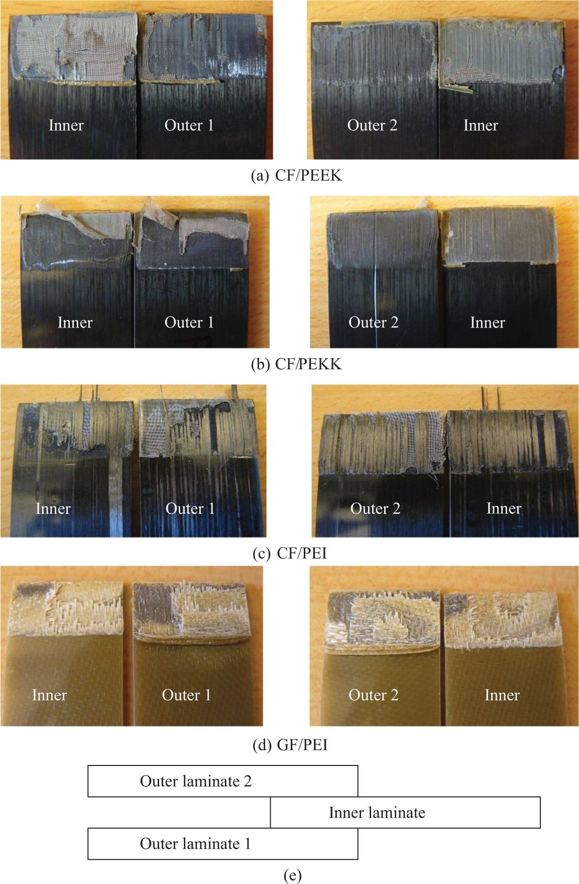
Typical fracture surfaces of (a) CF/PEEK, (b) CF/PEKK, (c) CF/PEI and (d) GF/PEI specimens, tested under fatigue loading. (e) Schematic representation of the specimen. CF: carbon fibre; PEEK: polyetheretherketone; PEKK: polyetherketoneketone; PEI: polyetherimide; GF: glass fibre.
A typical fracture surface obtained by SEM is presented in Figure 9 for a CF/PEKK specimen. Various regions such as fibres from the inner laminate, resin-rich region, heating element and fibres from the outer laminate can be identified. Figure 10 shows the fibres and the heating element impregnation. Good polymer–fibre adhesion can be seen on the micrographs (Figure 10(a)); however, a weaker adhesion is observed between the heating element and the polymer (Figure 10(b)).
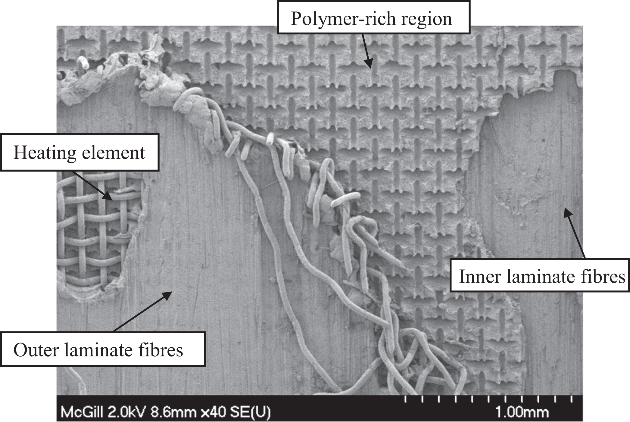
Typical fracture surface of CF/PEKK DLS specimens tested under fatigue loading. CF: carbon fibre; PEKK: polyetherketoneketone; DLS: double lap shear.
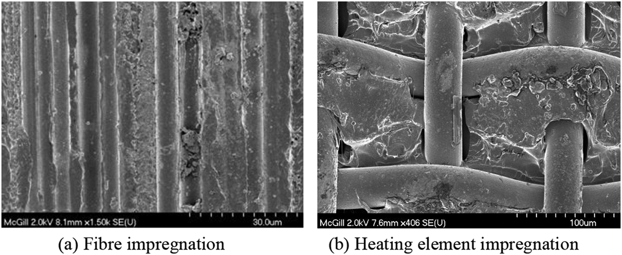
Scanning electron microscopic image of (a) fibre impregnation and (b) heating element impregnation.
Interface quality characterization
Following the welding operation, the specimens were cut and polished in order to observe the cross sections under an optical microscope. Both the centre and edges of the welds were observed. Figures 11 and 12 show cross sections of CF/PEKK and CF/PEI specimens, respectively. At the centre of the joints, good weld quality is obvious without any void or porosity. The heating element was completely impregnated with the polymer, which led to mechanical interlocks. At the edges of the joints, polymer squeeze out and overheating due to the local edge effects created some porosities. These observations are in good agreement with the ones made on the SLS configuration. 14 PEI samples exhibited more voids at the edge of the joint than PEEK or PEKK. This is explained partly by the lower environmental resistance of PEI, in comparison with PEEK or PEKK. Molten PEI also has a lower viscosity than PEEK and PEKK, resulting in more polymer being squeezed out of the weld. Polymer squeeze out may result in a lower pressure at the edges of the welds, which affects consolidation at this particular location.
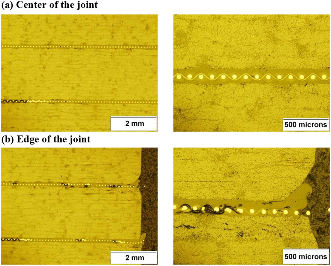
Micrographs of the cross section of a DLS CF/PEKK specimen. DLS: double lap shear; CF: carbon fibre; PEKK: polyetherketoneketone.
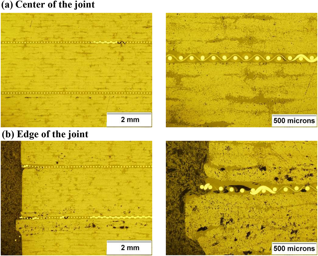
Micrographs of the cross section of a DLS-CF/PEI specimen. DLS: double lap shear; CF: carbon fibre; PEI: polyetherimide.
Conclusion
The objective of this research was to study the effect of the resistance-welded joint geometry, that is, SLS or DLS specimen, on the static and fatigue mechanical performances. DLS specimen geometry is known to lead to better mechanical performance in the case of adhesively bonded joints, due to the lower peel stresses induced at the joint. This study led to different results for resistance-welded joints. LSS of 53, 49 and 45 MPa were obtained for DLS CF/PEEK, CF/PEKK and CF/PEI specimens, respectively. These LSS are no different from the ones obtained for SLS specimens. The fatigue performance of the DLS specimens is also quite similar to that of SLS joints with same S–N curves, and indefinite fatigue lives were obtained at load levels varying between 20 and 30% of the static LSS. This performance in fatigue shows once again the lower sensitivity of the welded joints to the out-of-plane stresses, as compared to the adhesively bonded joints. This good resistance to peel stresses counts as another advantage of using thermoplastic composites as opposed to thermosetting composites.
Footnotes
Acknowledgements
The authors would like to gratefully acknowledge Cytec Engineered Materials Inc. and Ten Cate Advanced Composites for providing the materials.
Funding
This work was supported by funding from the Canada Research Chair in Advanced Composite Materials and the National Research Council of Canada.