
Abstract
To address the inaccurate contour error calculation problem in traditional cross-coupled control (CCC) methods for biaxial motion systems, this paper presents a novel CCC method based on a recently developed tangential velocity tracking (TVT) strategy. It has the advantage that existing high-precision algorithms for searching the foot point can be directly integrated to obtain the excellent estimation accuracy of contour error. The cumbersome parameter tuning for position controllers of each axis is unnecessary. Moreover, a velocity interpolator for parametric curves is developed to extend the TVT strategy to the variable feedrate case. The stability of the TVT-based CCC system is proved using a quadratic Lyapunov function. Comparative experiments are carried out, and the results indicate that the estimation deviation of contour error in the TVT-based CCC method can be constrained within 1 μm. The maximum contour error is significantly reduced by 65.32% and 50.10% compared with the traditional CCC methods based on tangential and circular approximations, respectively.
Introduction
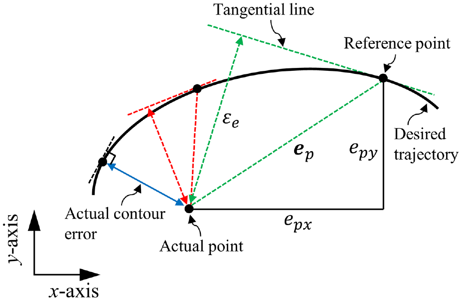
Contouring control is widely used in industrial applications, including computer numerical control (CNC) machine tools, laser cutting, robot manipulators, etc. In contouring control systems, each axis must follow a predetermined trajectory simultaneously. A critical measure of final product quality is the contour error,1–3 which is geometrically the shortest distance between the desired trajectory and the actual position. In traditional contouring control methods, each axis is designed independently, and the control task is to reduce position tracking errors of each axis. Accordingly, the contour error can be indirectly reduced to some extent. Nonetheless, perfect position tracking control of each axis is hardly achieved. Moreover, purely reducing position tracking errors does not necessarily improve the contouring performance in theory. 4
To address the problem, Koren and Lo5,6 pioneered the cross-coupled control (CCC) strategy for biaxial contouring control systems. In the CCC strategy, an additional contouring controller composed of a real-time contour error calculation algorithm and a control law is added to individual axial control loops. The basic idea of the CCC strategy is to generate contour error correction signals according to the estimated contour error and the control law, then distribute them into velocity control loops of each axis to reduce the contour error. Due to its simplicity, the CCC strategy receives more attention and has become popular in contouring control. 7 At present, different control laws, including fuzzy PID control 8 and deep reinforcement learning, 9 have been integrated into the CCC strategy to improve contouring performance under external disturbances. Meanwhile, advanced individual tracking control algorithms, such as sliding mode control, 10 model prediction control, 11 and iterative learning control, 12 have been combined with the CCC strategy to simultaneously minimize the contour error and the position track errors of each axis. Recently, the CCC strategy has been applied to the five-axis machine tools. 13
Note that the CCC is a feedback controller, and the contouring performance in CCC systems depends on the real-time estimation accuracy of contour error. Generally, the analytical solution of contour error for straight lines and circular trajectories can be directly obtained. Nevertheless, in reality most trajectories are represented in a complex form, and calculating the actual value of contour error is impractical. To address this problem, many researchers have proposed various contour error estimation methods (CEEMs) in the past decades, which can primarily be classified into two categories: the geometric approximation-based CEEM and the iterative search-based CEEM.
In the geometric approximation-based CEEM, the desired trajectory is approximated locally by the tangential line14,15 or the osculating circle 16 at the current reference point. Then, the distance from the actual point to the tangential line or the osculating circle is taken as the estimation value of contour error. The geometric approximation-based CEEM is simple and easy to implement in practice. Note that the high estimation accuracy of contour error in the geometric approximation-based CEEM is achieved only when the actual point is close enough to the reference point. Although the CCC strategy has been combined with many advanced control algorithms for improving the position tracking performance of each axis, 17 significant position tracking errors of each axis may exist because of the uncertain external disturbances and the bandwidth limitations of motors and drivers.
As an alternative method, the iterative search-based CEEM aims to search the foot point, that is, the point closest to the current actual position in the desired trajectory. Geometrically, the vector from the foot point to the actual point is perpendicular to the desired trajectory. According to this property, the foot point can be searched accurately by tangential or circular backstepping methods.18–20 Meanwhile, Newton’s method21–23 and Brent’s method 24 were developed to search the foot point in a numerical calculation way. Recently, Wang et al. 25 realized a faster convergence rate based on Atiken acceleration for better real-time performance. The iterative search-based CEEM can achieve perfect estimation accuracy of contour error. However, it is necessary to point out that the stability analysis of CCC systems using the iterative search-based CEEM is still challenging.26,27
Recently, a novel contouring control framework based on the tangential velocity tracking (TVT) strategy has been proposed to eliminate the adverse effect of position tracking errors on the estimation accuracy of contour error. 28 Furthermore, the task coordinate frame method for biaxial motion control has been developed successfully based on the TVT strategy. However, it requires precision dynamics models and can only be used in the case of constant feedrate.
This paper will apply the TVT strategy to the CCC system to address the inaccurate contour error estimation problem. In the proposed TVT-based CCC method, the feed-direction control task is completed by tracking the desired tangential velocity command. The desired feedrate at the current foot point is calculated in real time. The error dynamics of the control system are derived, and the system stability is proved using a quadratic Lyapunov function.
The main contributions of this paper can be summarized as follows:
(1) An innovative contouring control structure is proposed. It cancels the individual axial position tracking, avoiding the parameter tuning of position controllers that is particularly cumbersome. Different iterative search-based CEEMs for seeking the foot point can be directly integrated to achieve accurate contour error estimation. Moreover, the system stability is guaranteed.
(2) Extend the TVT strategy to the variable feedrate case by developing a velocity interpolator for biaxial parametric curves.
The rest of this paper is organized as follows. Section 2 briefly discusses the traditional velocity-loop CCC method. In Section 3, we propose a novel TVT-based CCC method. The experiments are carried out and analyzed in Section 4. The conclusions are summarized in Section 5.
Traditional velocity-loop CCC method
Figure 1 shows the typical structure of the traditional velocity-loop CCC method for biaxial motion systems.

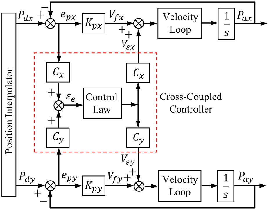
Typical structure of the traditional velocity-loop CCC method for biaxial motion systems.
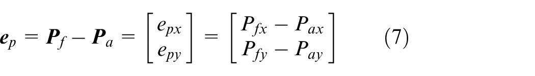
For example, the contour error for a linear trajectory can be determined by 6

where
The first one is the CEEM for the real-time calculation of
Tangential line-based CEEM.
The second one is to distribute the control effort to minimize position tracking errors and the estimated contour error simultaneously. As shown in Figure 1, different position control objectives exist in the feed and contouring directions. The feed-direction control objective is to reduce the position tracking errors (
The last but not least one is the stability analysis. Because of the time-varying and coupled properties of the CCC system, it is difficult to analyze the system stability, especially when using the iteration search-based CEEM.26,27
TVT-based CCC method
In this section, a novel TVT-based CCC approach is proposed. The contouring control framework is first introduced. Then, a velocity interpolator for parametric curves is developed to obtain the curve parameter-based tangential velocity commands. Finally, the error dynamics of the control system are derived, and the system stability is proved using a quadratic Lyapunov function.
Contouring control framework
In practical applications, the contouring-direction control task is to eliminate the contour error, while the feed-direction control task is to make the end-effector (e.g. tools) move along the desired trajectory with the desired feedrate. In traditional CCC methods, the feed-direction control is designed such that each axis must track the reference point according to the sampling time. As a result, the position tracking errors in the feed direction would degrade the estimation accuracy of contour error. Recently, a new contouring control framework based on the TVT strategy has been proposed. 28 To eliminate the adverse effect of position tracking errors on the estimation accuracy of contour error, the feed-direction control task in the TVT strategy is completed by tracking the desired tangential velocity according to the estimated foot point. Note that the point closest to the current actual position in the desired trajectory is referred to as the foot point in this paper.
Accordingly, we propose a TVT-based CCC method for biaxial motion systems, as shown in Figure 3. In Figure 3(a),
(1) Search for the foot point according to the current actual point
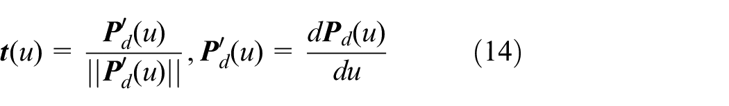
(2) Calculate the unit tangential vector

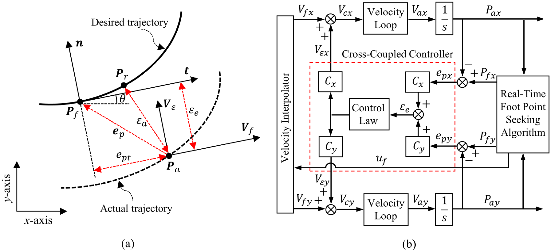
TVT-based CCC method for biaxial motion systems: (a) schematic diagram and (b) control structure.
The unit normal vector

(3) The velocity interpolator determines the desired tangential velocity command
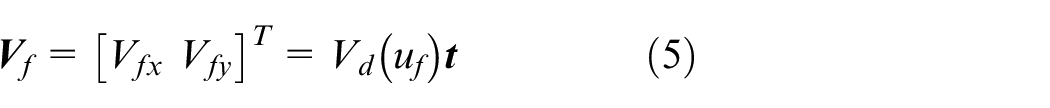
where
(4) As shown in Figure 3(a), the contour error is estimated by the distance from

where 〈·〉 denotes the inner product operator, and
Accordingly, the cross-coupled gains

(5) As shown in Figure 3(b), the CCC generates the velocity command
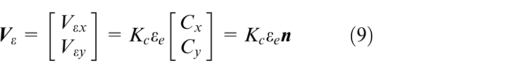
where
(6) Finally, the velocity commands of each axis shown in Figure 3(b) are given by


Note that
Curve parameter-based tangential velocity interpolator
The traditional interpolator parameterizes the desired trajectory as a function of time and calculates the reference point at each sampling instant. However, for the TVT-based CCC approach shown in Figure 3(b), the interpolator must determine the desired tangential velocity
Recall that the magnitude of
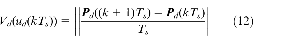
where ||·|| denotes the Euclidean norm.
For the arbitrary curve parameter
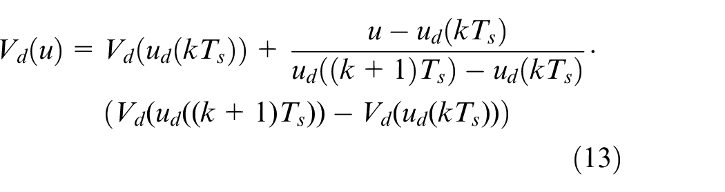
Note that
Thus, we have

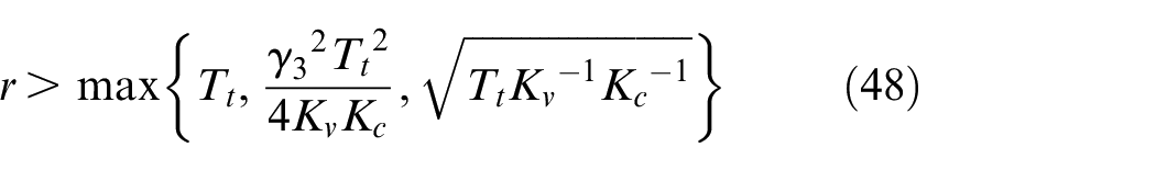
where
Error dynamics of the TVT-based CCC system
For most typical feed drive systems, the velocity closed-loop dynamics can be reasonably modeled as a first-order system,30,31 which is described in the Laplace domain as follows:
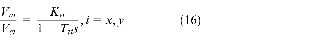
where

In practical applications, it is essential to tune the velocity controller parameters to match axial dynamics. Hence, we assume that the mismatch of velocity closed-loop dynamics between the x-axis and y-axis can be negligible, that is,


where
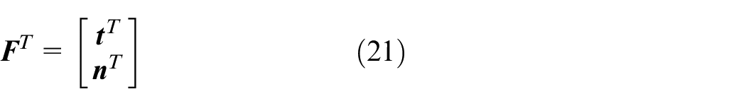
As seen from Figure 3(a), we can define a new local coordinate frame composed of the orthogonal unit vectors

where
Note that
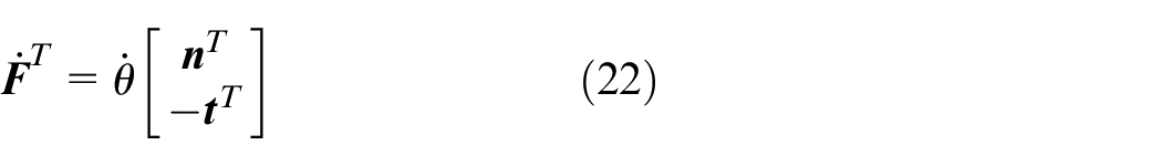
where
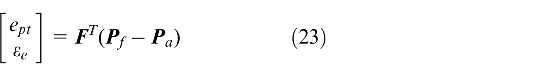
By letting
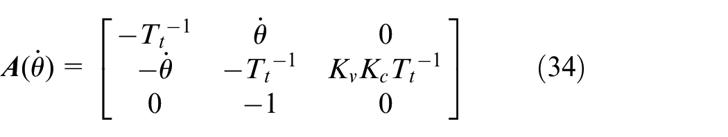
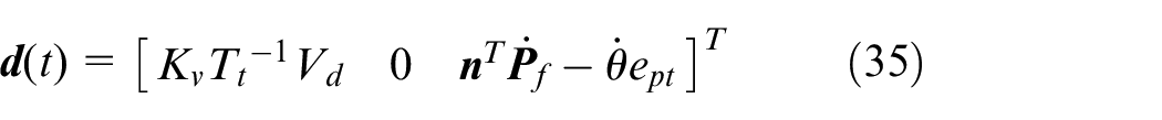
where

In (25),
It can be seen from (10) that the desired velocity command

Accordingly, using (5) and (9), we can obtain
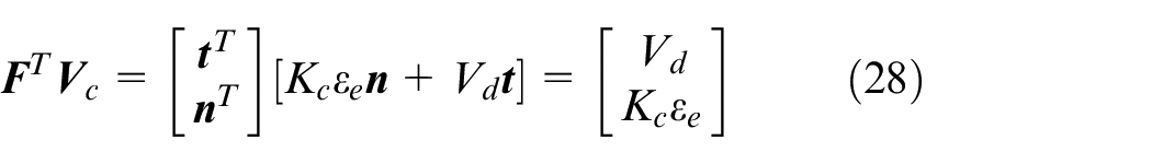
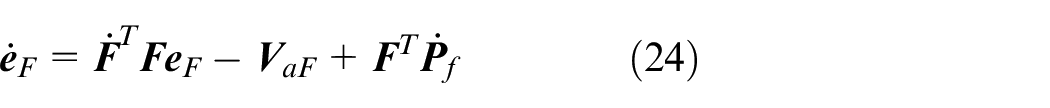
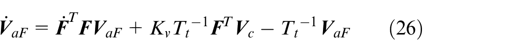
Substituting (21), (22), and (28) into (26) yields


Similarly, substituting (21) and (22) into (24) yields

From (29) to (31), the resulting error dynamics of the TVT-based CCC system have the following form:

where

Note that
Stability analysis
This subsection first gives a necessary and sufficient condition for positive definite matrices and a sufficient condition for quadratic stability. Then, the system (32) without the disturbance input is proved to be quadratically stable, which is used to further prove that the solution of the TVT-based CCC system is bounded.

where
Define the scalar valued function

where

Let

If

Note that ||·|| denotes the norm for vectors and the corresponding induced norm for matrices hereafter. When the condition (39) is satisfied, (37) is a quadratic Lyapunov function of the system (36).
Then,
Let us consider the following system simplified from (32):

where
Note that
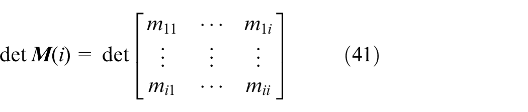
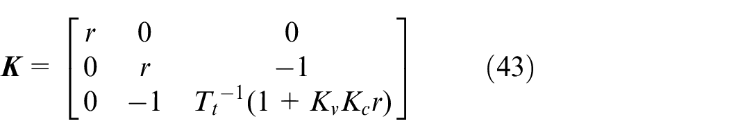
Let
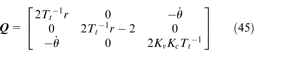
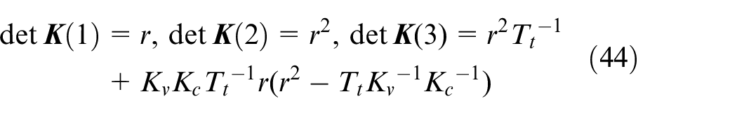
Accordingly, all its leading principal minors are
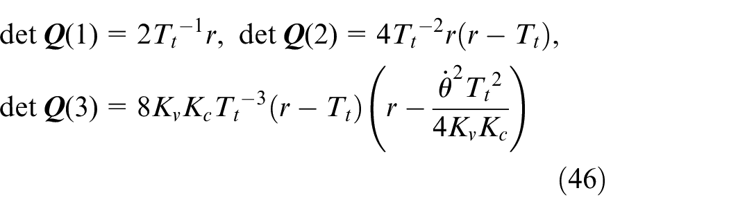
For a regular desired trajectory,
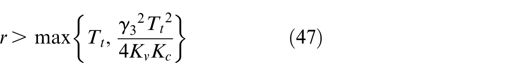
all leading principal minors of
To sum up,
Then, both
Based on Theorem 3, the stability of the TVT-based CCC system can be proved.
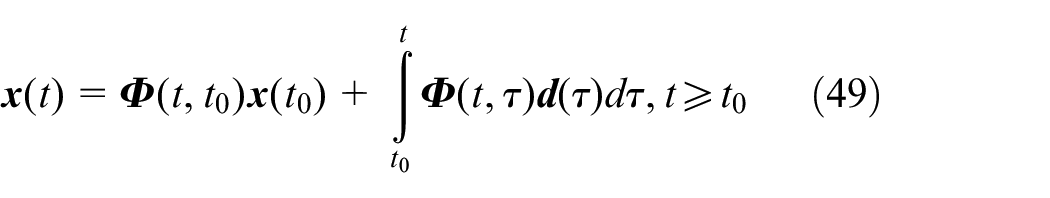
Proof: Let
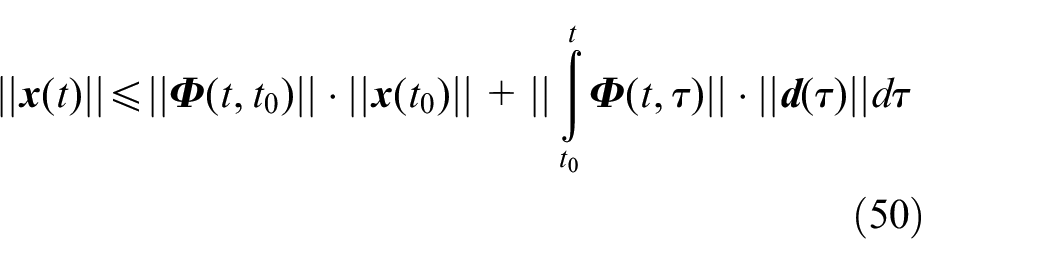
Taking the norms of both sides of (49) yields the inequality
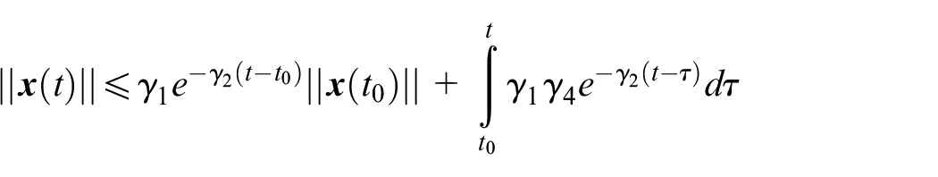
For a regular desired trajectory, both

Because the system (42) is quadratically stable according to Theorem 3, the state-transition matrix
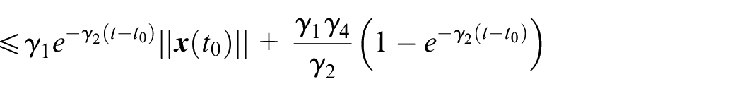
which completes the proof.
From Theorem 4 and (33), the actual velocities
Experimental investigation
Experimental setup
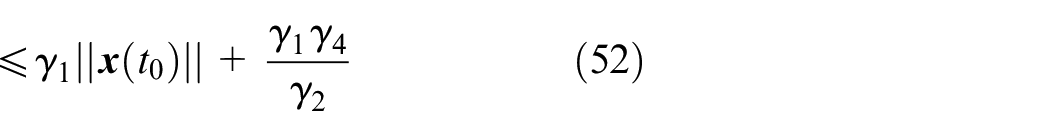
Comparative experiments were carried out to verify the effectiveness of the proposed TVT-based CCC method. The three-axis motion control system shown in Figure 4 was used. The MATLAB/Simulink desktop real-time software (Version 10.4, R2021b), which can provide a real-time kernel for Windows, implements the control algorithms in the personal computer (PC) with a sampling interval of 1 ms. An ARM-based controller board converts the digital commands of the PC into the actual input voltage of the AC servo drivers over digital-to-analog converters (DACs). Meanwhile, the board collects position signals with a resolution of 0.5 μm by the encoder interfaces and feeds them back to the PC.
Three-axis motion control system.
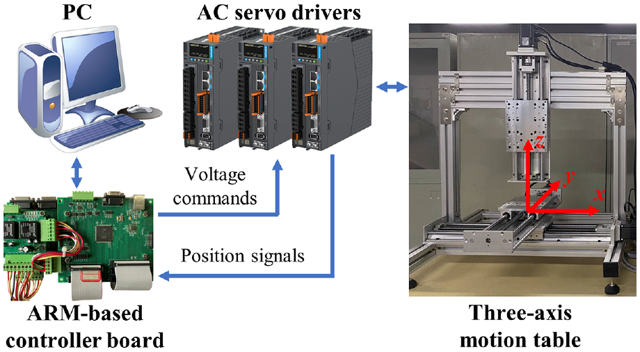
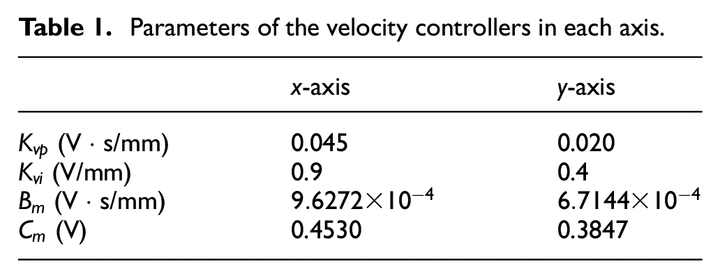
To improve the velocity tracking performance, the velocity controller of each axis consists of a PI-type feedback controller and a feedforward controller for the friction compensation, as depicted in Figure 5, where

where
Block diagram of the velocity controller in each axis.
Parameters of the velocity controllers in each axis.
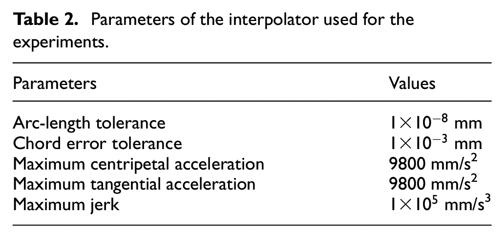
The butterfly-shaped curve shown in Figure 6(a) was applied in experiments. The parametric interpolator developed by Liu et al. 29 was used to generate the time-stamped position commands offline, and the parameters used for the experiments are listed in Table 2. For the proposed TVT-based CCC method, the time-stamped position commands can be further converted into the curve parameter-based tangential velocity commands through the algorithm described in Subsection 3.2. Figure 6(b) shows the feedrate versus curve parameter when the maximum feedrate is set to 100 mm/s.
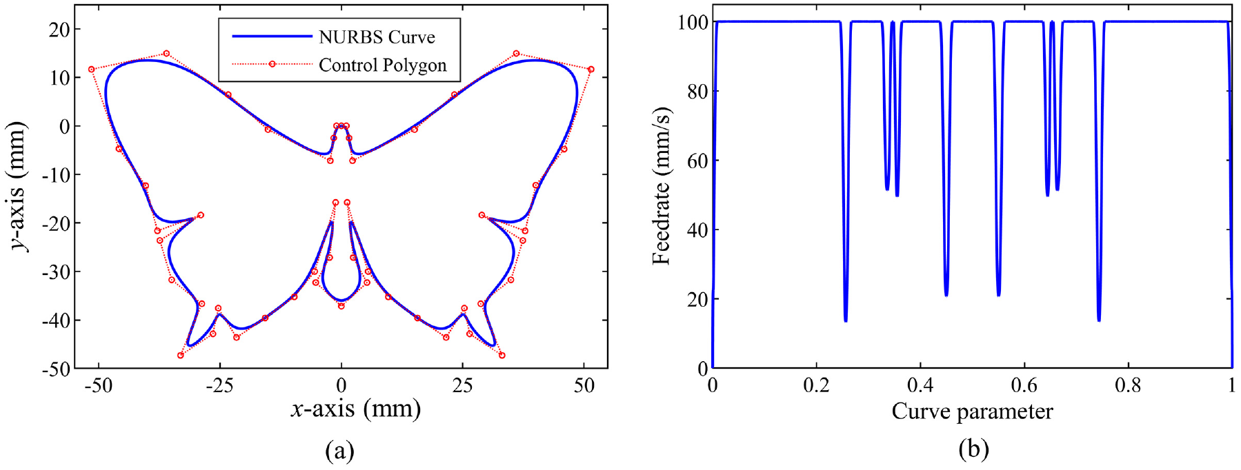
Desired trajectory and the corresponding feedrate: (a) butterfly-shaped curve and (b) feedrate versus curve parameter with the maximum feedrate of 100 mm/s.
Parameters of the interpolator used for the experiments.
Three methods were conducted for comparison: the traditional velocity-loop CCC methods with the tangential line-based CEEM
14
(C1) and osculating circle-based CEEM
16
(C2), and the proposed TVT-based CCC method (C3). In C3, the foot point was searched by the tangential-error backstepping method
20
with the maximum iteration number of 10 and the limited tangential error of 1 μm. The proportional gains of position controllers in the x-axis and y-axis were set to 40 s−1 for C1 and C2, while there is no need for C3 to tune the parameters of position controllers. Note that
Experimental results
The estimation accuracy of contour error in the three methods was first verified. The experiments were carried out with the maximum feedrate of 100 mm/s, and the proportional gain
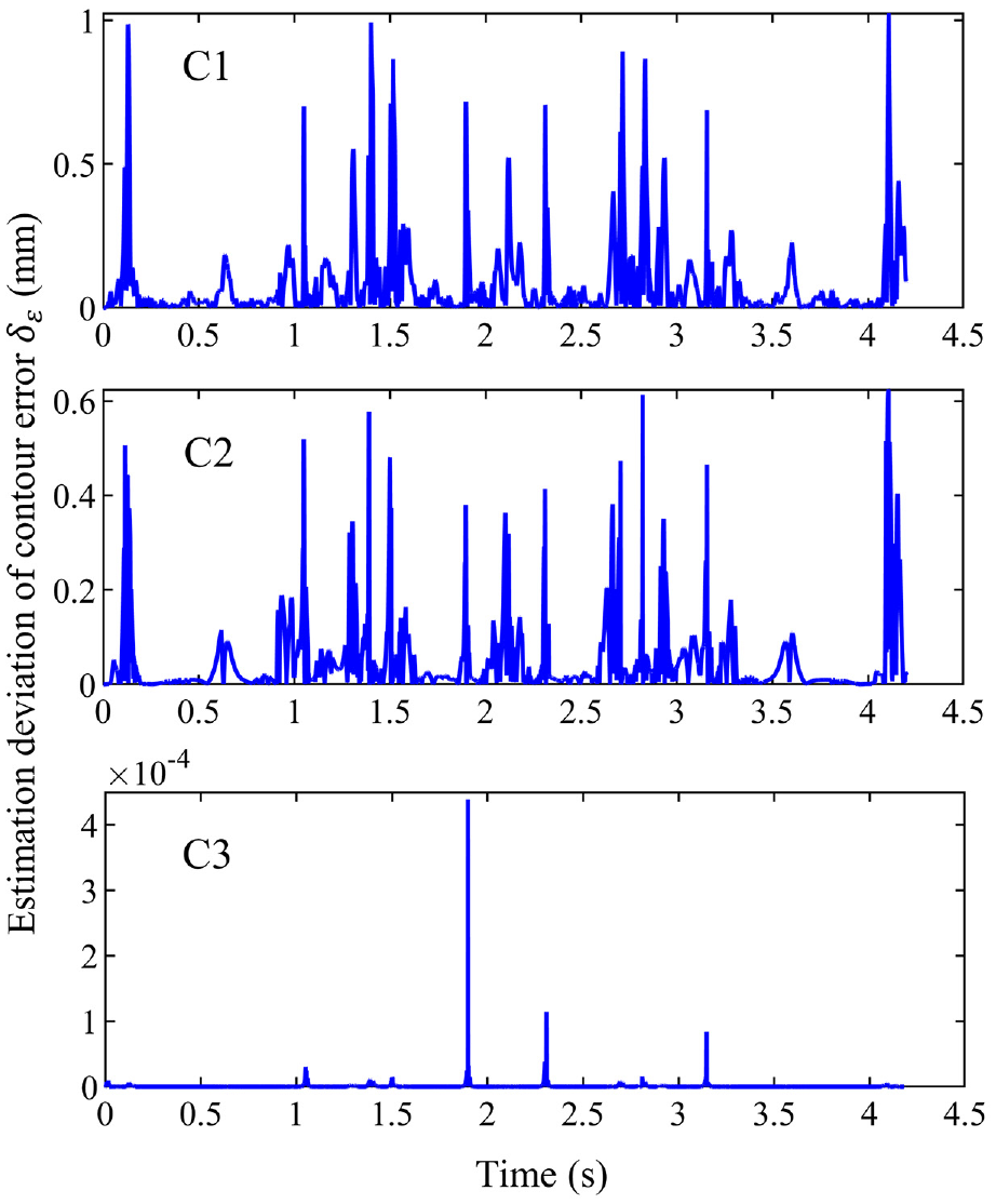
Estimation deviations of contour errors in the three methods when the proportional gain of the CCC was set to 140 s−1.
The second experiment was conducted to test the contouring performance. The proportional gain
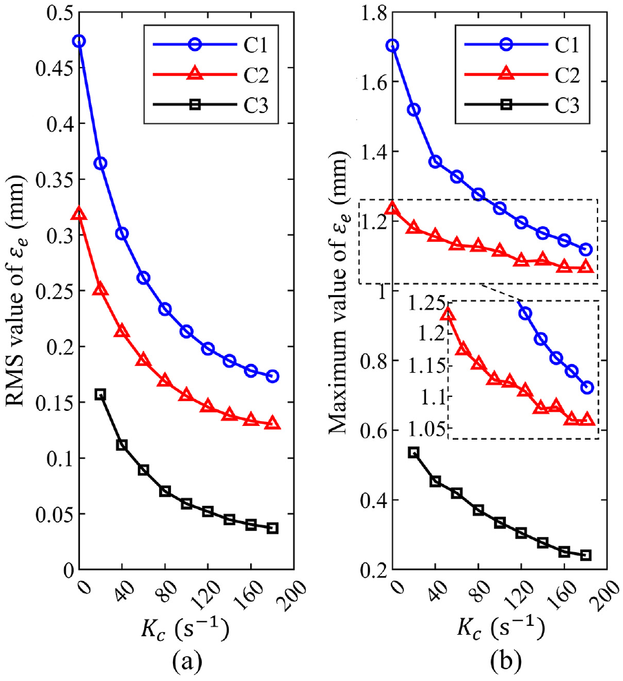
Performance indexes of estimated contour errors with different proportional gains of the CCC: (a) RMS values and (b) maximum values.
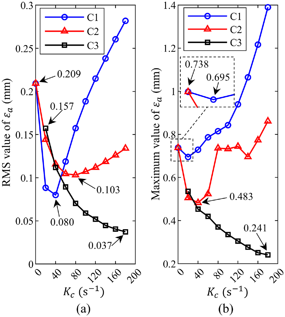
Performance indexes of actual contour errors with different proportional gains of the CCC: (a) RMS values and (b) maximum values.
From Figure 9, when
It should be noted from Figure 8 that the RMS value of
For C3 with the nearly perfect estimation performance, both the estimated and actual contour errors decrease monotonically with respect to the proportional gain
To investigate the dependence of contouring performance on the feedrate, the experiments were carried out for the maximum feedrate from 50 to 150 mm/s with an increment of 10 mm/s. The proportional gain of the CCC was set to 140 s−1. Figure 10 illustrates the RMS values of
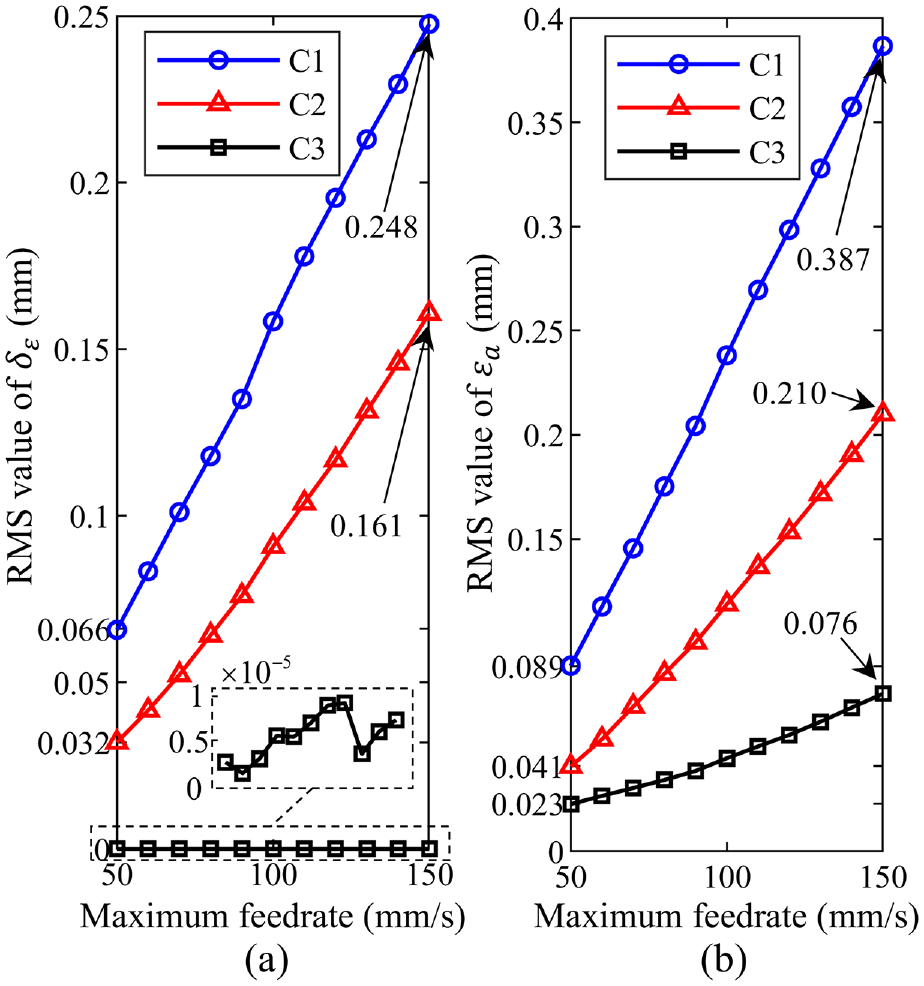
Dependence of contouring performance on the feedrate: (a) RMS values of estimation deviations of contour errors and (b) RMS values of actual contour errors.
From Figure 10(b), the RMS values of
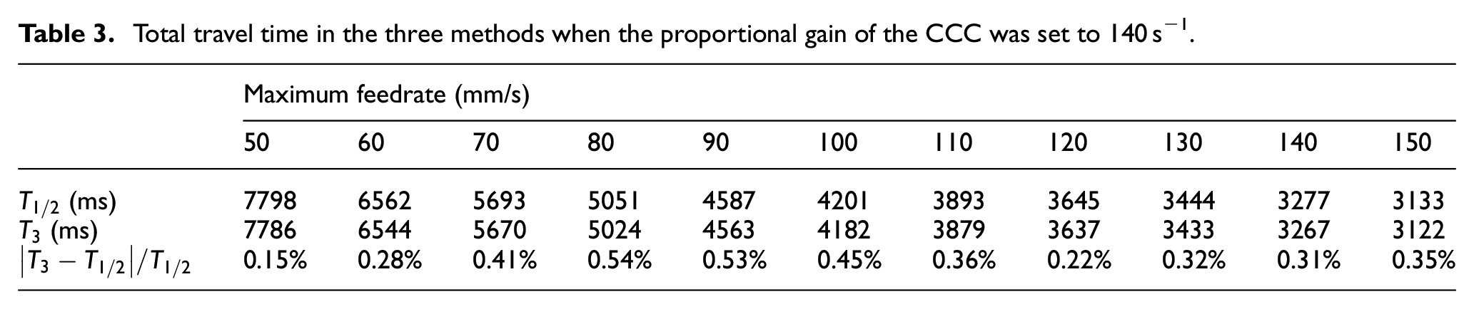
Table 3 lists the total travel time in the three methods when the proportional gain of the CCC was set to 140 s−1. Although the total travel time
Total travel time in the three methods when the proportional gain of the CCC was set to 140 s−1.
Conclusion
The position tracking errors in the feed direction deteriorate the estimation accuracy of contour error in the traditional CCC method with geometric approximation-based CEEMs. This paper proposes a novel TVT-based CCC method. The feed-direction control task is completed by tracking the tangential velocity command, thus avoiding the cumbersome parameter tuning of individual axial position controllers. The contour error estimation is rather accurate by calculating the distance from the actual point to the tangential line at the foot point. Meanwhile, the system stability is guaranteed. Comparative experiments demonstrate that the proposed TVT-based CCC method can achieve outstanding contouring performance in high-speed and large-curvature contouring tasks because of the accurate contour error estimation. Note that only a simple P-type controller is used in the presented TVT-based CCC method. Future research will focus on designing advanced control laws to improve the contouring performance under external disturbances. Moreover, it will be interesting to apply the TVT strategy to three- and five-axis machine tools.
Footnotes
Declaration of conflicting interests
The author(s) declared no potential conflicts of interest with respect to the research, authorship, and/or publication of this article.
Funding
The author(s) disclosed receipt of the following financial support for the research, authorship, and/or publication of this article: This work was supported by the National Natural Science Foundation of China [grant numbers 51605328, 51975402].
Data availability statement
The data used to support the findings of this study are available from the corresponding author upon request.