
Abstract
In this article, the three-axis motion platform built by linear motor is taken as the research object, and a new control scheme is designed to solve the problems of low operation accuracy and response speed when the three-axis motion system completes the spatial contour tracking task. This article establishes the spatial contour error model and effectively reduces the spatial contour error by designing an adaptive super-twisting decoupling sliding mode controller. At the same time, based on the finite-time reachability theory and adaptive control theory, the control strategy adopted in this article can improve the response speed of the system. And, the parameters of the controller can be adjusted adaptively according to the disturbance, thus enhancing the robustness of the system. The effectiveness of the control strategy is verified by simulation and experiment.
Keywords
Introduction
With the development of modern technology, machines need to perform more and more complex tasks to meet the needs of industry. In order to improve the performance of complex structure mechanical system, the research on the control algorithm of this kind of working platform is very important.
In this article, the working platform of three-axis linear motor is taken as the research object. In order to improve the operation accuracy, the spatial contour error model of multi-axis linear motor should be established first. In previous studies,1–5 the contour error model of the three-axis motion platform is established. However, they all have the disadvantages of complex mathematical model and large amount of calculation. The system has high requirements for hardware equipment and software programming, which are not conducive to practical application. In order to effectively reduce the profile error in the three-axis control system and improve the response speed of the whole system. In this article, after comprehensive consideration of various mathematical models of contour error, the contour error is obtained by calculating the uniaxial position error, tangential velocity of contour, and corresponding unit normal vector at a certain moment.
For the control algorithm of complex machinery, researchers combine its motion characteristics and constantly enrich its control strategy. Sliding mode variable structure algorithm (sliding mode controller (SMC)) with its simple structure and strong operability obtained the swift and violent development in recent years. In Ren et al., 6 an adaptive sliding mode algorithm is designed, which combines the advantages of convergence and adaptive algorithm in finite time of the sliding mode algorithm to solve the uncertain boundary problem. In the control application of the brush motor, good results are obtained. In Wai and Muthusamy, 7 a fuzzy-neural-network-inherited SMC (FNNISMC) scheme is proposed to relax the requirement of detailed system information and deal with chattering control efforts in the SMC system. By taking advantage of the neural network’s self-learning, strong anti-disturbance ability is achieved, and by combining with the characteristics of fast convergence of the sliding mode control structure, the motion trajectory tracking ability of the manipulator can be significantly improved. It can be seen that the sliding mode control structure has strong fusion ability with other complex algorithms,8,9 which can give full play to its advantages. However, many complex algorithms are combined with the first-order sliding mode, which cannot avoid the chattering problem caused by the structure of the sliding mode. At the same time, neural network learning, online system parameter identification, and other complex control strategies combined with sliding mode have perfect performance in theory, but they are difficult to be applied in practical engineering due to the hardware basis and the complex working conditions of actual industrial systems. In order to reduce system chattering, the development of high-order sliding mode algorithm has attracted people’s attention. In Huang et al., 10 it is pointed out that the theoretical development of high-order sliding mode control in traditional sliding mode is to avoid jitter while maintaining the main advantages of SMC. This control technique extends the traditional sliding mode control idea that the time derivative acting on the high-order sliding mode variable replaces the first derivative acting on it. This scheme has strong robustness, which makes it attractive to drive control research. Previous works11–13 mainly study the second-order sliding mode theory and its application characteristics, and provide a method to prove the stability of the second-order SMC. It provides a solid theoretical foundation for the practical application of second-order sliding mode. Unfortunately, the theory of high-order sliding mode is still not perfect. For the application of high-order sliding mode, more emphasis is placed on theoretical analysis, and there is a lack of deeper engineering practice.
After summarizing the above literatures, this article first establishes the spatial contour error model of the three-axis motion system. Compared with the error model of previous researchers,14,15 this model has the characteristics of strong operability and small computation. From the perspective of the actual project, to enhance the system anti-jamming capability and improve the system response speed, design the adaptive super-twisting sliding mode control algorithm for three-axis motion space contour error compensation of the system. The control strategy combines the advantages of adaptive control and sliding mode control, so that the parameters of the SMC can be adjusted according to the external disturbance. Using the super-twisting sliding mode control algorithm, when designing the control law, it is only necessary to know the sliding mode variable information, and it is not necessary to obtain the derivative information of the sliding mode variable. It has a good performance in practical engineering control and can effectively reduce the system input chattering. In this article, in order to improve the actual performance of the system, the controller is composed of two parts: the uniaxial absolute position controller and the spatial contour decoupling controller. The uniaxial absolute position controller is a classical first-order sliding mode, and spatial contour decoupling controller is an adaptive super-twisting sliding mode structure. Such a composite structure significantly improves the response speed and anti-interference ability of the system.
Establishment of contour error model
In order to achieve accurate tracking of the spatial contour, a spatial contour error model based on the three-axis control system is needed. The schematic diagram of the three-axis experimental platform given in this article is shown in Figure 1. The error between the actual motion position of the system and the given contour trajectory is calculated. In order to better illustrate the process of establishing the contour error, this article first establishes a two-dimensional contour error model and generalizes it to the three-dimensional system to establish the spatial contour error based on the three-axis control system model.
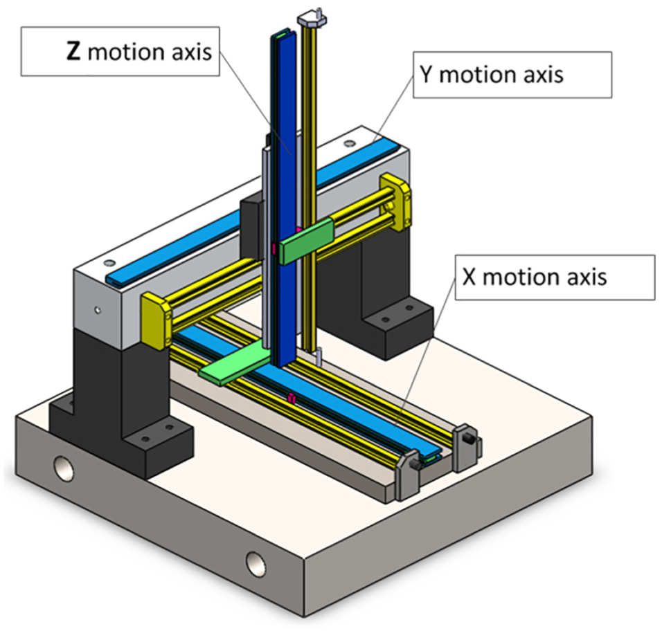
Schematic diagram of the triaxial experimental platform.
Two-dimensional contour error model
In the two-dimensional servo control system, the actual moving position of the system is set

Two-dimensional arbitrary contour curve.
In Figure 2,

In an actual multi-axis control system, the response speed of the system is critical. The amount of calculation in the program should be minimized to improve the overall response speed. Therefore, the distance

The unit normal vector

From Figure 2, the geometric relationship can be derived as

By deriving the contour error in a two-dimensional plane, in order to facilitate the calculation of the contour error of the system, the shortest distance
Three-dimensional contour error model
In the process of deriving the two-dimensional plane contour error into the three-dimensional contour error, in the three-dimensional servo control system, the actual motion position of the system is set to

Three-dimensional arbitrary contour curve.
We can define the position error as

In calculating the three-dimensional contour error, in order to reduce the overall calculation of the system, the actual spatial contour error


From the above conditions (6)–(10)


In the actual system operation process, in order to facilitate the calculation of the tangential direction vector


The contour tangent vector

The expression of the unit normal vector is obtained from equations (6), (11), and (12)
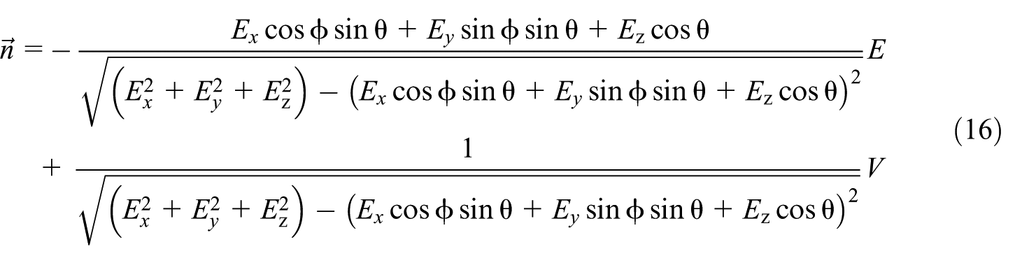
where

The final contour error can be expressed as

Design of space decoupling controller for three-axis linear motor based on SMC
Overall system control structure
The overall system block diagram designed in this article is shown in Figure 4. Single-axis position error control is performed by sliding mode control. Each time the position signal transmitted by the three-axis sensor is transmitted to the respective single-axis controller, it is also transmitted to super-twisting sliding mode space decoupling controller, which outputs the final control signal under the joint action of the single-axis controller and the spatial decoupling controller and controls the overall three-axis platform with minimal space contour error.

Control system structure.
SMC design based on steady-state error boundary
Sliding mode variable structure control is a special variable structure control. The ideal sliding mode control transitions to a stable state along the switching surface. The sliding surface around the designed sliding surface has fast switching characteristics, which can improve the system response speed and has a good anti-interference ability. Under the traditional first-order sliding mode control, the selection of the parameters of the control often adopts the trial and error method, which is often arbitrarily large and scientifically insufficient. According to the uncertainty and disturbance problem of the system, the sliding mode error bound and system uncertainty are obtained based on the Lyapunov method, and the mathematical relationship between the parameters of the power approaching law is designed. According to the requirements of the steady-state error, the design of control parameters is suitable. Consider the following class of n-order uncertain nonlinear systems

where u is the control input,
Define the system tracking control error as

where

where
The control law for the above system design is governed by the equivalent law (integrated equations (19)–(21) and set

and the power approach law

It can be defined that

where

Add the above two formulas to get

When

From the solution of s obtained by the above formula, it can be found that the state variable of the system can reach the sliding surface after a finite time, but when the system is disturbed, when
As can be seen from the above formula, when
Combining the above analysis, and by performing the Laplace transform on equation (20), by calculating the input impulse response and ignoring the influence of the initial condition, the steady-state tracking of the system is performed when the control law is the power approaching law. The error bound can be expressed as (where
Single-axis controller design
Take the state variable of the permanent magnet synchronous linear motor as (

Derivation is available as

Equation of motion by linear motor is

where m is the linear motor mover and load mass, Fem is the electromagnetic thrust, f is the interference, and B is the viscous friction coefficient.
Electromagnetic thrust equation is

In the equation above,
Sliding mode switching function selection is given as s = cx1 + x2, where c is a positive number. Combined exponential approach law is
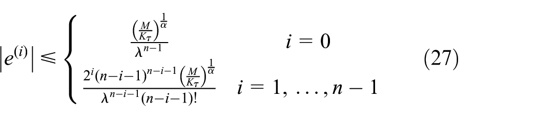
When the control law is a power approach law, the steady-state tracking error bound of the system can be expressed as equation (27):

Then, put
Adaptive super-twisting space decoupling algorithm
Super-twisting sliding mode control is derived from the second-order sliding mode control theory of high-order sliding mode. Its motion trajectory is a super-spiral curve and can reach convergence within a certain time.16–20 Super-twisting can not only maintain the fastness and robustness of first-order sliding mode control but also effectively reduce the chattering generated by the sliding mode observer in vector control and enhance the stability of the system. However, in actual engineering, system boundary conditions are often fluctuated by external interference.21–23 When the system is in the sliding state, the uncertainty and disturbance of the matching are invariant. In order to obtain a good control effect, the switching term gain needs to be adjusted when the system boundary changes, so the adaptive sliding mode algorithm has stronger anti-interference performance.
Control principle of super-twisting algorithm
Compared with the traditional second-order sliding mode control, the super-twisting sliding mode control structure is simple, the required variable information is small, and it is only related to the sliding mode variable.24–26 There is no need to add a new control quantity, and it can be directly applied. Generally, in actual industrial control, the boundary of the system is difficult to determine, so the adaptive super-twisting algorithm should have strong engineering significance. Consider the following controlled system

where
where

In the above formula,
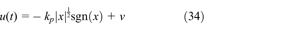
The feedback control function of adaptive Super-twisting sliding mode control can be converted into the following general form as
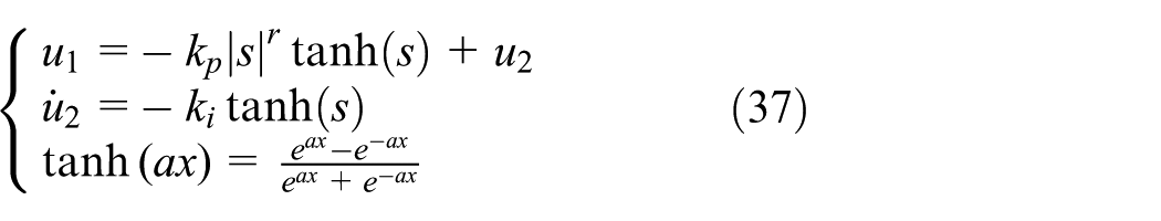
where

Since the hyperbolic tangent function is a continuous and smooth function, the hyperbolic tangent function tanh(x) can be used to reduce the chattering in the second-order sliding mode control using the hyperbolic tangent function tanh(x) instead of the sign function sgn(x), where kp and ki are the parameters that need to be set. In the design of the second-order SMC, it is often only necessary to know the information of the sliding modulus s, and it is not necessary to know the value of the first derivative of s. The controller has two main components. The first one is a nonlinear discontinuous function of the sliding mode variable. The nonlinear variable can be changed by changing the index r. The second term is the integral value of the sliding mode variable, which makes the second order. Sliding mode control can effectively eliminate chattering, and is not affected by parameter changes and external interference, so that the system has strong robustness.
Design of controller based on super-twisting sliding mode algorithm
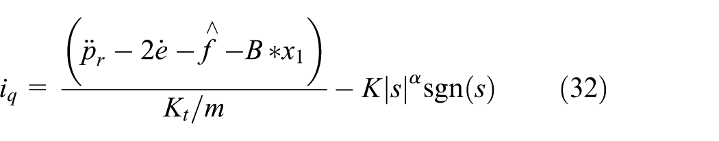
This article designed the second-order sliding mode space based on super-twisting algorithm decoupling controller. According to equations (13)–(18) and (33)–(37), the electromagnetic thrust equation and the three-dimensional contour error equation can be obtained as

Combined with motor dynamics equation

where B, M, τ, Fl, and ψ are all bounded quantities. The necessary and sufficient conditions for finite-time convergence according to equation (24) exist:

Therefore, the second-order SMC based on the super-twisting algorithm can be designed as

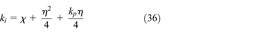
According to formula (35), formula (36) can design the parameters in the speed controller: kp and ki; define
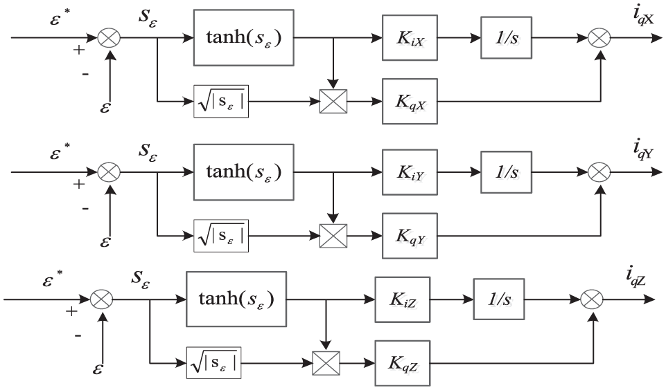
Super-twisting sliding mode controller.
Simulation analysis
The three-axis system in this article is composed of three linear motors, each of which has its own controller. The contour decoupling algorithm controls the contour tracking error to generate the compensation value for the single-axis controller. The combined control signals are output by the combination of the two. In the simulation environment, this article designs three control structures: (1) single-axis proportional–integral–derivative (PID) controller is adopted without space contour compensation. (2) The PID controller is used for the single axis, and the contour error decoupling compensation is performed under the super-twisting controller. (3) The SMC controller is used for the single axis, and the contour error decoupling compensation is performed under the super-twisting controller.
In the simulation results, as shown in Figure 6, under the control of the contour error decoupling algorithm, the system’s tracking effect on spatial spiral is better than that under the deconstruction algorithm without contour error decoupling algorithm. It can be found from the partial enlargement of Figure 6 that due to the strong convergence characteristic of the sliding mode control structure, a fast switching motion is performed around a given trajectory contour under the control of the sliding surface, thereby approaching a given trajectory. And, under the same super-twisting decoupling controller, the final contour tracking effect is better than the PID control structure. In Figure 7, by comparing the three-axis total contour error under different control structures, it can be found that under the control of the space decoupling controller gain compensation, the spatial contour error of the system is significantly reduced, based on the super-twisting decoupling controller. The tracking error of the sliding mode control structure is smaller, the response speed is faster, and the control precision reaches 30 µm. In order to better analyze the tracking ability of the system for a given space trajectory, the space contour error when the given contour is a spiral is projected to the XY plane to obtain Figure 8, and the error curve can be obtained from the three axes based on the SMC. Under the linear motor decoupling control strategy, the convergence of the system is obviously enhanced, and the error convergence process is smooth and approximately perfect, indicating that the system is more stable. In order to further verify the anti-interference ability of the three-axis system, step disturbances are suddenly added at 12 S in the simulation test. For example, Figure 9 shows that the three-axis system based on the PID control structure produces a significant abrupt change to the disturbance signal, resulting in a larger contour error; after a certain adjustment time, the system error is stabilized. The three-axis system based on the sliding mode control structure produces small fluctuations to the disturbance signal and recovers quickly, without a large spatial contour error. Therefore, the linear motor three-axis system based on sliding mode control has strong anti-interference ability.

Given contour and actual tracking curve.

Contour error under different structures.

Contour error in XY plane projection.

Space contour error map after loading.
Experimental study based on three-axis linear motor platform
In this section, the space contour tracking experiments are carried out under no-load and rated load conditions, respectively, and the effectiveness of the spatial decoupling control strategy of the three-axis linear motor based on SMC is verified. It is proved that the algorithm can effectively reduce the contour error and improve the running precision of the three-axis linear motor platform. The experimental device is mainly composed of precision XYZ three-axis precision linear motor platform, ACJ-005-09 Copley Servo Driver (Akribis company, headquartered in Singapore), the Galil DMC Control Card (Galil company, USA), VILT - 0400 Grating Sensor (JK Laser company, USA). The experimental platform is shown in Figure 10, and its main attribute parameters are shown in Table 1.

Triaxial motion experimental device.
Main parameters of permanent magnet synchronous linear motor.

The three-axis linear motor experimental platform performs the space spiral trajectory tracking task. Under the control of the spatial decoupling control algorithm of the three-axis linear motor based on sliding mode control, the space contour can be effectively tracked, in order to better represent under the control of the algorithm. The tracking ability of the actual trajectory for a given trajectory is, respectively, performed as an XY projection map and a YZ projection map for the spatial spiral tracking condition, as shown by Figures 11 and 12, respectively.

XY projection.
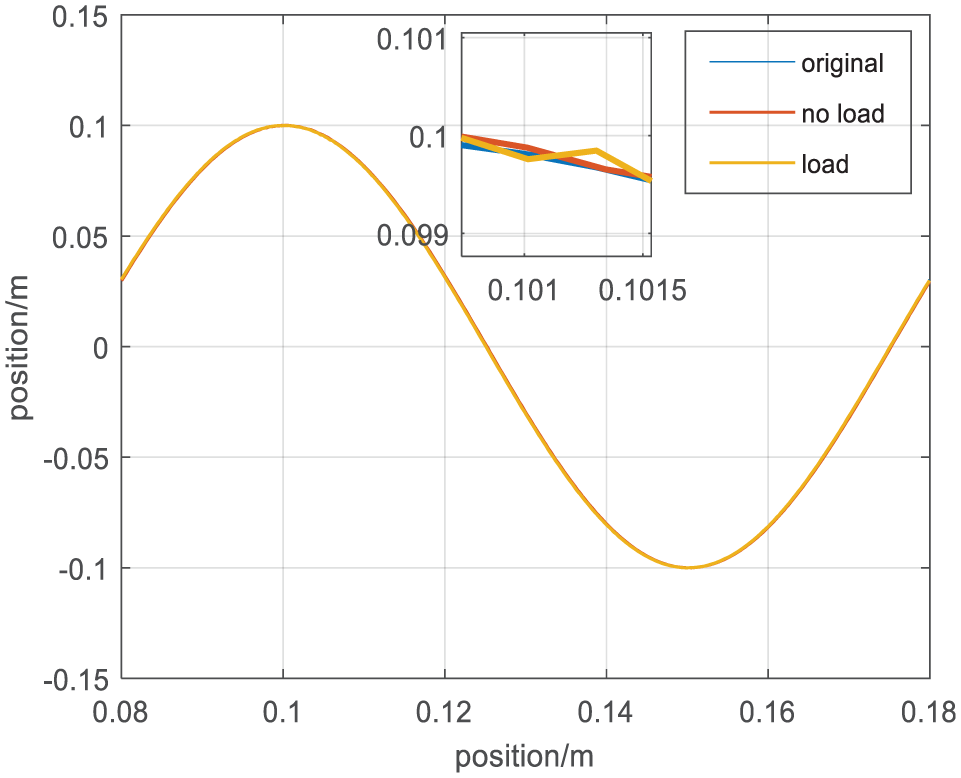
YZ projection.
It can be seen from Figures 11 and 12 that the three-axis linear motor system can better track a given space contour curve. In the partial enlargement diagram, it can be found that the tracking curve under no-load is as close as possible to the given task position curve. Under the rated load, the actual position curve has a small chattering, indicating that the system has strong anti-interference ability. It can be seen from Figures 13 and 14 that the average spatial contour error under no-load conditions is less than 5 µm, and the average contour error is less than 15 μm after the rated load is added, thus demonstrating the effectiveness of the control algorithm. The three-axis system based on the SMC-based three-axis linear motor space decoupling control algorithm has high running precision and strong anti-interference ability.

Space contour error without load.

Spatial contour error under load.
Conclusion
In order to reduce the tracking error of the three-axis motion system on the space contour curve, this article establishes a contour error model based on the three-axis system. By getting the uniaxial position error and the given position signal at a certain moment, the approximate value of the space contour error can be obtained. The method has strong operability, small calculation amount, and easy engineering realization. In this article, the adaptive super-twisting SMC is designed to reduce the contour error of the whole system, give the compensation gain of each axis during the motion, and can follow the boundary change caused by the disturbance and dynamically adjust the controller parameters. And, with each single-axis SMC, correct each control input to achieve high-precision space contour tracking tasks. The simulation experiment and the experiment based on the three-axis linear motor platform prove that the space decoupling algorithm can effectively reduce the spatial contour error of the three-axis system. The system has higher precision under the control of the sliding mode structure and external load disturbance. Moreover, it is also relatively stable.
Footnotes
Handling Editor: Hamid Reza Karimi
Declaration of conflicting interests
The author(s) declared no potential conflicts of interest with respect to the research, authorship, and/or publication of this article.
Funding
The author(s) disclosed receipt of the following financial support for the research, authorship, and/or publication of this article: This work was supported by the National Natural Science Foundation of China (51637001, 51577048, and 51877070), Hebei Provincial Natural Science Foundation Project (E2018208155), Hebei Province Overseas Students Science and Technology Activity Project Selected Project (C2015003044), Hebei Province Higher Education Science and Technology Research Key Project (ZD2018228), High-Energy-Saving Motor and Control Technology National and Local Joint Engineering Laboratory Open Project (KFKT201804), and Hebei Province Graduate Innovation Funding Project (CXZZSS2018085).