
Abstract
The precision equipment bears the vibration excited by the road roughness during transportation, and faces the risk of damage arising from the vibration. The parallel air spring vibration isolation system (PAVS) has an excellent vibration isolation performance, so has a good application prospect in the precision equipment transportation. But under the conditions of abnormal road and eccentric load, PAVS bears great vibration excitation, and the resulting large deformation of air spring makes the air spring stiffness nonlinear, so to obtain an excellent vibration isolation performance faces a great challenge. Aiming at this problem, based on the measured parameters, the nonlinear dynamics model of PAVS is proposed. Then, the influence of air spring under large deformation on the vibration isolation characteristics is discussed. Finally, under the condition of eccentricity of precision equipment, the vibration isolation characteristics of PAVS with equal height control strategy is investigated. The results show that PAVS with the equal height control strategy has good vibration isolation characteristics. So for the transportation of large precision equipment, PAVS is a potentially useful method.
Keywords
Introduction
When satellite, medical instrument, and other precision equipment are transported, the vibration is inevitable. The mechanical systems bear such detrimental vibrations and the precision equipment may even be damaged.1–3 Therefore, it is necessary to reduce the vibration of precision equipment carried on vehicle during transportation. At present, because of the good adaptability and excellent reliability of the vibration isolation system using various spring and damping elements, it is a popular method of vibration isolation.
The wire rope spring can serve as spring and damping simultaneously, so it may simplify and condense the vibration isolation system. The advantage makes wire rope spring widely used. 4 Chaudhuri and Kushwaha. 5 designed a fixture assembly supported on several wire rope isolators for heavy extra-long cargo vibration isolation during transportation. Yao et al. 6 presented a novel isolator system consisting of MR damper and wire rope in parallel to control the isolator mechanics characteristics and deal with the problem of low frequency vibration reduction and high frequency impact resistance of ship equipment. Zhang et al. 7 applied wire rope vibration isolators to reduce the airborne optical system vibration. An important characteristic of wire rope isolators is that it has the ability to isolate vibration in all directions, so it can be used in any direction to safeguard the structure and equipment.8–10 However, it is difficult to satisfy various requirements of vibration isolation by adjusting the parameters of wire rope isolator.
In order to overcome the wire rope isolator disadvantages and obtain a better vibration isolation effect, a parallel air spring vibration isolation system (PAVS) used to transporting precision equipment is proposed in our previous work. 11 The system is of simple structure, good lateral stability, and excellent vibration isolation performance. At present, in the field of vibration isolation, the air spring has been extensively studied. These researches mainly focus on the air suspension of vehicle and train. Li et al. 12 studied the performance of torsion elimination or the interconnection form influences the interconnecting effectiveness of an interconnected air suspension. The air spring was assumed to be an adiabatic system in the dynamic simulation model. To correctly reproduce the air spring nonlinear characteristics, Zhu et al. 13 advanced an air spring mechanical model. Docquier et al. 14 considered multibody and pneumatic aspects simultaneously to model the train’s pneumatic suspension with a multidisciplinary approach. Chang and Lu 15 investigated the air spring suspension dynamic behavior by using an air spring dynamic model, where the heat transfer process is included and integrated into the vehicle dynamics model. Qi et al. 16 established a dynamics model of high-speed EMU train air spring which is three-dimensional coupled by using the thermodynamics equations derivation and a curve-fitting method. Abid et al. 17 proved that the GENSIS air spring suspension system has an equal characteristic as the passive suspension system. Kang 18 established the high-speed train models as the air suspension characteristics are the nominal values under normal conditions. Nakajima et al. 19 advanced an air suspension system nonlinear model based on the thermodynamic approach, which can be integrated into multipurpose multibody dynamics computer algorithms. Zheng et al. 20 presented a vehicle use air suspension simulation model with auxiliary chamber in AMEsim based on the air suspension mechanic model. In addition, there are other areas of applied research, such as the wheeled tractor with suspended driver seat, 21 ultra-precision manufacturing engineering, 22 bridges, 23 maglev levitation system, 24 and marine propulsion unit. 25
From above research, it can be concluded that air springs are mainly used in the vibration isolation system working in a single working condition, without considering the influence of the change of working conditions on the vibration isolation effect. However, during transportation, the vibration isolation system will face different conditions, such as poor road or eccentric load conditions in practical application. Therefore, the influence of these conditions on the system needs to be studied. In this paper, the influence of different conditions on the vibration isolation performance of PAVS has been investigated. Firstly, the air spring dynamics model is established by using a simple method, the curve-fitting of experimental data.16,26,27 Then, the simulation results calculated from the nonlinear model are compared with those from the linear model and the influence of the nonlinearity of air spring stiffness is analyzed. Finally, the eccentricity case is simulated with the nonlinear model.
The remainder of this paper proceeds as follows. In Section 2, the nonlinear dynamic model of PAVS is established. In Section 3, the influence of the nonlinearity of air spring stiffness is discussed. In Section 4, for the case of the eccentricity, the simulation of the nonlinear model with the equal height control strategy is performed. Finally, in Section5, the conclusions are drawn.
Dynamic model of parallel air spring damping system introducing the nonlinear air spring stiffness
The working height, internal pressure, and other factors will influence the air spring stiffness, and the stiffness is nonlinear in the whole working stroke. For the case of small deformation of air spring under good road condition, the linearity assumption of air spring stiffness is feasible and the accuracy of simulation results is acceptable. But for the case of large deformation of air spring under severe road condition, the linearity assumption of air spring stiffness will cause obvious deviations in the simulation results.
Air spring stiffness test under large stroke
In this system, the air spring of double-bellows type (ContiTech FD110-15) is applied. A series of static vertical stiffness tests are performed to obtain the nonlinearity characteristics of air spring stiffness. The experimental setup of large stroke vertical stiffness test is illustrated in Figure 1.
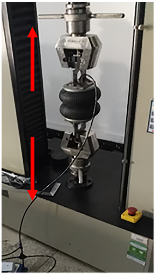
Experimental setup of large stroke vertical stiffness test.
The load-displacement curves of air spring under large stroke is measured and plotted in Figure 2. During the test, the air mass in air spring is constant. The test stroke is from 12 to 19 cm, which is the air spring working height range. The stiffness curves (the slope of the curves in Figure 2) are calculated and shown in Figure 3. It can be seen that in the whole working stroke, the vertical stiffness is nonlinear. According to the stiffness characteristics of different initial air pressure, it can be concluded that although there exist different values of air spring stiffness for different initial air pressures, the stiffness curves are very similar and the minimum stiffness appears at the height of about 18 cm.
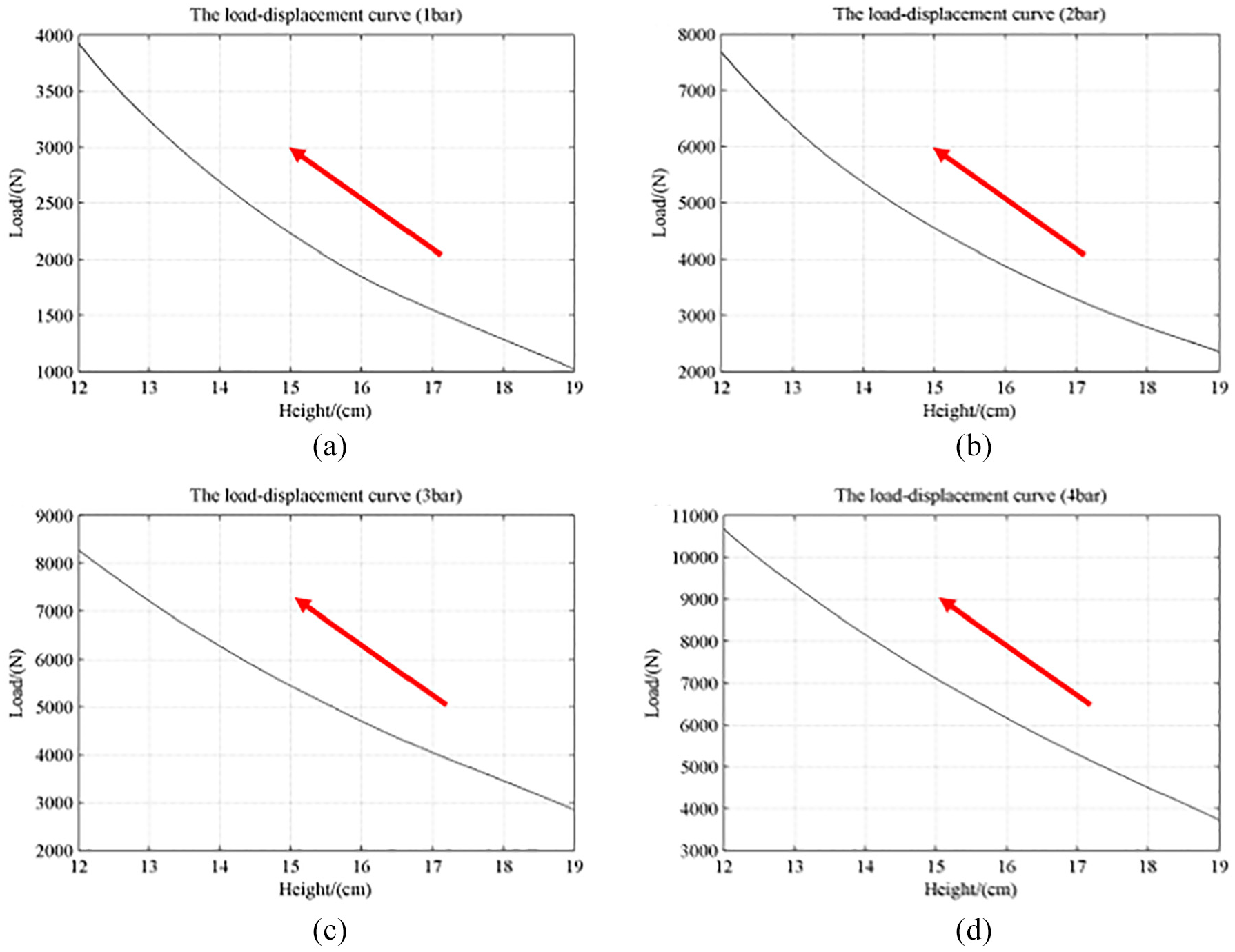
Load-displacement curves: (a) initial air pressure of 1 bar, (b) initial air pressure of 2 bar, (c) initial air pressure of 3 bar, and (d) initial air pressure of 4 bar.
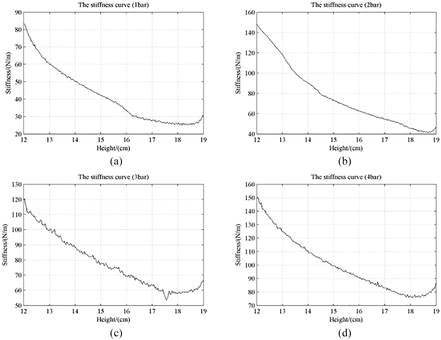
Stiffness curves: (a) initial air pressure of 1 bar, (b) initial air pressure of 2 bar, (c) initial air pressure of 3 bar, and (d) initial air pressure of 4 bar.
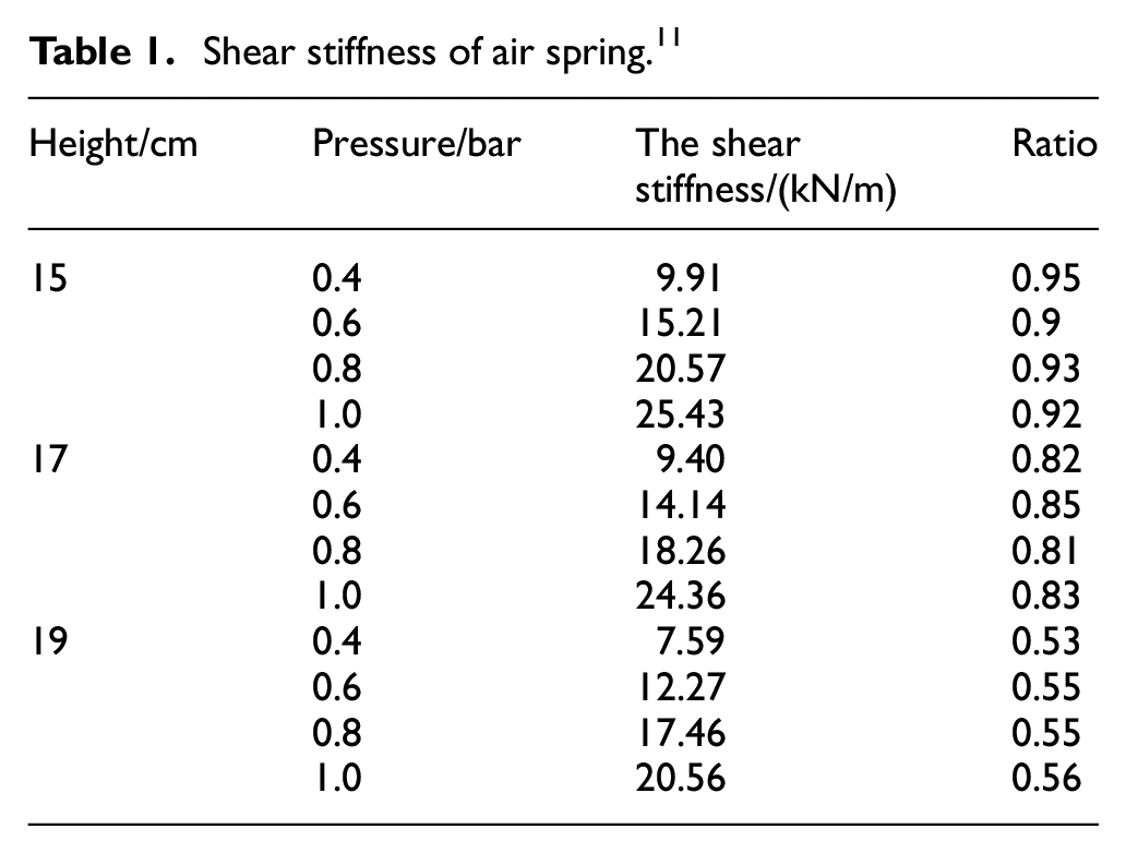
Generally, during transportation the air spring has a small lateral vibration amplitude of (less than 1 cm), so the shear stiffness near the same working height can be approximated as a constant. The shear stiffness of air spring under different working heights is listed in Table 1 (from the authors’ previous paper 11 ), where the ratio is of the shear stiffness to the vertical stiffness. It can be concluded that both the working height and the initial air pressure affect the air spring shear stiffness. Although internal air pressures are different, the ratios of the shear stiffness to the vertical stiffness are very close under the same working height.
Shear stiffness of air spring. 11
Nonlinear dynamic model
The structure of the system 11 in SolidWorks is shown in Figure 4. The adapter plate are supported by four air springs and two dampers on the bottom plate. The total weight of the platform, made of aluminum alloy, is 145.7 kg. The rigid-body dynamic model is created in Adams as demonstrated in Figure 5. The air spring is replaced by the force in three directions in Adams, and the forces in three directions can be expressed as the quantity nonlinearly related to the displacement. The torques in three directions are ignored. By processing experimental results in Section 2.1, the air spring stiffness parameters can be obtained. In Adams, the damper can be regarded as a “translational spring damper” component. The x, y, and z directions are along the driving direction of the vehicle, the lateral direction, and the vertical direction, respectively.
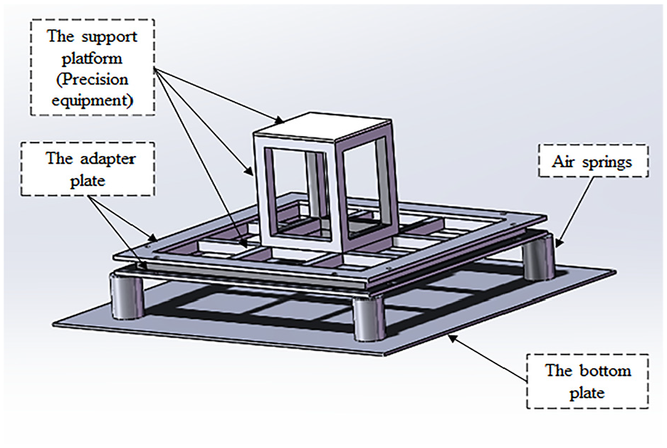
Structure of PAVS. 11
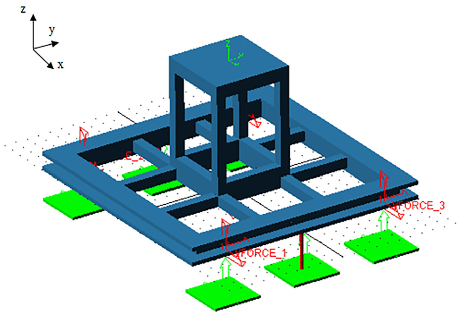
Nonlinear rigid body dynamic model of PAVS.
According to the experimental data in Section 2.1, the nonlinear relations of air spring stiffness can be achieved. The vertical loads of air spring corresponding to any initial air pressure (0–4 bar) and working height (12–19 cm) are obtained by using two-dimensional interpolation of the experimental data shown in Figure 2. Through the load analysis of the dynamic model, at a certain working height, each air spring’s load can be achieved. According to the data obtained by above interpolation, the vertical load-displacement relation of air spring can be obtained. Then the shear stiffness-displacement relation can be obtained by the vertical stiffness and the ratio of the shear stiffness to the vertical stiffness. By introducing the vertical load-displacement relation and the shear stiffness-displacement relation of air spring into Adams, the nonlinear dynamic model is established. The establishment process is shown in Figure 6.
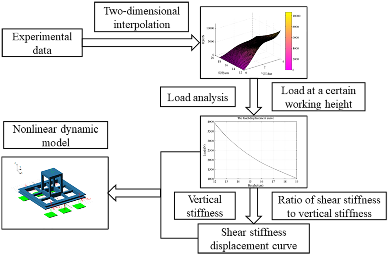
Establishment process of the nonlinear dynamic model.
During the actual transportation, the vibration acceleration of the vehicle floor under typical road conditions are collected. And the vibration acceleration used as the excitation is applied to the floor in Adams. The center point of the support platform is considered to be the response location. The precision equipment is of 6 DOFs, and the vibration isolation effect is evaluated by the root-mean-square (RMS) of the vertical acceleration, the maximum vertical acceleration, and the maximum displacement in three directions at the center point. Moreover, the transmissibility of vibration isolation including the transmissibility of RMS of acceleration and the transmissibility of the maximum acceleration is introduced to evaluate the vibration isolation effect.
Influence of key parameters on dynamic response characteristics
Influence of the working height
In Section 2.1, the air spring test results indicate that the air spring stiffness is nonlinear in the whole working stroke. Therefore, the influence of the linearity assumption of air spring stiffness for different working heights is definitely various.
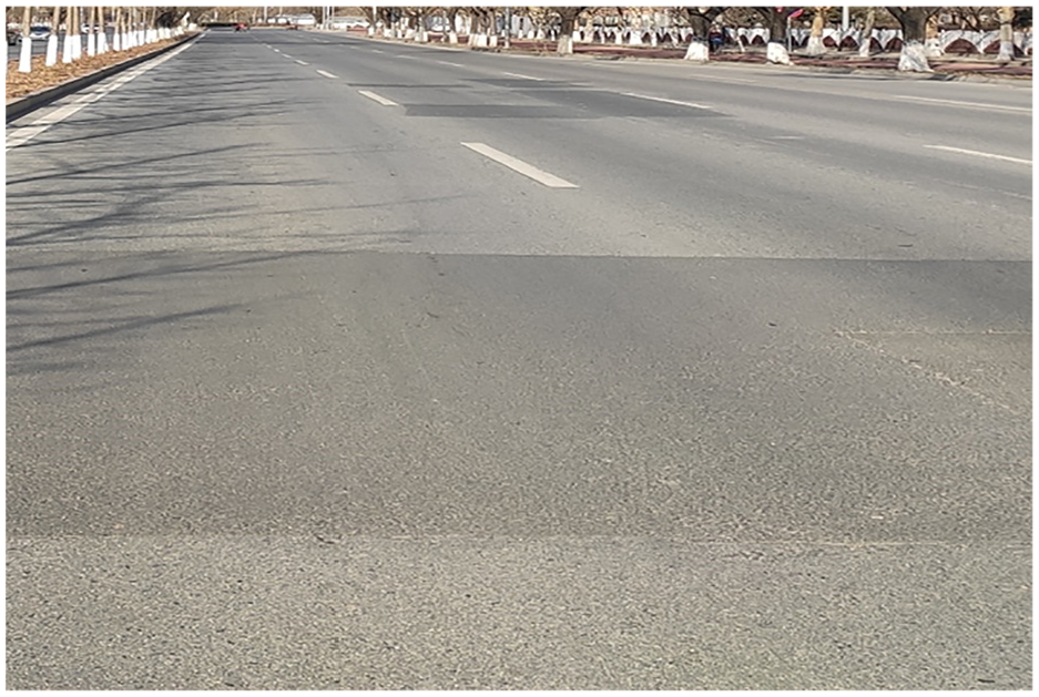
Normal road condition
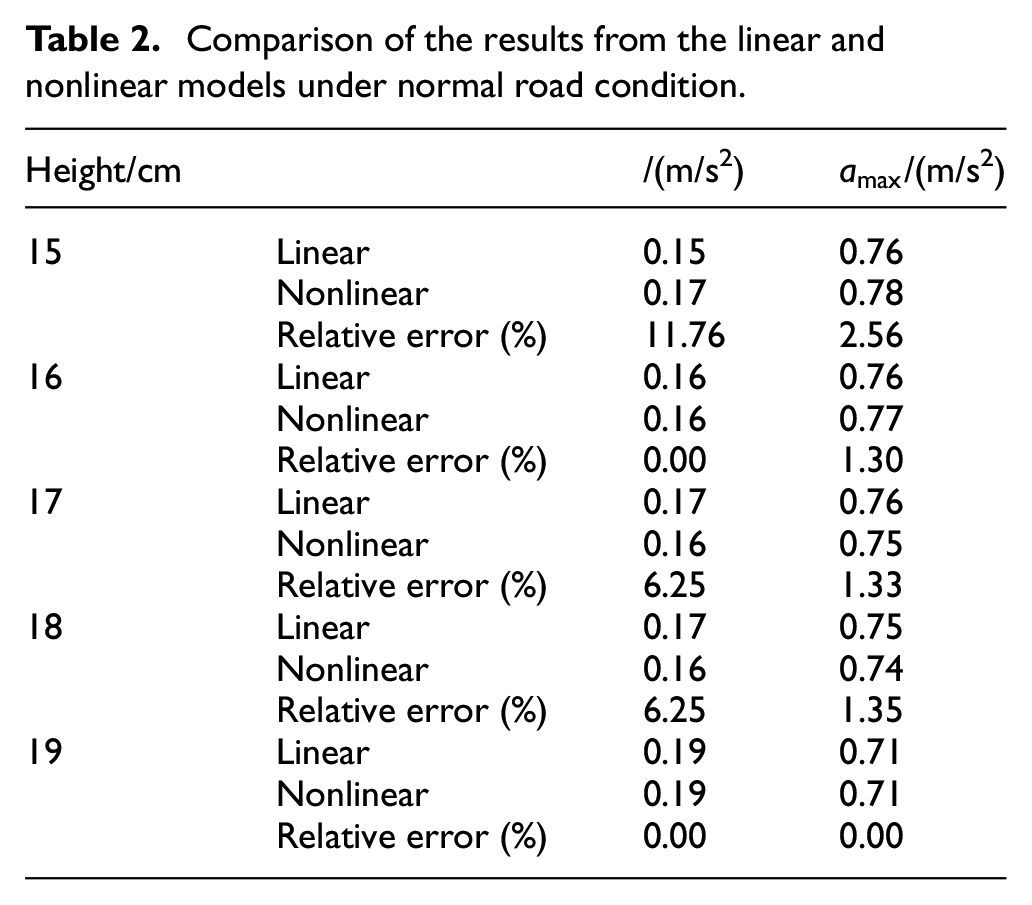
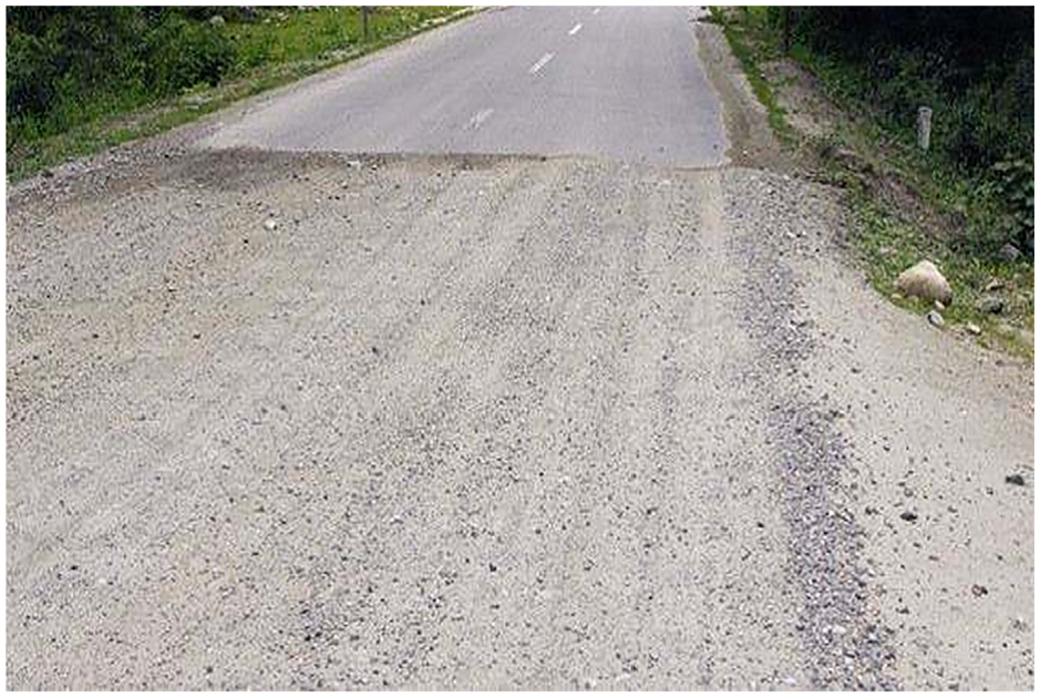
Normal road condition is relatively stable with fewer bumps, as shown in Figure 7. The measured excitation obtained during the transportation under normal road condition is used as the input of the model. The RMS acceleration of the excitation is about 0.3486 m/s2, and the maximum acceleration of the excitation is 1.9281 m/s2. For different air spring working heights of 15–19 cm, the vibration responses from the dynamic model with the linearity assumption of air spring stiffness and one with the nonlinear air spring stiffness are calculated and compared, respectively. In simulation, the damping ratio of the system is set as a constant (0.4). The results are shown in Table 2. The relative error is calculated based on the result of the nonlinear model. Zhu et al.
13
compared vertical frequency-weighted RMS acceleration values from the proposed model, the Berg’s model, and ride test results. The proposed model error is within 10%, while the Berg’s model error is over 10%. It is shown that results from the vehicle with the proposed model match the experimental data more closely than those from the vehicle with the Berg’s model. Qi et al.
16
compared the vertical stiffness and damping results of the calculation and experiment. The relative error within 10% was considered to satisfy the requirements of engineering calculations. Mazzola and Berg
28
discussed and assessed six models for the air spring secondary suspension based on comparison with experiments. The difference within 10% between the maximum and minimum force of the experiments and models means slight. Therefore, the benchmark of the relative error in this paper is chosen to be 10%, which satisfies the requirements of engineering calculations. If the relative error is greater than 10%, it is considered that the difference between the linear mod
Normal road condition.
Comparison of the results from the linear and nonlinear models under normal road condition.
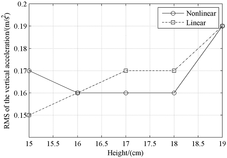
Change of RMS of the vertical acceleration with the working height.
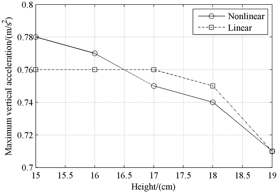
Change of the maximum vertical acceleration with the working height.
From Table 2 and Figures 8 and 9, we can see that the relative errors between the results of the linear and nonlinear models is within 6.25% for the working height of 16–19 cm, which indicates that the linearity assumption of the model is reasonable. For the working height of 15 cm, the relative error goes up to 10%. So under this situation, the linearity assumption will cause a greater error. As can be seen from Figure 3, the stiffness of the air spring is different at different heights. The simplified linear stiffness is different from the actual air spring stiffness. This will cause different amplitudes of the system during vibration isolation. Therefore, the influence of nonlinearity on the vibration isolation effect is varied with the working height, and the nonlinearity of the spring sometimes has a beneficial effect on vibration isolation.
As is well known, compared with RMS of acceleration, the precision equipment is more likely to be damaged because of the maximum acceleration. Therefore, in the vibration isolation system design, reducing the maximum acceleration by adjusting parameters is preferred. In accordance with the results from the nonlinear model, the vibration isolation effect is best when the working height of air spring is 19 cm.
Abnormal road condition
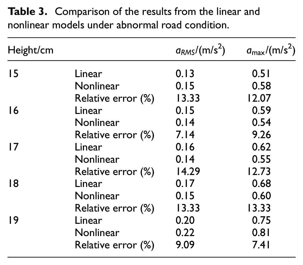
During transportation, the vehicle carrying precision equipment may pass through the gravel road (Figure 10). The deformation of air spring will increase obviously, and the vibration isolation requirements of the system face a greater challenge. For this case, the dynamic characteristics of PAVS and the influence of the working height will be studied in this section. The vertical acceleration excitations measured on a specific vehicle running on this abnormal road during transportation are used as the input of the model. The RMS acceleration of the excitation is 0.8279 m/s2, and the maximum acceleration of the excitation is 3.3337 m/s2. The damping ratio is set as a constant (0.4). For different air spring working heights of 15–19 cm, the vibration responses from the linear model and the nonlinear model are calculated and compared, respectively. The results are shown in Table 3. The change of RMS of the vertical acceleration with the working height and the change of the maximum vertical acceleration with the working height are illustrated in Figures 11 and 12, respectively.
Abnormal road condition.
Comparison of the results from the linear and nonlinear models under abnormal road condition.
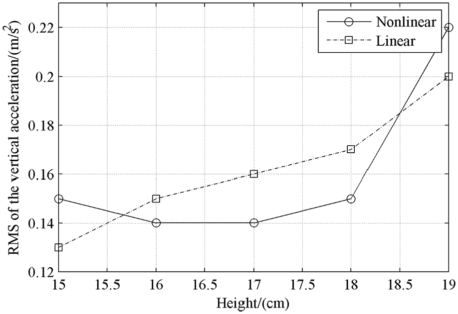
Change of RMS of the vertical acceleration with the working height.
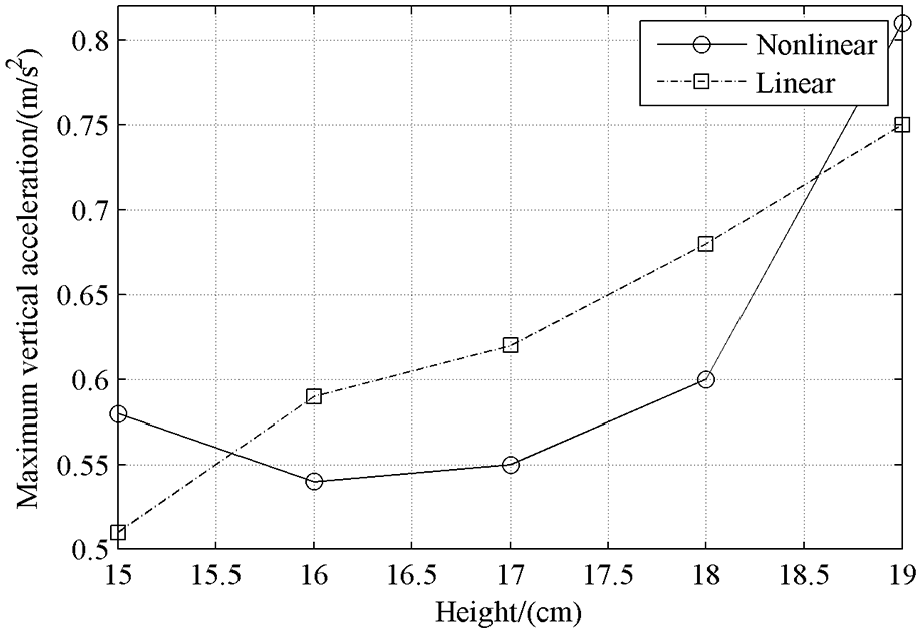
Change of the maximum vertical acceleration with the working height.
From Table 3 and Figures 11 and 12, we can see that for the working height of 15, 17, and 18 cm, the relative errors between the results from the linear and nonlinear models are up to 14.29%. Obviously, the linearity assumption has caused the greater error, and is not applicable for this case. Moreover, the influence of nonlinearity on the vibration isolation effect is varied with the working height. At the same working height, the relative error between simulation results from the linear model and the nonlinear model under abnormal road condition is always bigger than that under normal road condition. It is because that the deformation of air spring and the nonlinearity of its stiffness under abnormal road condition are greater than those under normal road condition. Therefore, for abnormal road condition, the nonlinearity of air spring stiffness should not be ignored.
In accordance with the simulation results from the nonlinear model, the vibration isolation effect is best when the working height of air spring is 16 cm.
Influence of the damping ratio
During transportation, the damping affects the amplitude of the system, resulting in the variation of air spring heights. Therefore, the influence of damping ratio on the vibration isolation characteristics needs to be studied. Base on the results, the appropriate damping ratio can be determined to obtain better vibration isolation performance.
Normal road condition
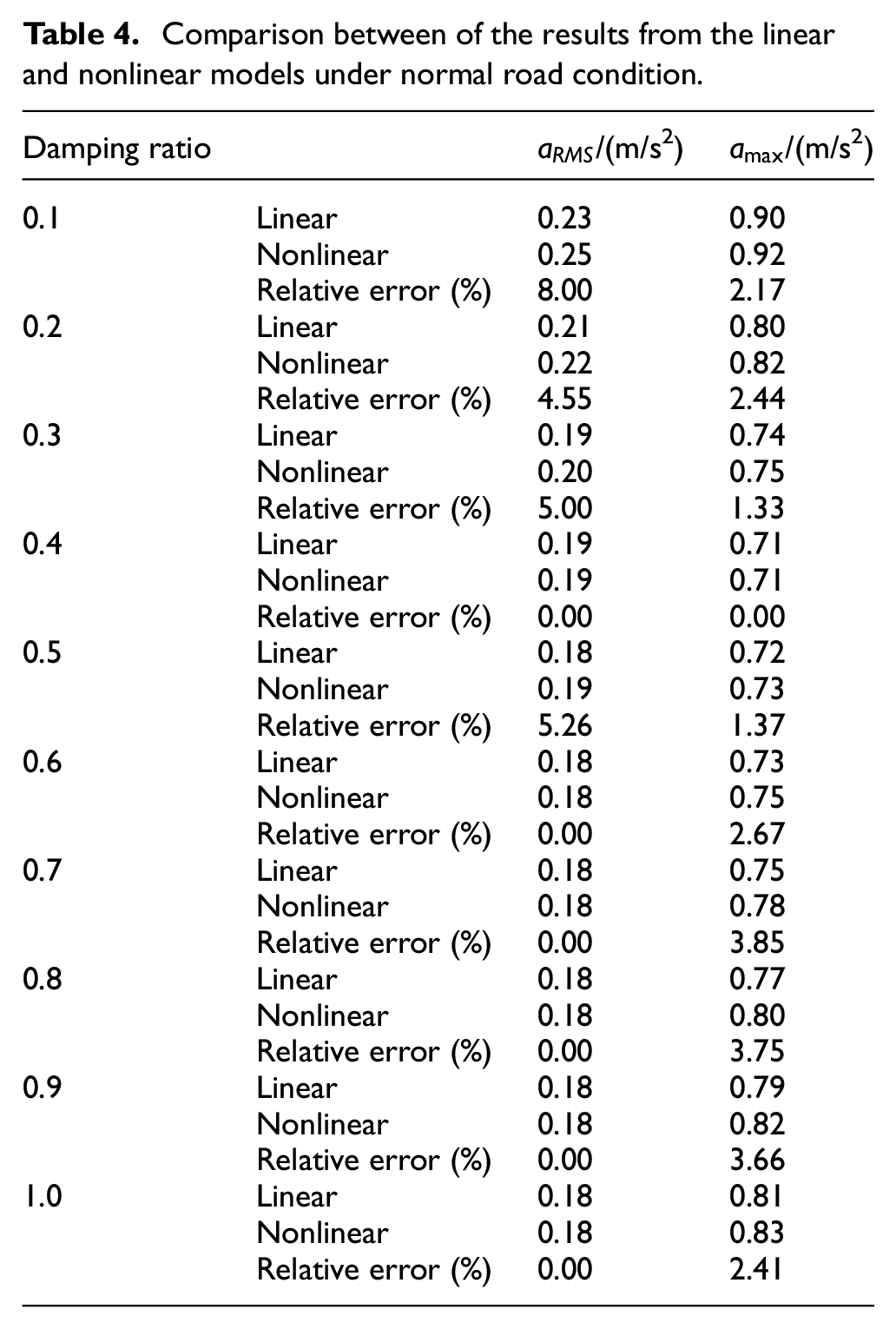
The acceleration excitation measured during transportation under the normal road condition is used as the input of the model. In accordance with the simulation results in Section 3.1.1, at the air spring working height of 19 cm, the vibration isolation effect is best. Therefore, all models are simulated at the height of 19 cm here. The vibration responses from the linear dynamic model and the nonlinear dynamic model are calculated and compared respectively for the different damping ratios. The results are shown in Table 4. The change of RMS of the vertical acceleration with the damping ratio and the change of the maximum vertical acceleration with the damping ratio are illustrated in Figures 13 and 14, respectively.
Comparison between of the results from the linear and nonlinear models under normal road condition.
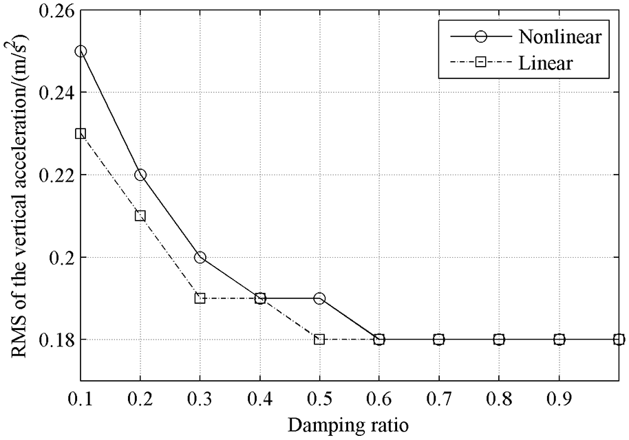
Change of RMS of the vertical acceleration with the damping ratio.
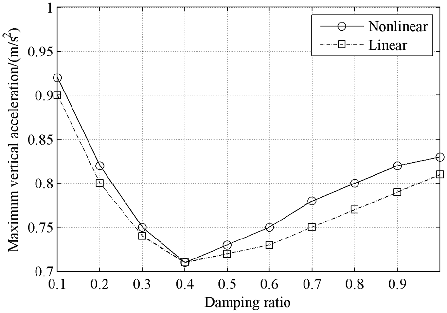
Change of the maximum vertical acceleration with the damping ratio.
From Table 4 and Figures 13 and 14, it can be seen that the relative errors between the results of linear and nonlinear models are within 8.00%. It is indicated that under normal road conditions, the influence of nonlinearity of air spring stiffness is relative weak, and the linearity assumption of air spring stiffness is acceptable.
In accordance with the results from the nonlinear model with damping, RMS of the vertical acceleration decreases with the increase of damping ratio, but for the maximum vertical acceleration, a different rule appears. The best vibration isolation effect is reached when the damping ratio is 0.4.
In conclusion, in accordance with the results under normal road condition, when the working height of air spring is 19 cm and the damping ratio is 0.4, the best vibration isolation effect may be obtained.
Abnormal road condition
The acceleration excitation measured during transportation under the abnormal road condition is used as the input of the model. In accordance with the simulation results in Section 3.1.2, at the air spring working height of 16 cm, the vibration isolation effect is best. Therefore, all models are simulated at the height of 16 cm here. The vibration responses from linear dynamic model and nonlinear dynamic model are calculated and compared respectively for different damping ratios. The results are shown in Table 5. The change of RMS of the vertical acceleration with the damping ratio and the change of the maximum vertical acceleration with the damping ratio are illustrated in Figures 15 and 16, respectively.
Comparison between of the results from the linear and nonlinear models under abnormal road condition.

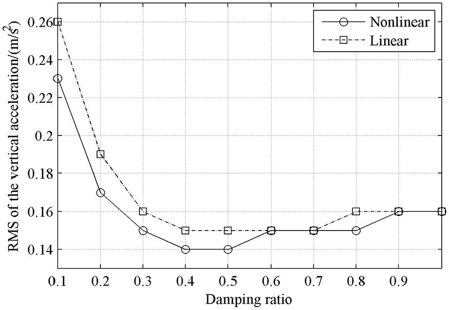
Change of RMS of the vertical acceleration with the damping ratio.
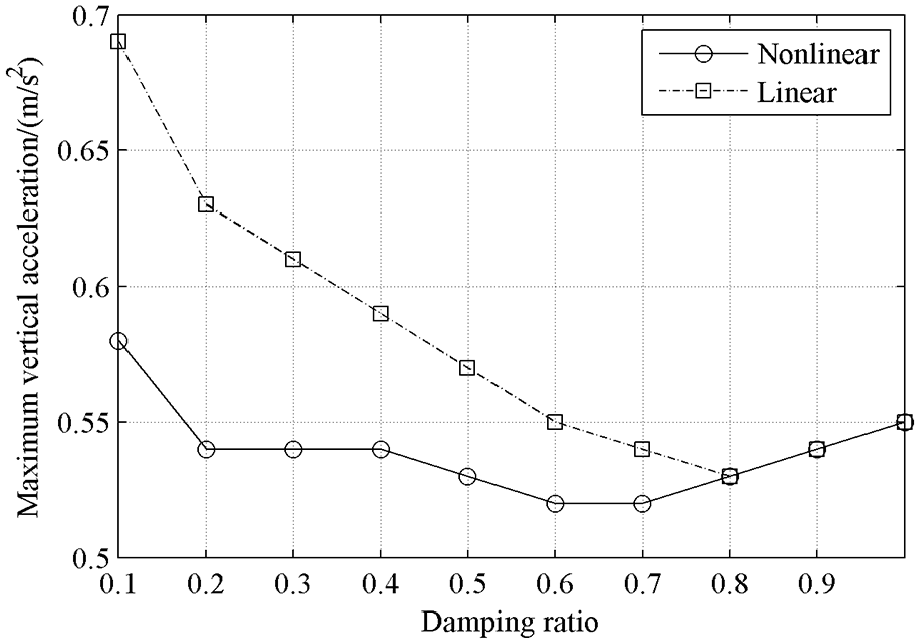
Change of the maximum vertical acceleration with the damping ratio.
As can be seen from Table 5 and Figures 15 and 16, when the damping ratio is 0.1–0.3, the relative errors between the results from the linear and nonlinear models go up to 18.97%. Obviously, the linearity assumption has caused the greater error, and is not applicable for this case. But for the damping ratio of 0.4–1.0, the relative errors between the results from the linear and nonlinear models are within 10%, which is relatively small. It is indicated that for this case, the influence of nonlinearity of air spring stiffness is relative weak, and the linearity assumption of air spring stiffness is acceptable.
With the damping ratio increasing, the vibration amplitude of the system is reduced and the air spring deformation decreases. This leads to the nonlinearity of air spring stiffness and the influence of the nonlinearity on the system being weak.
According to the results from the nonlinear model with damping, RMS of the vertical acceleration does not always decrease when the damping ratio increases, and the maximum vertical acceleration also does not always decrease when the damping ratio increases. For the damping ratio of 0.6–0.7, the best vibration isolation effect is reached.
In conclusion, in accordance with the results under abnormal road condition, when the working height of air spring is 16 cm and the damping ratio is 0.6 and 0.7, the best vibration isolation effect may be obtained. Because the input excitations contain various frequency components and have large amplitude at different frequencies, the influence of the working height of the air spring and the damping on the vibration isolation effect is very complicated and has any specific trend. Therefore, the air spring stiffness and the damping are necessary to be adjusted based on the road conditions to obtain a positive vibration isolation effect.
Vibration isolation effect analysis
According to the results of Sections 3.1 and 3.2, under normal road condition, the vibration isolation effect is the best when the working height is 19 cm and the damping ratio is 0.4. And under abnormal road condition, the vibration isolation effect is best when the working height is 16 cm and the damping ratio is 0.6 and 0.7. In order to further study the corresponding vibration isolation effect, the transmissibility of vibration isolation is introduced under the optimal parameters, such as the transmissibility of the acceleration RMS and the maximum acceleration. The transmissibility of the acceleration RMS is given by
where
where
Normal road condition
The nonlinear model is simulated at a working height of 19 cm and a damping ratio of 0.4. The acceleration RMS of the response is 0.19 m/s2.The maximum acceleration of the response is 0.71 m/s2.Therefore, the transmissibility of the acceleration RMS is 54.5% and the transmissibility of the maximum acceleration is 36.8%. It indicates that the vibration isolation system has good vibration isolation effect.
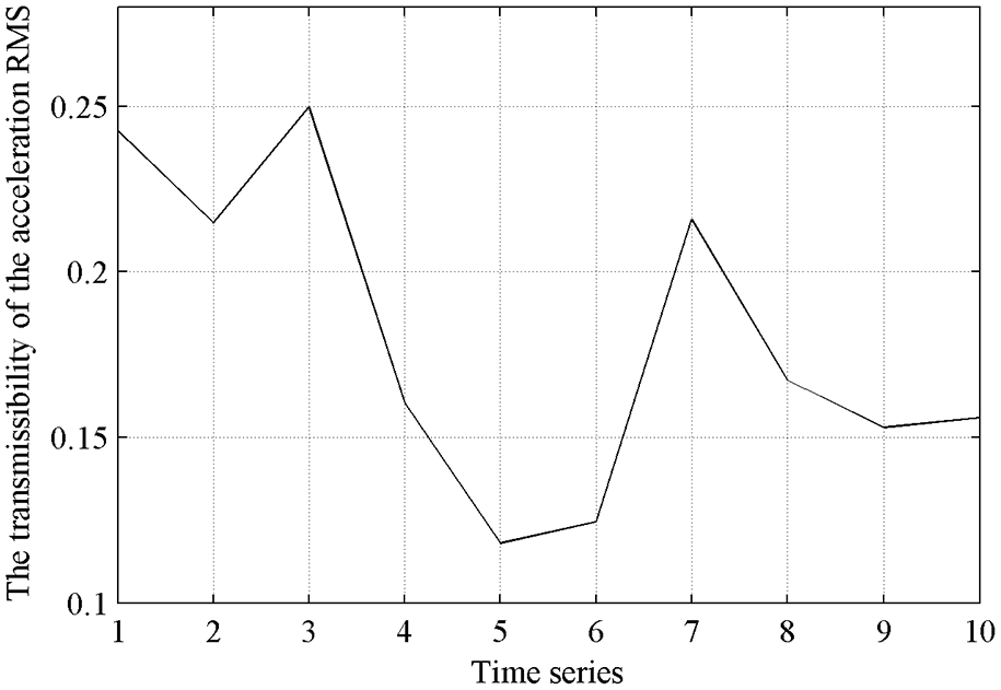
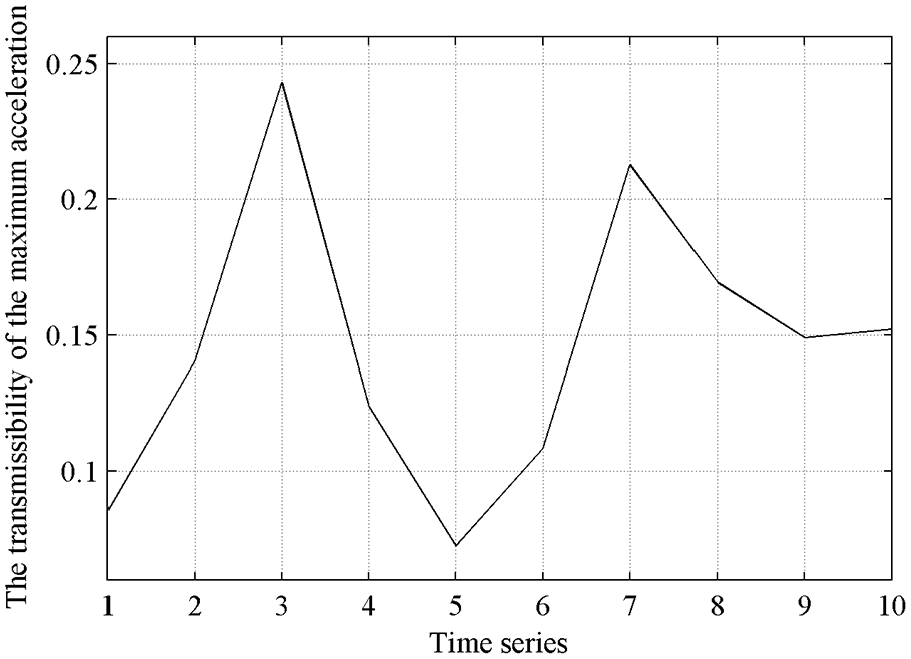
The time length of the normal road condition signal is 80 s. The input excitation and output response are analyzed in the time domain with each second as a time series. The transmissibility of the acceleration RMS and the maximum acceleration in each second are shown in Figures 17 and 18, respectively. It can be seen from Figures 17 and 18, the transmissibility of the acceleration RMS is basically less than 1 and the transmissibility of the maximum acceleration is always less than 1. It indicates that the vibration isolation system has a good vibration isolation effect in the whole time period under normal road condition.
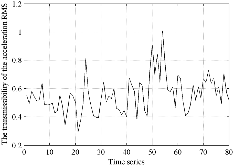
The transmissibility of the acceleration RMS under normal road condition.
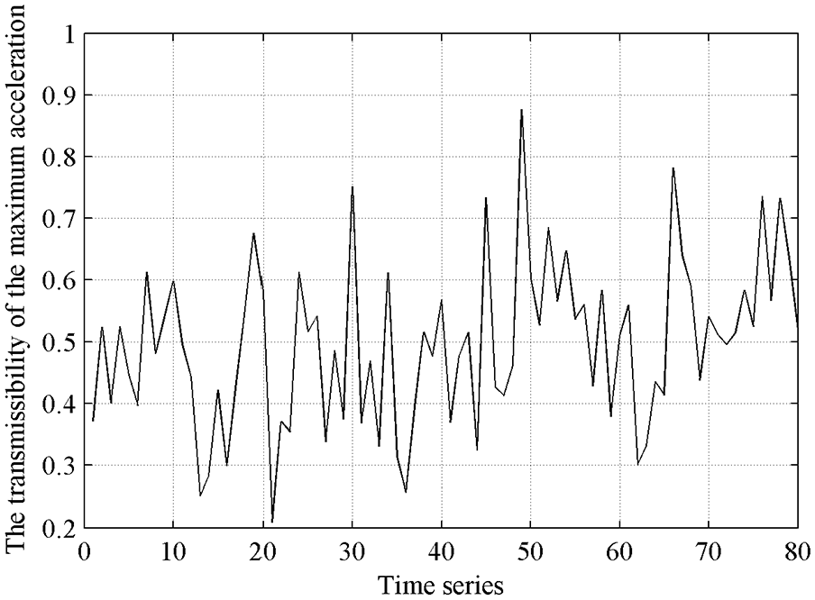
The transmissibility of the maximum acceleration under normal road condition.
Abnormal road condition
The nonlinear model is simulated at a working height of 16 cm and a damping ratio of 0.6. The acceleration RMS of the response is 0.15 m/s2.The maximum acceleration of the response is 0.52 m/s2.Therefore, the transmissibility of the acceleration RMS is 18.1% and the transmissibility of the maximum acceleration is 15.6%. It indicates that the vibration isolation system has good vibration isolation effect.
The time length of the normal road condition signal is 10 s. The input excitation and output response are analyzed in the time domain with each second as a time series. The transmissibility of the acceleration RMS and the maximum acceleration in each second are shown in Figures 19 and 20, respectively. .It can be seen from Figures 20 and 21 that even under abnormal road condition, the transmissibility of the acceleration RMS and the maximum acceleration are always less than 0.3.
The transmissibility of the acceleration RMS under abnormal road condition.
The transmissibility of the maximum acceleration under abnormal road condition.
Crest factor under normal road condition.
It indicates that the vibration isolation system has a good vibration isolation effect in the whole time period under abnormal road condition.
In conclusion, the transmissibility of the air spring vibration isolation system under two road conditions indicate that the system will reduce the vibration, even if the air spring stiffness is nonlinear. Therefore, the vibration isolation system has obvious vibration isolation effect and reliability.
Time-domain statistical parameters analysis
In order to further study the corresponding vibration isolation effect, the vibration signal is analyzed in the time domain under the optimal parameters of the vibration isolation system. The crest factor, skewness, and kurtosis are introduced to indicate the effect of vibration isolation.
Normal road condition
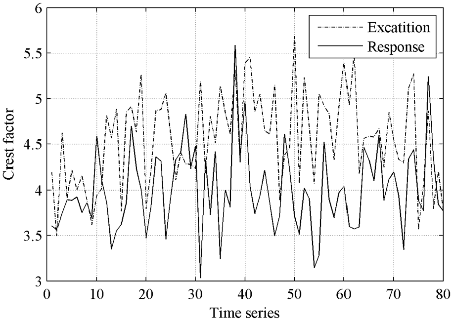
The nonlinear model is simulated at a working height of 19 cm and a damping ratio of 0.4. The time length of the normal road condition signal is 80 s. The input excitation and output response are analyzed with each second as a time series. The crest factor, skewness, and kurtosis of the input excitation and output response are shown in Figures 21 to 23, respectively.
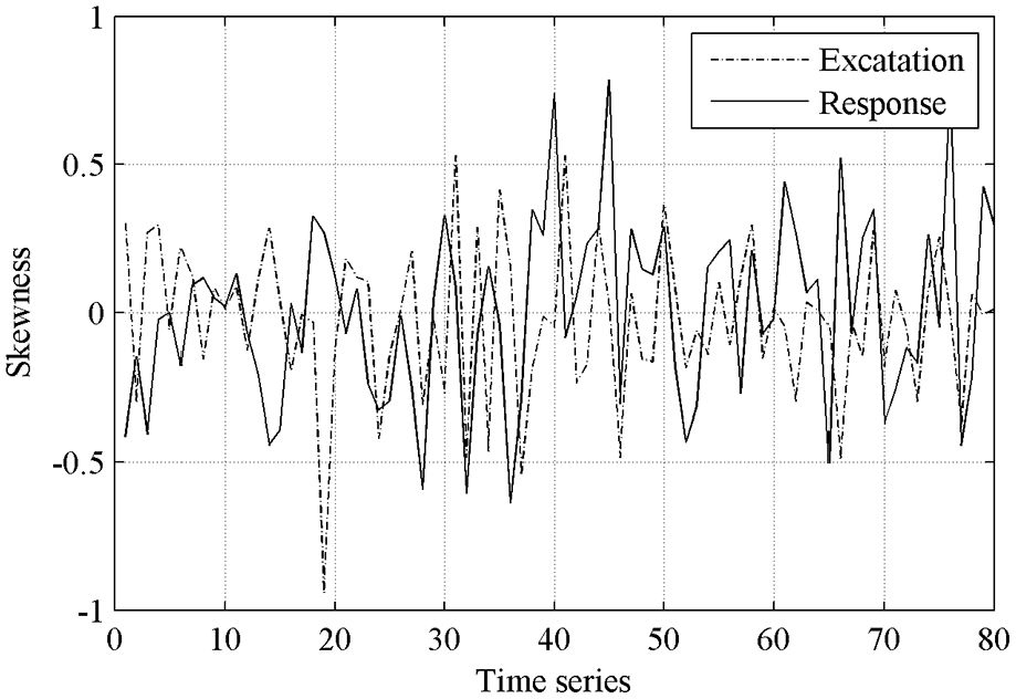
Skewness under normal road condition.
Kurtosis under normal road condition.
It can be seen from Figures 21 and 23 that the crest factor and kurtosis of the response are basically smaller than those of the excitation, and the maximum crest factor and the maximum kurtosis of the response are less than those of the excitation. It indicates that the vibration isolation system has a weakening effect on shock. It can be seen from Figure 22 that both the skewness of the excitation and response are less than 1, indicating that there is no serious asymmetric vibration of the load in the vibration isolation system, and the vibration is relatively stable.
Abnormal road condition
The nonlinear model is simulated at a working height of 16 cm and a damping ratio of 0.6. The time length of the normal road condition signal is 10 s. The input excitation and output response are analyzed with each second as a time series. The crest factor, skewness, and kurtosis of the input excitation and output response are shown in Figures 24 to 26, respectively.
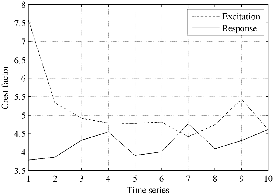
Crest factor under abnormal road condition.
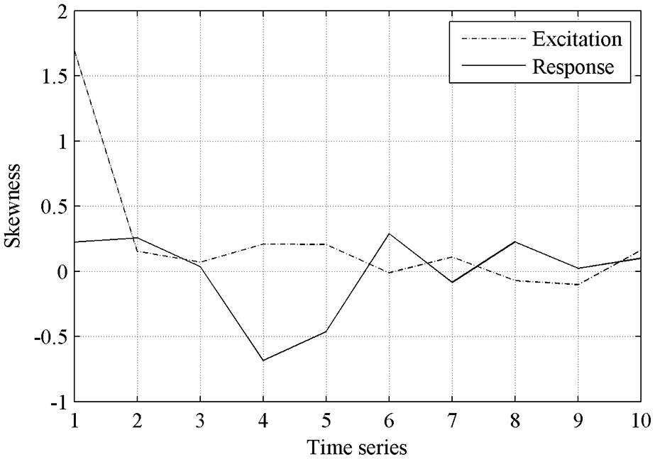
Skewness under abnormal road condition.
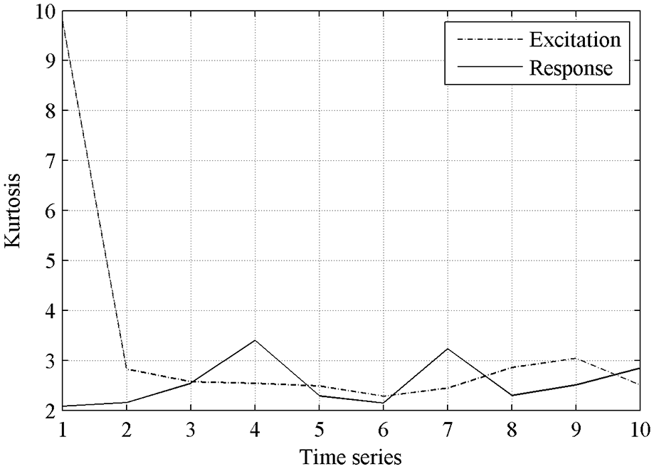
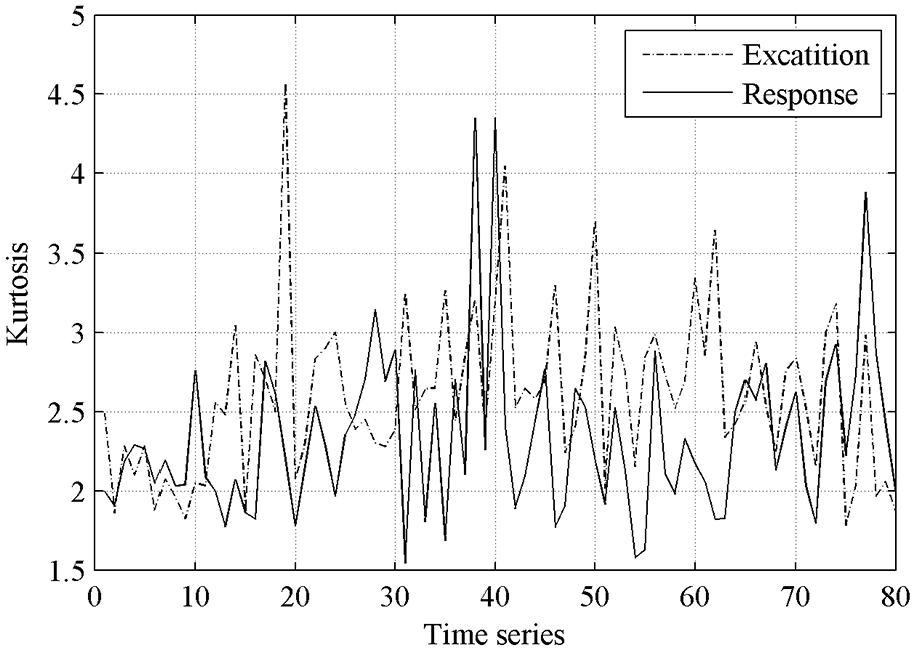
Kurtosis under abnormal road condition.
It can be seen from Figures 24 and 26 that even under abnormal road condition, the crest factor, and kurtosis of the response are less than those of the excitation, too. And the maximum crest factor and the maximum kurtosis of the response are also less than those of the excitation. It indicates that the vibration isolation system has a weakening effect on shock, which is consistent with the law of normal road condition. It can be seen from Figure 25 that both the skewness of the excitation and response are small, indicating that there is no significant large friction and collision in the vibration isolation system, and the system operates smoothly.
In conclusion, the time-domain statistical parameters of the air spring vibration isolation system under two road conditions indicate that the system will reduce the shock of road load, even if the air spring stiffness is nonlinear, and will not cause large asymmetric vibration. Therefore, the vibration isolation system has obvious vibration isolation effect and reliability.
Influence of load eccentricity
During the precision equipment transportation, the ideal situation is that the mass center of precision equipment is located in the symmetrical axis of the vibration isolation system. But generally, this cannot be satisfied, that is, the load eccentricity is a common case. For the common case, if the stiffness of the four air springs remains unchanged, the vibration isolation system will have an initial deflection, which may cause the complex coupled vibration and obvious lateral vibration. In order to avoid this situation, the natural idea is that the height of each air spring is adjusted through changing the internal air pressure of air spring to make the system horizontal (i.e. an equal height control strategy), thereby the initial deflection can be eliminated and a good vibration isolation effect is obtained. However, the initial leveling does not necessarily mean that a good vibration isolation performance can be maintained. Therefore, it is necessary to study whether the air spring equal height control strategy can guarantee the positive effect of the system under different eccentric conditions. Since the excitations of the system in x and y directions are different, the influences of eccentricity in x, y, and diagonal directions on the vibration isolation effect should be analyzed, respectively. Where, the diagonal direction is the direction with an angle of 45° between x and y directions.
Normal road condition
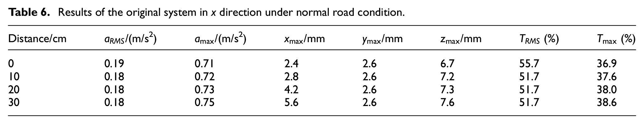
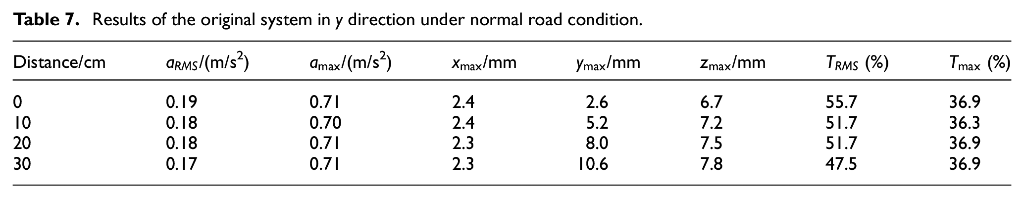
In accordance with the simulation results from the nonlinear model in Section 3, for the air spring working height of 19 cm and the damping ratio of 0.4, the vibration isolation effect under normal road condition is best. Thus, the simulations are performed with this set of parameters. A 50 kg mass block is installed at the center of the support platform of original dynamic model (Figure 5) to simulate the case without eccentricity. And then the mass block is moved by 10, 20, and 30 cm respectively to simulate the case with eccentricity. For these cases, the vibration responses are calculated without changing each air spring stiffness in the original model. The results of x, y, and diagonal direction are shown in Tables 6 to 8, respectively. Where, TRMS is the transmissibility of RMS of acceleration and Tmax is the transmissibility of the maximum acceleration.
Results of the original system in x direction under normal road condition.
Results of the original system in y direction under normal road condition.
Results of the original system in diagonal direction under normal road condition.
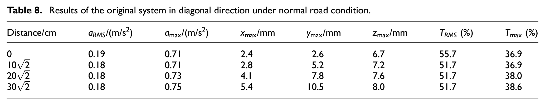
From Tables 6 to 8, it can be seen that with the increase of offset distance, the lateral displacement in a certain direction becomes increasingly larger. To be specific, eccentricity in x direction mainly affects the lateral displacement in x direction, eccentricity in y direction mainly affects the lateral displacement in y direction, and eccentricity in diagonal direction affects the lateral displacements in x and y directions. In addition, the maximum acceleration and the maximum displacement in z direction are slightly increased with the eccentricity. The reason is that the eccentricity in one direction causes the vibration isolation system to deflect in the corresponding direction at the initial stage, and the system remains inclined during vibration isolation process. So the vibration isolation effect deteriorates with the increase of the offset distance. The influence of load eccentricity is necessary to be reduced or eliminated.
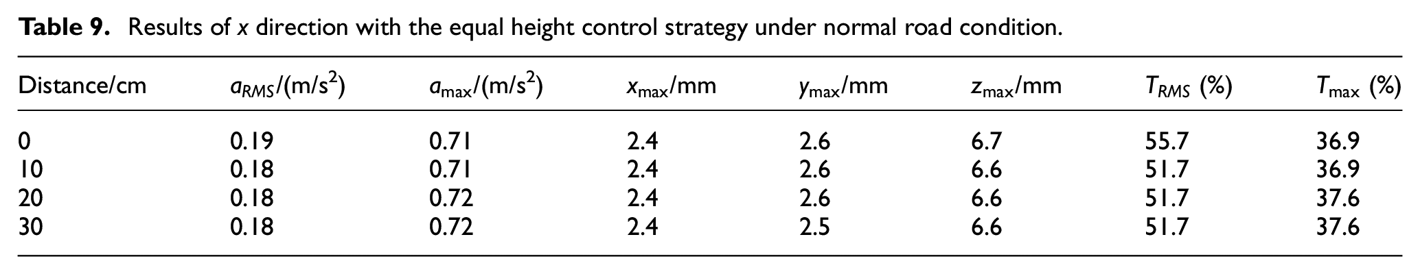
To reduce the influence of load eccentricity and achieve an acceptable vibration isolation effect, we introduce the equal height control strategy in the system. The equal height control strategy means the four air springs working at a same height with the case of eccentricity to ensure PAVS horizontal. To achieve this effect, the stiffness of the air springs at different positions need to be different. The specific process to obtain the stiffness relation of each air spring is shown in Section 2.2. In the case of eccentricity, the loads acting on the air springs at different positions are various. The initial air pressure of air spring can be deduced through the static load and the fixed working height of each air spring at this time, so the stiffness relation of each air spring varying with the height under this initial air pressure can be obtained. This relation is substituted into the dynamic model of Adams for simulation.
To verify the effectiveness of equal height control strategy, the mass block is moved by 10, 20, and 30 cm along x, y, and diagonal directions, respectively. For these cases, the vibration responses at the working height of 19 cm are calculated by introducing the equal height control strategy. The simulation results are shown in Tables 9 to 11, respectively.
Results of x direction with the equal height control strategy under normal road condition.
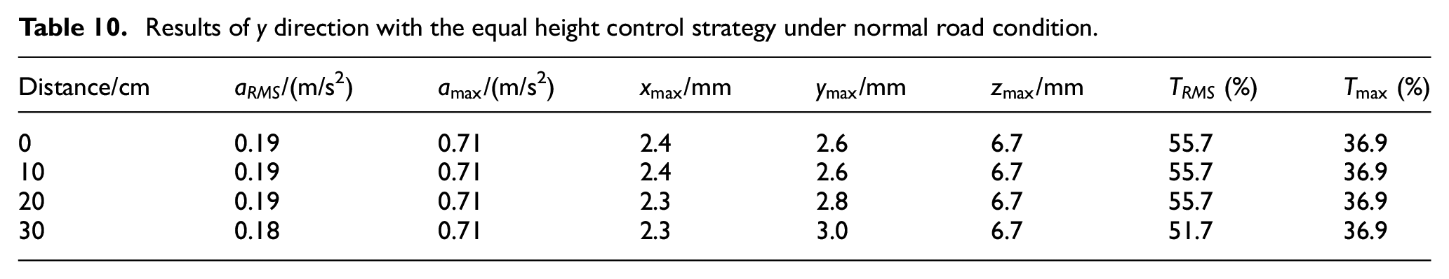
Results of y direction with the equal height control strategy under normal road condition.
Results of diagonal direction with the equal height control strategy under normal road condition.
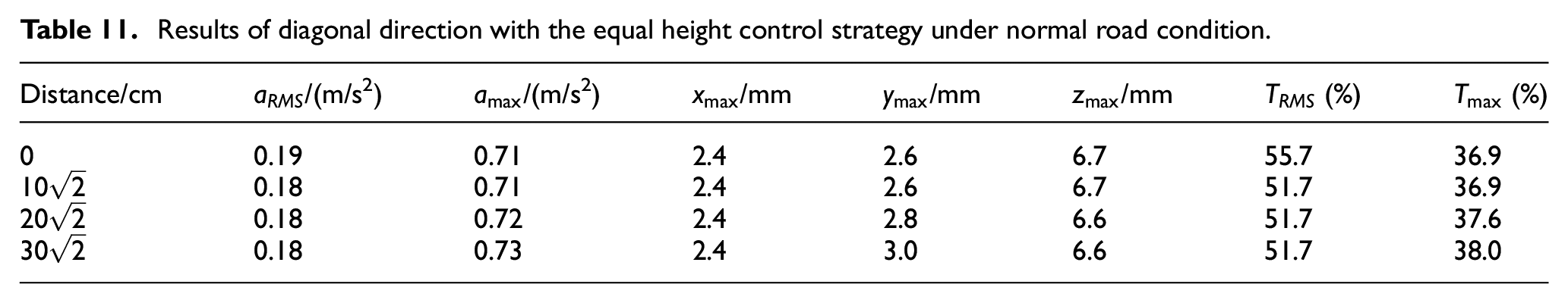
From Tables 9 to 11, it can be seen that, when the equal height control strategy is used, the increase of lateral displacement arising from the eccentricity can be controlled in a small range, and the vibration isolation effect with different offset distances in different directions can be basically the same as the case without eccentricity. So a good vibration isolation effect is achieved.
Abnormal road condition
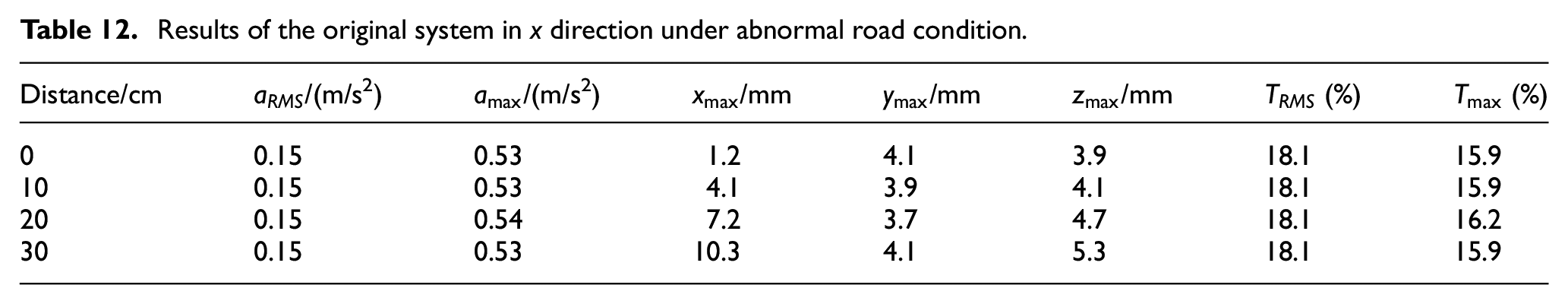
In accordance with the simulation results of the nonlinear model in Section 3, for the air spring working height of 16 cm and the damping ratio of about 0.6, the vibration isolation effect under abnormal road condition is best. Thus, this case is chosen to be studied here. Similarly, a 50 kg mass block is installed at the center of the support platform. Then the mass block is moved by 10, 20, and 30 cm, respectively. For these cases, the vibration responses are calculated without changing each air spring stiffness. The results of x, y, and diagonal direction are shown in Tables 12 to 14, respectively.
Results of the original system in x direction under abnormal road condition.
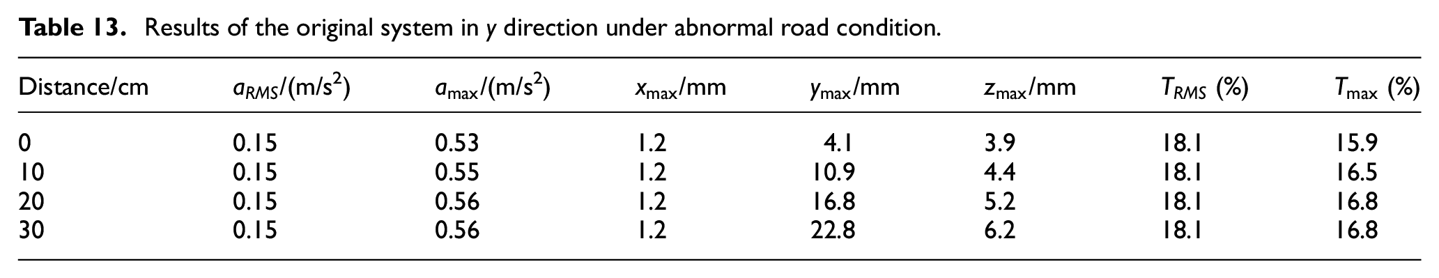
Results of the original system in y direction under abnormal road condition.
Results of the original system in diagonal direction under abnormal road condition.
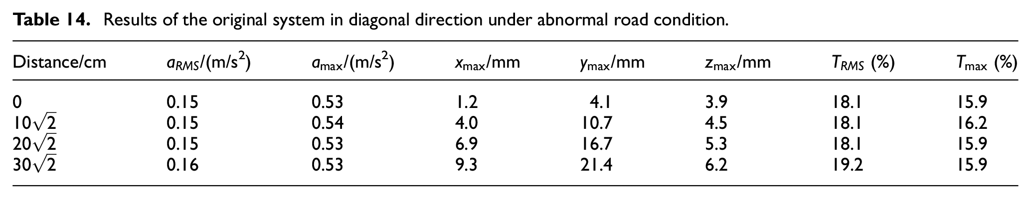
Based on Tables 12 to 14, the similar regulations with Tables 6 to 8 about the influence of the offset distance on the vibration isolation characteristics can be achieved. So the influence of load eccentricity is necessary to be reduced or eliminated.
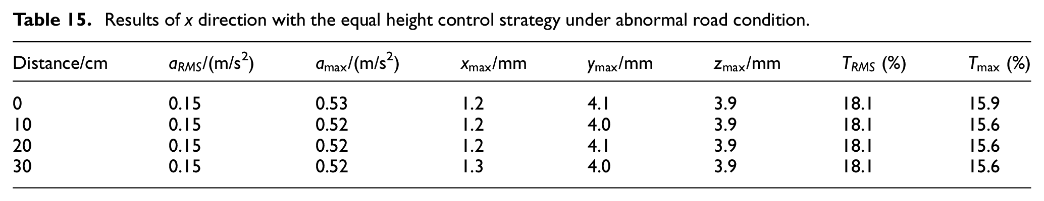
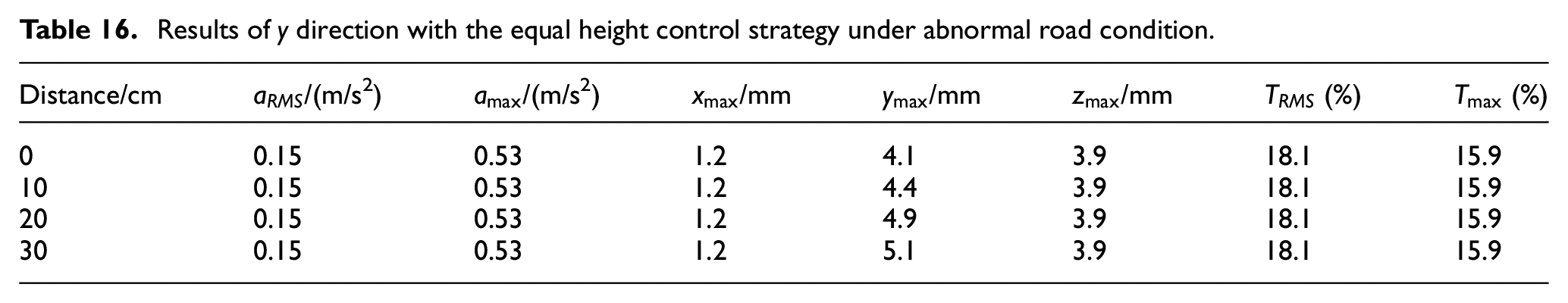
Similarly, the equal height control strategy is introduced in the system. After that, the mass block is moved by 10, 20, and 30 cm along x, y, and diagonal directions, respectively. For these cases, the vibration responses at the working height of 16 cm are calculated, and the results are shown in Tables 15 to 17, respectively.
Results of x direction with the equal height control strategy under abnormal road condition.
Results of y direction with the equal height control strategy under abnormal road condition.
Results of diagonal direction with the equal height control strategy under abnormal road condition.
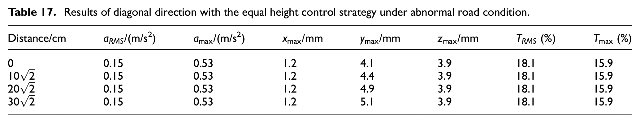
From Tables 15 to 17, it can be seen that, the application of the equal height control strategy can control the lateral displacement arising from the eccentricity effectively, and generate a good vibration isolation effect.
Conclusions
So as to extend the application of PAVS for precision equipment transportation under abnormal road and eccentric load conditions, the nonlinear dynamics simulation model is established based on the measured parameters. The vibration isolation effect of the system is studied for various cases. Meanwhile, aiming at the eccentricity of precision equipment during transportation, the equal height control strategy is introduced and its effect is studied. On the basis of the above investigations, the following conclusions can be made:
Under normal road condition, if there doesn’t exist the eccentricity of the equipment (mass block), the influence of the nonlinearity of air spring stiffness on the vibration isolation characteristics is weak. So the linearity assumption of air spring stiffness is feasible.
Under abnormal road condition, the relative errors between the results from the linear and nonlinear models are up to 18.97%. Therefore, it is necessary to introduce the nonlinearity of air spring stiffness to accurately predict the vibration isolation performance.
Under normal and abnormal road cases, the optimal working height of air spring and the optimal damping ratio are both different. Therefore, the air spring stiffness and the damping are necessary to be adjusted based on the road conditions to obtain a positive vibration isolation effect. Both under normal and abnormal road condition, the vibration isolation system has obvious vibration isolation effect and reliability.
For the case of the eccentricity of precision equipment during transportation, the equal height control strategy is very useful for the vibration isolation system to achieve a satisfactory vibration isolation performance.
The PAVS will reduce the shock of road load, even if the air spring stiffness is nonlinear, and will not cause large asymmetric vibration.
To adapt to the load change, the parameters of PAVS are able to be adjusted during transportation. Therefore, the system is very advantageous to satisfy the various vibration isolation requirements of precision equipment transportation.
Footnotes
Declaration of conflicting interests
The author(s) declared no potential conflicts of interest with respect to the research, authorship, and/or publication of this article.
Funding
The author(s) disclosed receipt of the following financial support for the research, authorship, and/or publication of this article: This work was finically supported by the National Natural Science Foundation of China (Grant No. 51675021 & No. 51675023).