
Abstract
Precision equipment is usually accompanied with vibrations during road or railway transportation. Sometimes the vibration exceeds the given limit, leading to the damage of the equipment. It is necessary to control the vibration during the transportation. However, it is still difficult to adjust the parameters of a designed vibration isolation system for the transportation of different precision equipment under various road conditions. Aiming at satisfying the vibration isolation requirements of different precision equipment, this paper proposes a parallel air spring vibration isolation system based on the principle of limiting lateral deflection. According to the measured parameters, a rigid-body dynamics simulation model of parallel air spring vibration isolation system is established. Then its feasibility is verified, and the optimal parameters of the vibration isolation system are obtained by a simulation. Finally, the vibration isolation system is built and installed in the equipment to carry out the real vehicle transportation test. The test results show that the transportation vibration isolation system based on the parallel air spring structure has not only excellent vibration isolation efficiency but also acceptable lateral stability. The research results in this paper can provide a reference for the design of the vibration isolation system for the large precision equipment transportation.
Introduction
Precision equipment such as satellite and electronic equipment is usually accompanied with vibrations during road or railway transportation. Such vibrations are usually adverse to the mechanical system and even cause the damage of the precision equipment.1–3 Therefore, it is extremely demanded to implement the vibration control to reduce the vibration of the packing box containing the precision equipment during the transportation. However, the vibration during transportation is transiently changed, increasing the difficulty to design the vibration isolation system. The vibration isolator composed of various spring-damping elements, due to its good adaptability and excellent reliability, has become one popular optional method to isolate the vibration of the large packing box.
Nowadays, wire rope springs are widely used as vibration isolation components for vibration isolation platforms of precision equipment. 4 Neill et al. 5 used wire rope isolators for the passive support of the mirrors in the design of the large synoptic survey telescope. Zhou et al. 6 established a model describing the restoring force of wire rope isolators to study vibration isolation effect of electronic equipment. Paolacci and Giannini 7 discussed the wire rope isolator for the seismic protection of high-voltage electrical equipment. According to their experimental work and the mathematical model of the isolator, a 420 kV circuit breaker is equipped with four wire rope isolators. Alessandri et al.8,9 designed a base isolation system that protects high voltage ceramic circuit breakers during seismic events based on an innovative application of wire rope isolators. Zhang et al. 10 designed a damping device based on the wire rope vibration isolators and used it in the airborne optical system. According to the aforementioned research, the main advantage of the wire rope isolator is its ability to provide isolation in all directions. It can be mounted in any orientation to protect structures and equipment excited in any direction. 11 Therefore, it can isolate the vertical vibration and ensure the horizontal safety at the same time, and its intrinsic damping can dissipate the vibration energy greatly. However, the wire rope isolator is installed in the vibration isolation system located between the fixed device and the excitation, thus it is difficult to adjust it in real time to adapt to different vibration isolation requirements or transportation conditions. This leads to the fact that the wire rope vibration isolation system cannot meet the high requirement of the vibration isolation for some precision equipment during the transportation.
To overcome the shortcomings of the wire rope spring, the air spring is a good alternative. In recent years, air springs have been widely used in automotive suspensions, 12 rail vehicles, 13 and other aspects for vibration isolation. Xu et al. 14 developed a new kind of vibration isolation and suppression device with air springs, which can be used for the platform structures in the environments with heavy loading and broadband excitations. Li et al. 15 proposed and developed a hybrid isolator consisting of maglev actuator and air spring for application in active–passive vibration isolation system of ship machinery. The system can effectively isolate broadband vibration and low-frequency sinusoids at the same time. Voigtländer et al. 16 discussed and optimized the vibrational performance of passive pneumatic isolators with air springs for microscopy. Zheng et al. 17 analyzed a wheeled tractor with suspended driver seat including air spring and magnetorheological (MR) damper. Zhang et al. 18 proposed an experience method to isolate the structural vibration by combined electromagnetic actuator and air springs, which can isolate the structural vibration effectively in high-frequency range and constrain the peak response value near the natural frequency. Wang et al. 19 designed an ultra-low frequency 2-degree-of-freedom (DOF) vibration isolator with a positive stiffness (PS) air spring with a negative stiffness (NS) magnetic spring in parallel in order to get wider effective bandwidth and higher performance of vibration isolation in a multiple DOFs system. He et al. 20 provided a novel air spring mounting system (ASMS) for propulsion system consisting of air spring subsystem. The aforementioned research indicates that the air spring is mainly used individually, which may lead to a larger lateral displacement of the vehicle body. 21 Therefore, some devices are required in the lateral direction to ensure the stability.19,21 The system will be complicated, and it may bring unnecessary shock. Due to the limitation of installation space, unnecessary devices may increase the possibility of the motion interference. It cannot guarantee the safety of large precision equipment.
To obtain a better isolation solution and overcome the shortcomings of the wire rope isolator, a vibration isolation system with the parallel air spring system for the transportation of the precision equipment is proposed in this paper. The parallel air spring system can limit the lateral deflection of the air spring. Thus, it is not necessary to add a device to ensure lateral stability. The model simulation and the physical prototype verification indicate that the system can well isolate the vibration and ensure the lateral stability together. The proposed vibration isolation system is advanced in its simple structure, prominent vibration isolation performance, and good lateral stability. This study is expected to provide a reference for the design of the vibration isolation system for the large precision equipment transportation. In future, a changeable stiffness of the vibration isolation system with parallel air springs is to be investigated to provide better vibration isolation characteristics for satisfying different requirements.
The remainder of this paper is organized as follows. A parallel air spring vibration isolation system (PAVS) with the lateral stiffness is proposed in section “PAVS with the lateral stiffness.” The rigid-body dynamics model of PAVS is established and the parameters are designed in section “Dynamics analysis of PAVS.” The experimental verification is carried out in section “Experimental verification.” Finally, the conclusions are drawn in section “Conclusion.”
PAVS with the lateral stiffness
For the packing box containing precision equipment, both the vibration isolation in the vertical direction and the stability in the horizontal direction are required. But generally, the single air spring has a poor capacity of resisting lateral load. If the lateral deflection of the air spring can be restrained, the air spring may have a certain shear stiffness which can be utilized to maintain the lateral safety of the vibration isolation system.
Air spring stiffness test under the limited torsion
The double-bellows type air spring (ContiTech FD110-15) is used in this system. In order to understand the performance of this air spring, a series of static tests on the vertical stiffness and the shear stiffness of the air spring are conducted. The “T” type clamps (for testing the vertical stiffness) and the “Z” type clamps (for testing the shear stiffness) are designed separately. The air spring is clamped on the chuck of the electronic universal testing machine (SANS). Figure 1(a) and (b) shows the experimental setup of the vertical and shear stiffness tests, respectively.
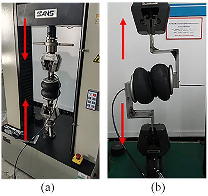
The experimental setup of the air spring stiffness tests: (a) the vertical stiffness test and (b) the shear stiffness test.
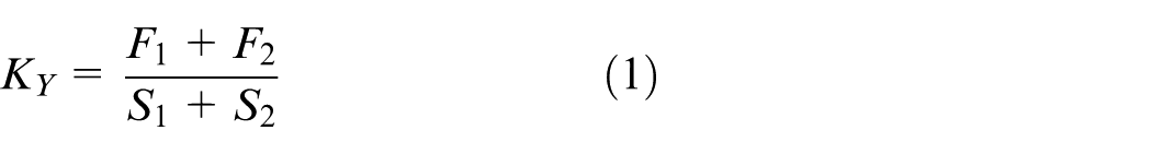
The tested load–displacement curve is plotted in Figure 2. The mass of the internal air in the air spring is constant during one test cycle. The test is performed near the static equilibrium position. The amplitude of the test is 2 cm. The spring stiffness is obtained by calculating the slope of the curve. In general, the vibration amplitude of the air spring during the transportation is smaller than the entire effective working stroke of the air spring (the working stroke of the air spring selected in this paper is 156 mm), thus the stiffness near the working height (corresponding to the static equilibrium position) is approximated to be linear. The static stiffness of the air spring at the working height can be calculated by
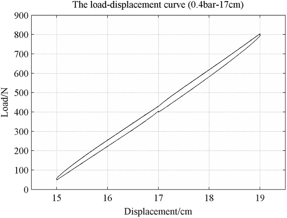
The load–displacement curve.
where
According to the technical specifications of the air spring, the standard working height is 17.5 cm. Therefore, the static equilibrium position range in the test is 15–19 cm, and the internal pressure of the air spring at the static equilibrium position ranges from 0.4 to 1.0 bar. The vertical and shear stiffness of the air spring are listed in Table 1, where the ratio refers to scale of the shear stiffness to the vertical stiffness.
The shear stiffness and the vertical stiffness of air springs.
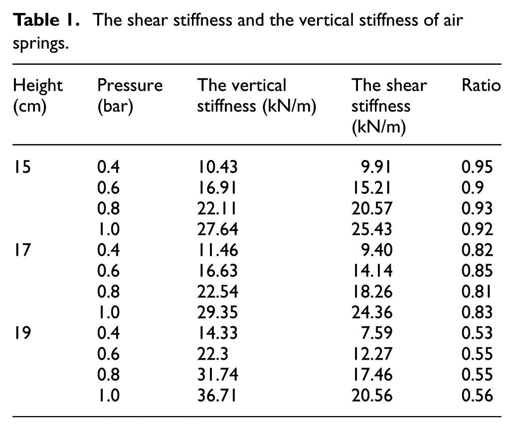
It can be seen from Table 1 that (1) under the same pressure, the relationship between the stiffness (either vertical or shear) and the working height are nonlinear, and the lower the working height of the air spring, the greater the ratio of the shear stiffness to the vertical stiffness; (2) under the same working height, the ratios of the shear stiffness to the vertical stiffness for different internal pressures are very close; and (3) the shear stiffness of an air spring is generally within the range of 55%–95% of the vertical stiffness under the internal pressure of 0.4–1.0 bar and the working height of 15–19 cm.
The air spring characteristics
According to the vertical stiffness test of the air spring, the natural frequency of the air spring vibration isolation system at the specific height and pressure can be calculated by
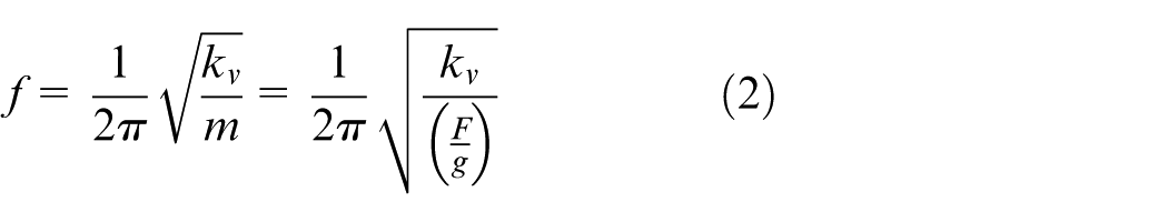
where
The natural frequency of the system at the specific height and pressure.
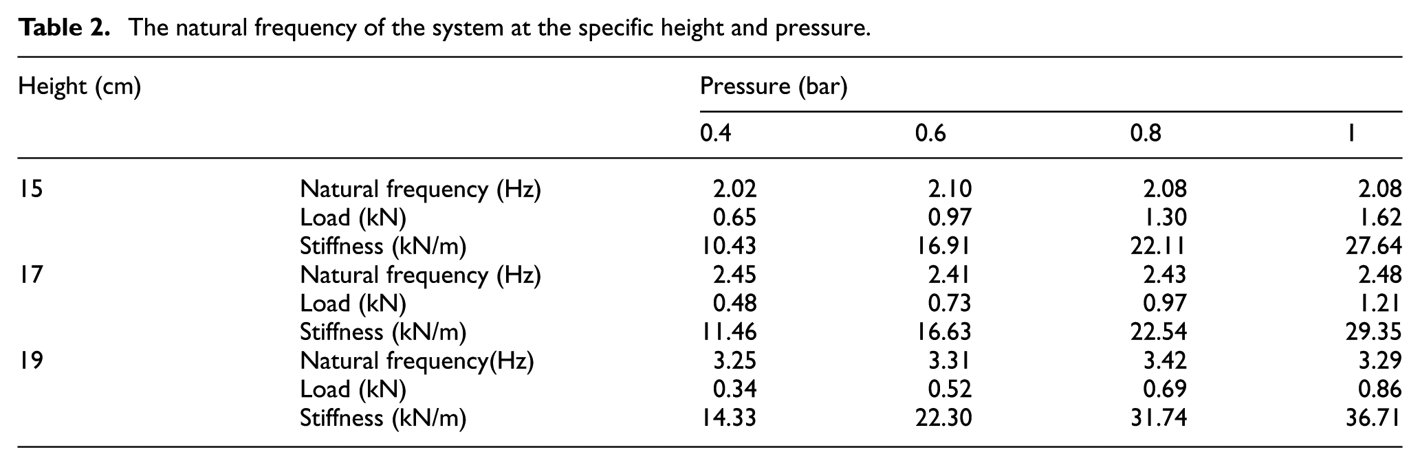
Figure 3 shows that the natural frequencies of the air spring vibration isolation system changed with the air spring pressure at a specific working height. It can be seen that the natural frequency of the air spring vibration isolation system is only related to height, not the pressure. The natural frequency of the system at a certain height is almost unchanged, and the test results are in agreement with the results in the literature. 22
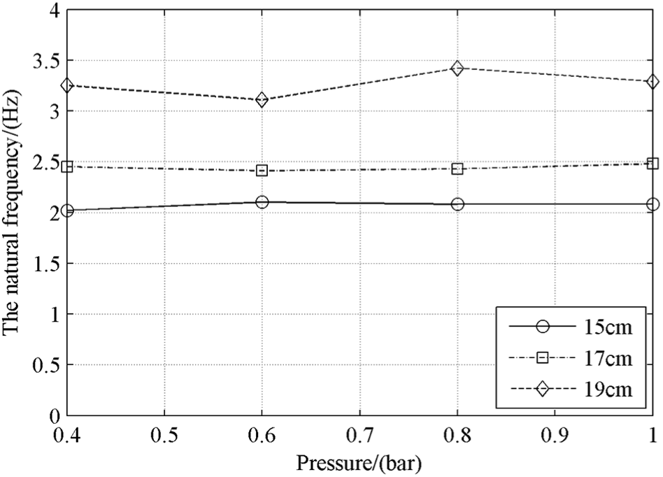
Variation of the natural frequencies with the internal pressure of the air spring.
Layout of PAVS
According to the aforementioned results, the air spring has large shear stiffness under the condition of limiting lateral deflection. Therefore, if the air springs are arranged in parallel, the lateral deflection of the air spring subjected to the lateral load can be restrained. It can ensure the lateral safety of the system and simultaneously meet the requirement of the vertical vibration isolation.
Herein, PAVS is established and its main structure includes a bottom plate, four air springs, two dampers, an adapter plate, and a support platform. The adapter plate and the bottom plate are connected by the air spring, and the dampers serve as the vibration isolation components of the system. The springs are arranged in parallel and distributed at the edge of the bottom plate of the packing box. Because the stiffness of the air spring can be changed by adjusting its internal pressure, the vibration isolation system based on the air spring is adaptive to different loads.
A three-dimensional vibration isolation system is modeled using commercial package SolidWorks, as shown in Figure 4. The precision equipment and the platform are assumed to be homogeneous and rigid. Based on Figure 4, the analysis of the vibration isolation characteristics of PAVS and the optimization of system parameters may be performed to obtain the optimum vibration isolation.
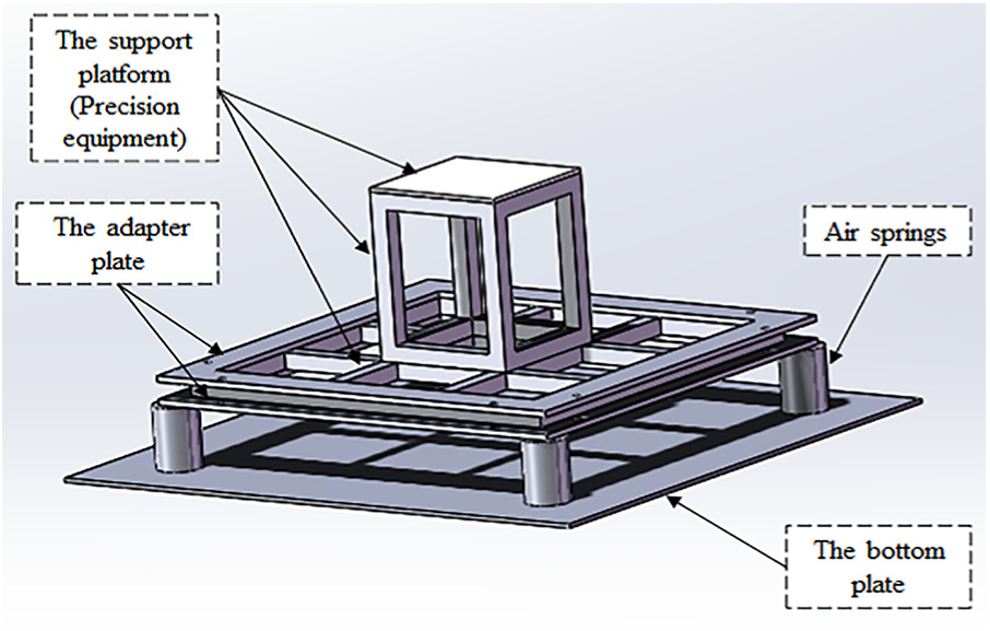
Basic structure of PAVS for packaging and transportation.
Dynamics analysis of PAVS
Dynamics model
The SolidWorks model in Figure 4 is imported into Adams to create a rigid-body dynamics model as shown in Figure 5. The platform is made of aluminum alloy, and the total weight is 145.7 kg. The air spring is represented as a bushing in Adams, which can represent the spring force in three directions. The cross-coupling terms of the bushing element are ignored in the dynamics model. The relevant stiffness parameters of the air spring are obtained from experimental results of section “PAVS with the lateral stiffness.” The damper is represented as a translational spring damper in Adams. The x direction is parallel to the driving direction of the vehicle. The y direction is perpendicular to the driving direction of the vehicle. The z direction is the vertical direction.
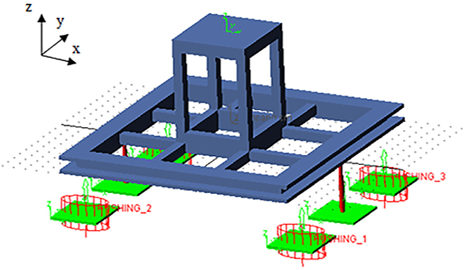
Rigid-body dynamics model of PAVS for packaging and transportation.
The excitation is applied to the bottom plate connected with the air spring and the damper. The vibration acceleration data under typical road conditions at the connections of air springs is collected during the actual transportation. The time length is 80 s and the sampling frequency is 1024 Hz. The acceleration root-mean-square (RMS) value of the input excitation is 0.3486 m/s2, and the maximum vertical acceleration of the input excitation is 1.9281 m/s2. The acceleration signal is converted into displacement signal by the frequency domain integration algorithm. The displacement curves of the connections are shown in Figure 6.
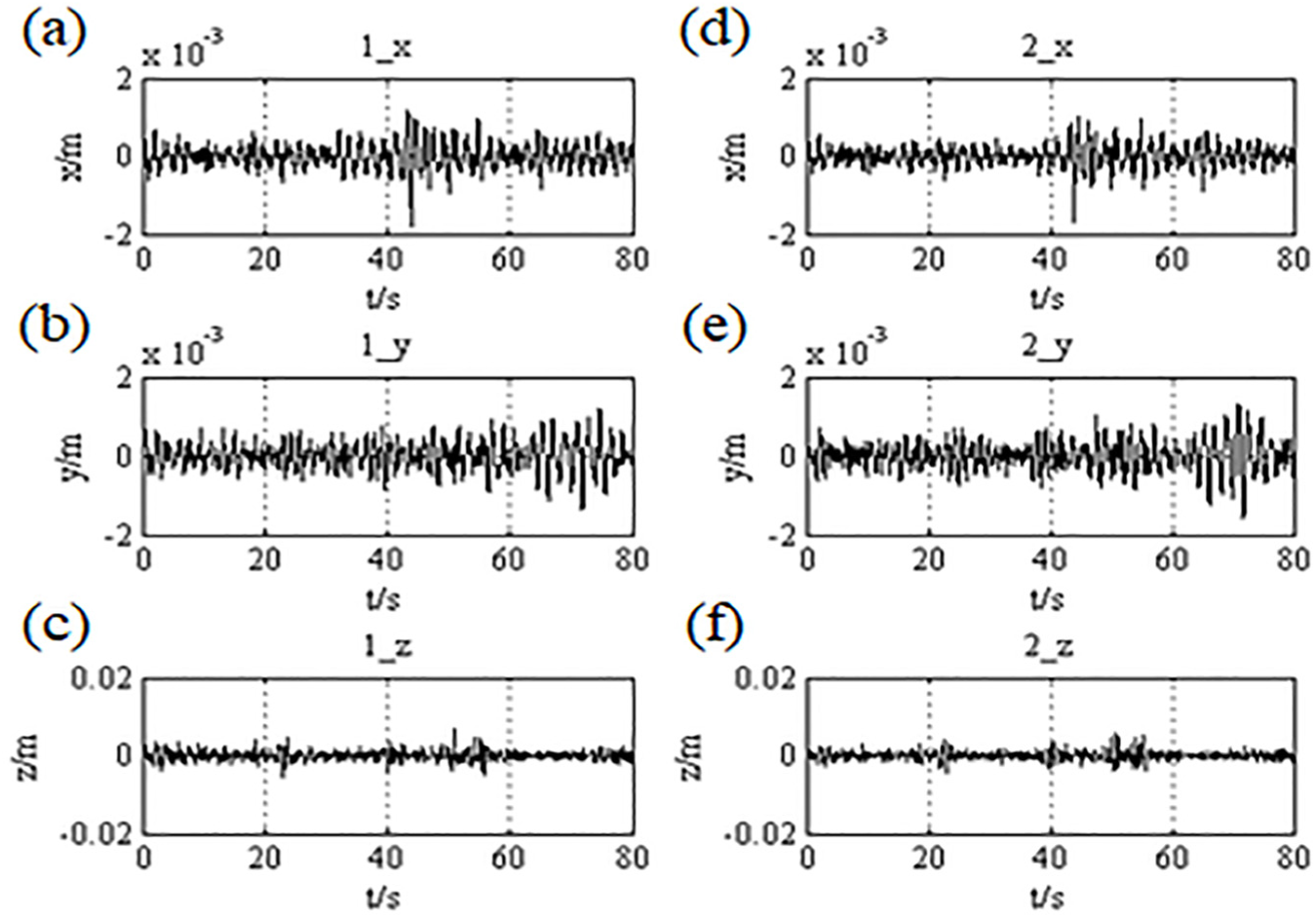
The input displacement curves: (a) the horizontal x-direction displacement at the connection point 1; (b) the horizontal y-direction displacement at the connection point 1; (c) the vertical z-direction displacement at the connection point 1; (d) the horizontal x-direction displacement at the connection point 2; (e) the horizontal y-direction displacement at the connection point 2; and (f) the vertical z-direction displacement at the connection point 2.
The duration time of simulation is set to 80 s. The output location is set at the center point of the support platform as the center point of the precision equipment. During the simulation, the displacement of the air spring is very small relative to the working height of the air spring. Hence, it can be assumed that the air spring stiffness working at a certain working height is not changed.
The precision equipment is of 6 DOF, so the evaluation indexes of the vibration isolation effect are determined by RMS of the vertical acceleration, the maximum vertical acceleration, and the maximum displacement in three directions at the center point. It is worth noting that the amplitude of the precision equipment in the horizontal direction is a very important indicator, considering that the lateral deflection may cause the equipment to collide with the outer casing of the packing box. At the same time, in order to describe the vibration isolation effect of the air spring vibration isolation system, the transmissibility of vibration isolation (the transmissibility of the acceleration RMS value and the transmissibility of the maximum acceleration) is introduced. The transmissibility of the acceleration RMS value is given by
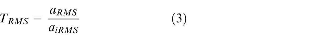
where
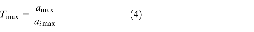
where
Transfer function analysis of the system
The precision equipment is modeled as 6 DOF. The air spring vibration isolation system is a linear multi-degree of freedom system. Before using the real excitation in the simulation, the transfer function of the system can be analyzed to preliminarily predict the vibration isolation effect of the system.
At this time, the working height of the air spring is considered to be 15 cm. The vertical stiffness of the air spring can be calculated by the natural frequency of the air spring system and the load of the air spring using equation (2), and the shear stiffness of the air spring can be calculated according to the ratio of the shear stiffness to the vertical stiffness tested at this working height (0.93 for the case of 15 cm). The damping ratio of the isolation system keeps constant to 0.3; therefore, the corresponding damping coefficient at different working heights can be calculated. When the working height of the air spring is 15 cm, the average of the natural frequency of the system is 2.07 Hz and the static load of each air spring is 357.1876 N. Hence, the vertical stiffness of each air spring is 6161.35 N/m, calculated using equation (2), and the damping coefficient is calculated to be 568.47 N s/m. The system is applied to a z-direction displacement sweep excitation at an excitation amplitude of 10 mm. The transfer function of the vertical vibration of the center point is shown in Figure 7.
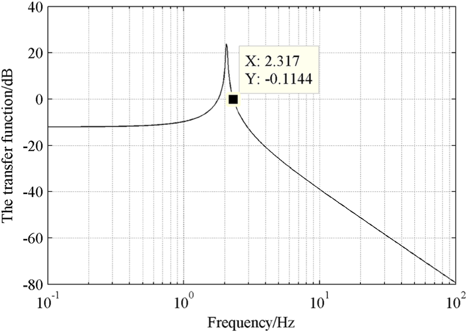
The transfer function of the vertical vibration of the center point.
It can be seen from Figure 7 that the system has a large vibration isolation effect for excitations with a frequency greater than 2.3 Hz. Therefore, it shows that the system has good vibration isolation effect. The following simulations will be performed using real excitations to ensure that the system also has better vibration isolation performance.
Influence of key parameters on vibration isolation performance of the system
It is well known that the vibration isolation effect of a system containing an air spring is significantly affected by its vertical, shear stiffness, and its damping magnitude. To obtain the best vibration isolation performance, the influence of different factors on the isolation effect is investigated, and then the parametric optimization is performed.
Resulting from the experimental results of the air spring, it is found that the air spring stiffness is sensitive to the working height of the air spring, and the ratio of the shear stiffness and the vertical stiffness of the air spring is also dependent on the working height. Therefore, for the vibration isolation system in this paper, the factors affecting the vibration isolation effect can be simplified as the working height of the air spring and the magnitude of the damping.
Influence of the air spring working height
According to the intrinsic characteristics of the air spring vibration isolation system, the natural frequency of the system is only related to the height of the air spring. Moreover, the natural frequency of the system affects the vibration isolation effect. Therefore, it is necessary to study the influence of the working height of the air spring on the vibration isolation effect. Under the condition that the optimal working height of the air spring (15–19 cm) of this system and the installation height requirement of the vibration isolation system for the precision equipment (the maximum working height of air spring is 20 cm), the vibration responses with the air springs working at the height of 15, 17, and 19 cm are calculated, respectively. At each working height, the vertical stiffness of the air spring can be calculated by the natural frequency of the air spring system and the load of the air spring using equation (2), and the shear stiffness of the air spring can be calculated according to the ratio of the shear stiffness to the vertical stiffness tested at different working heights (0.93 for the case of 15 cm; 0.83 for the case of 17 cm; and 0.55 for the case of 19 cm). The damping ratio of the isolation system keeps constant to 0.3; therefore, the corresponding damping coefficient at different working heights can be calculated. Then the model is simulated by using these parameters. All the evaluation indexes of the vibration isolation effect are shown in Table 3.
The influence of the working height (the damping ratio is 0.3).
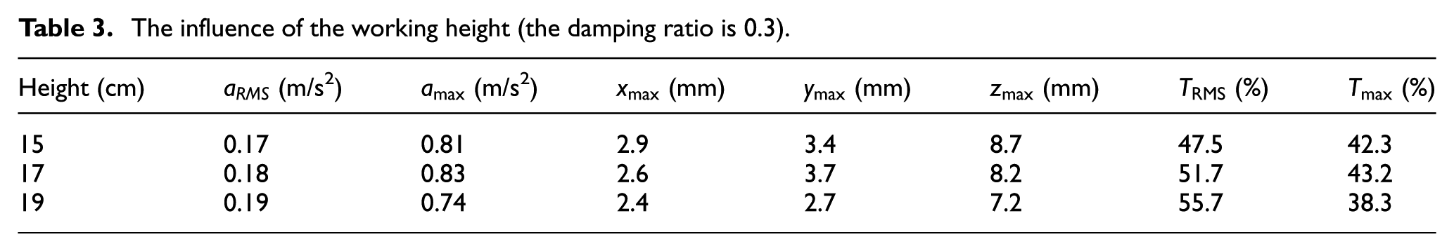
It can be seen from Table 3 that RMS of the vertical acceleration at the center point of the model increases with the increase of the working height of the air spring, while the maximum vertical acceleration at the center point decreases with the increase of the working height of the air spring. The maximum vertical displacement at the center point decreases with the increase of the working height of the air spring, and the maximum displacement at the center point in both horizontal directions also decrease with the increase of the working height of the air spring.
According to the actual experience, it is likely that the maximum acceleration is more probable to cause damage of the precision equipment than RMS of the acceleration. Therefore, it is preferred to adjust the parameters reducing the maximum acceleration in the design of the vibration isolation system. In addition, it is necessary to control the maximum displacement in all three directions as small as possible. Therefore, when the working height of the air spring is 19 cm, the vibration isolation effect of the system is the best.
Influence of the damping ratio
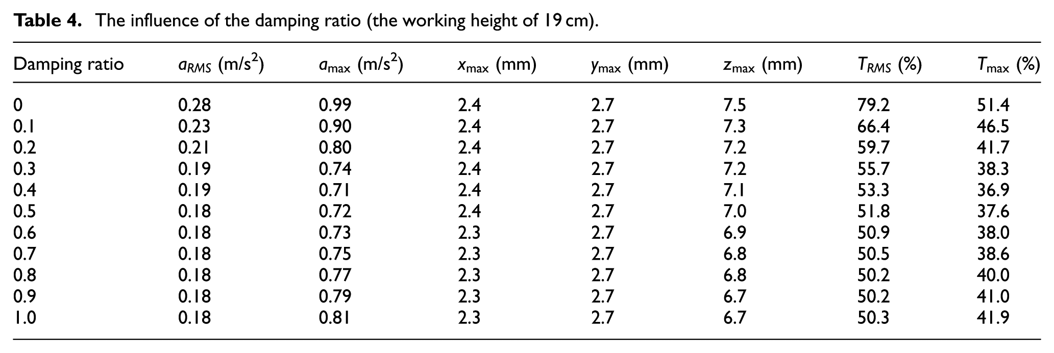
For the vibration isolation system, it is essential to match the stiffness with the damping to obtain the optimum isolation effect. According to the simulation results in the previous section, the vibration isolation effect of the system is the best at the working height of 19 cm. Hence, the model is simulated for different damping ratios at the working height of 19 cm. All the evaluation indexes of the vibration isolation effect are shown in Table 4. The variations of RMS of the vertical acceleration and the maximum vertical acceleration at the center point with the damping ratio are plotted and shown in Figures 8 and 9, respectively.
The influence of the damping ratio (the working height of 19 cm).
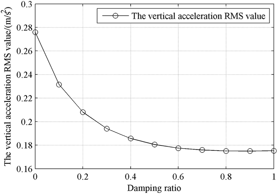
Variation of RMS of the vertical acceleration at the center point with different damping ratios.
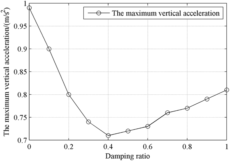
Variation of the maximum vertical acceleration at the center point with different damping ratios.
From Table 4 and Figures 8 and 9, the conclusions reached are as follows:
The vibration isolation effect of the vibration isolation system with damping is much better than that of the system without damping, and all the indexes are significantly reduced. RMS of the vertical acceleration at the center point decreases with the increase of the damping ratio. In the case of the critical damping (the damping ratio is 1.0), RMS of the vertical acceleration at the center point begins to increase which is larger than that when the damping ratio is 0.9.
For the maximum vertical acceleration at the center point, the optimum damping ratio is 0.4. When the excitation frequency is less than 1.414 times of the natural frequency of the system, the larger the damping ratio, the smaller the transmissibility of the acceleration. When the excitation frequency is more than 1.414 times of the natural frequency of the system, the larger the damping ratio, the larger the transmissibility of the acceleration. The input excitations contain various frequency components and have large amplitude at different frequencies. The influence of the damping ratio on the transmissibility is very complicated. The simulation results show that the maximum vertical acceleration at the center point is minimum when the damping ratio is 0.4.
Because the damper is installed in the vertical direction, the change of the damping ratio has little influence on the maximum displacement of the vibration isolation system in both horizontal directions. The maximum displacement in the vertical direction decreases with the increase of the damping ratio. The larger the damping ratio, the smaller the influence on the maximum displacement in the vertical direction.
According to the actual experience, it is likely that the maximum acceleration is more probable to cause the damage of the precision equipment than RMS of the acceleration. Therefore, the vibration isolation effect of the system is the most optimizational when the damping ratio is 0.4. Based on the aforementioned simulation results, it can be concluded that the optimized vibration isolation parameters of the air spring are its working height of 19 cm and the damping ratio of 0.4.
Experimental verification
Layout of the experimental platform
To verify the feasibility of PAVS, based on the simulation model and parameters in sections “PAVS with the lateral stiffness” and “Dynamics analysis of PAVS,” a prototype platform is designed and built. The platform is mainly composed of three parts: the vibration isolators including four air springs and two dampers, the gantry, and the bottom plate. The size of the bottom plate is
Figure 10(a) and (b) shows the prototype platform structure and the sensors’ locations, respectively. Figure 10(c) shows the schematic diagram of the experimental setup. Sensors 1–4 measure the vertical acceleration signal excited by the system, and sensors 5 and 6 measure the vertical acceleration response of the system at the corresponding positions. Sensor 7 is a three-axes acceleration sensor which can measure the acceleration responses in three directions.
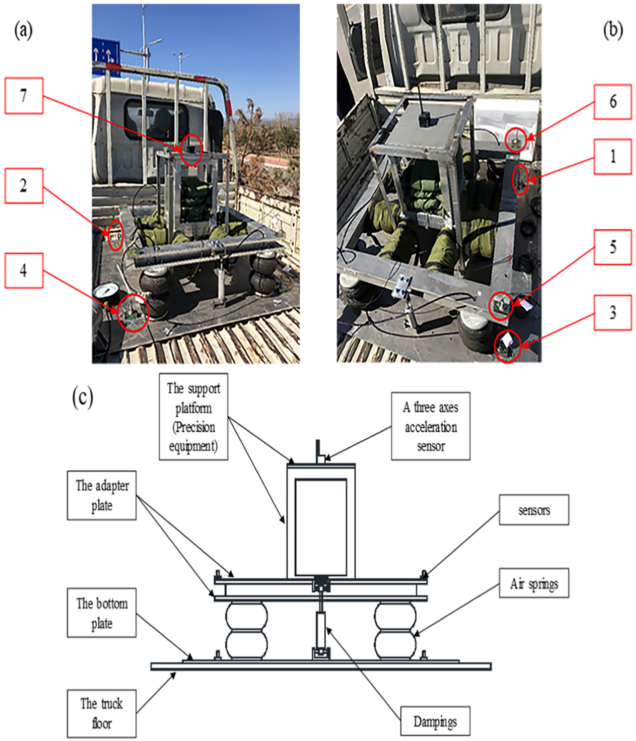
The vibration isolation test: (a–b) the prototype platform structure and the sensors’ locations and (c) the schematic diagram of experimental setup.
Vibration isolation test during the transportation
The prototype platform is installed on the truck. The truck experiences the conditions of starting, stabilizing, turning, braking, and so on during the road test. The whole sampling time is 220 s. Here, the total vibration isolation performance of the system is investigated. In addition, since the transportation is mostly operated at a stable condition with a speed of about 50 km/h, the vibration isolation performance of the system under stable conditions is emphatically analyzed.
The test signals of the vertical acceleration at the excitation positions (points 1–4) are shown in Figure 11. The test signals of the vertical acceleration at the response points 5 and 6 (up the air spring) are shown in Figure 12. The test signals of sensor 7 at the center point of the support platform are shown in Figure 13. The statistics parameters of each test signal in the whole sampling time are shown in Table 5.
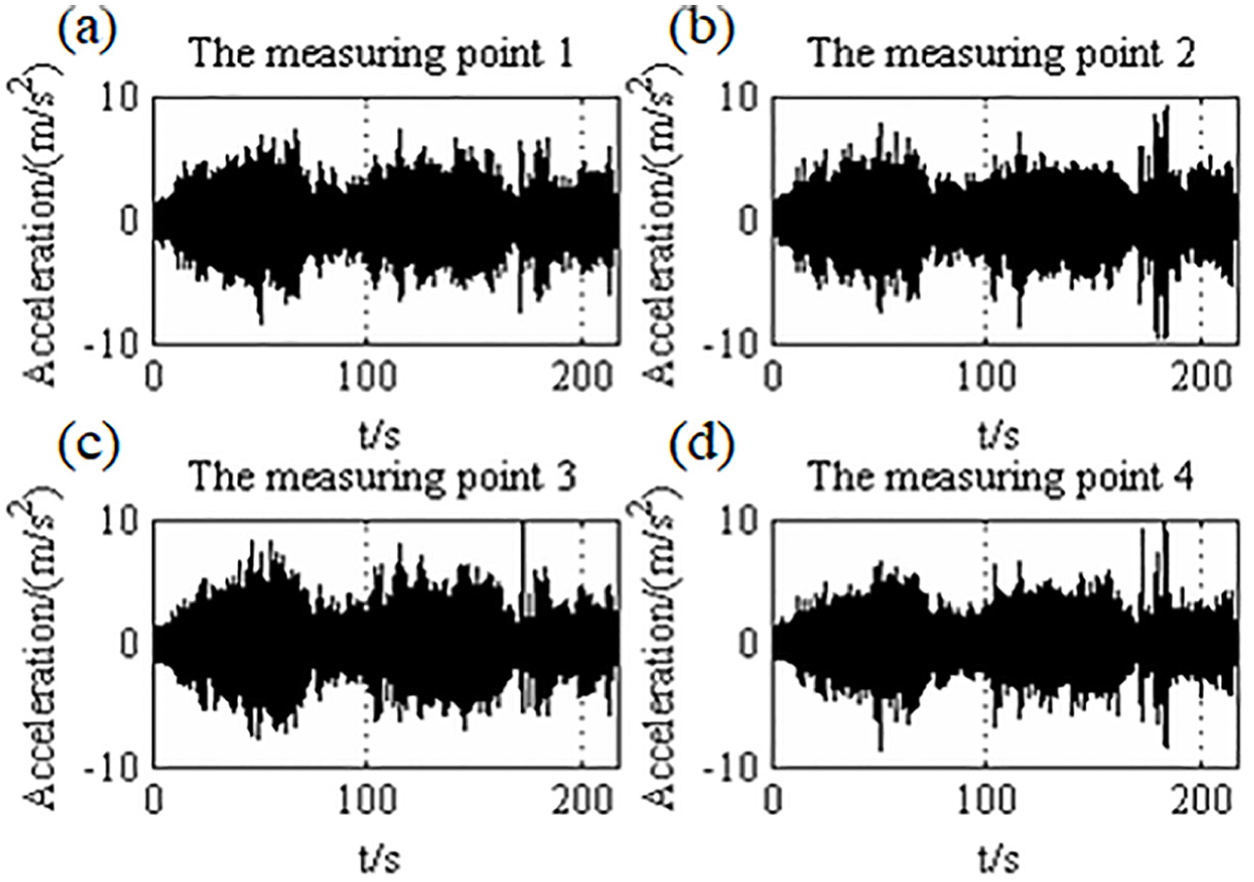
The system excitation: (a) the vertical acceleration test signal at the measuring point 1; (b) the vertical acceleration test signal at the measuring point 2; (c) the vertical acceleration test signal at the measuring point 3; and (d) the vertical acceleration test signal at the measuring point 4.
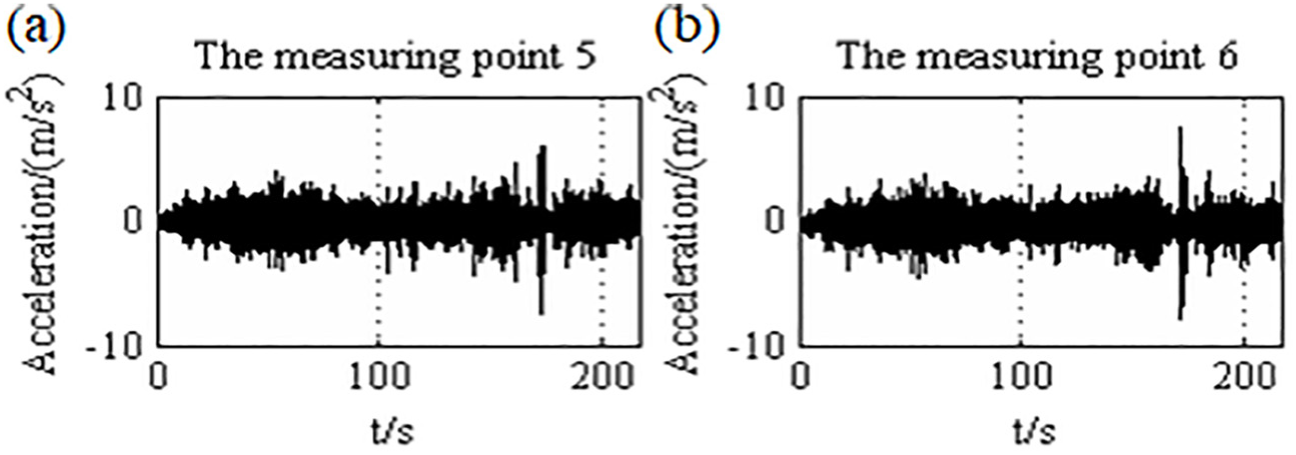
The response of the system up the air spring: (a) the vertical acceleration test signal at the measuring point 5 and (b) the vertical acceleration test signal at the measuring point 6.
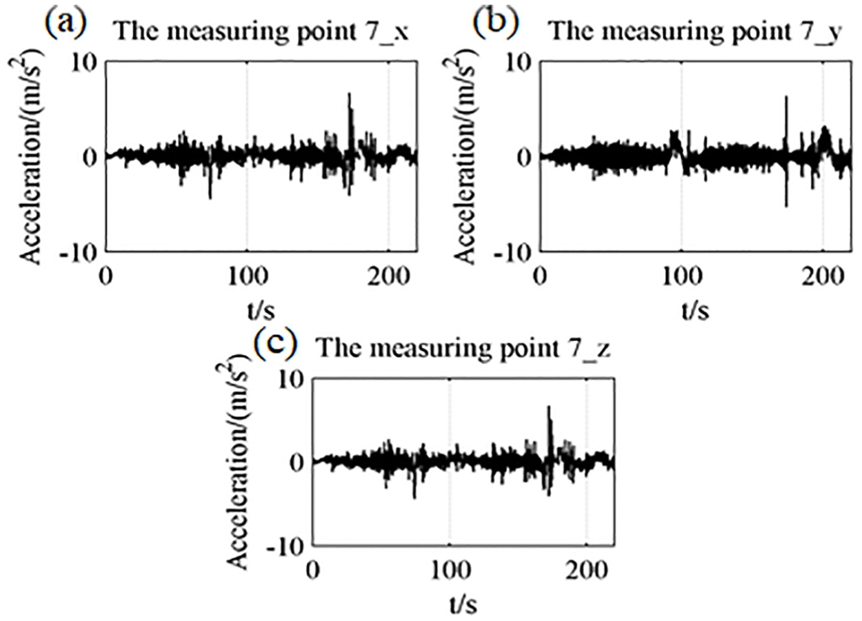
The response of the system at the center point of the support platform: (a) the horizontal x-direction acceleration test signal at the measuring point 7; (b) the horizontal y-direction acceleration test signal at the measuring point 7; and (c) the vertical acceleration test signal at the measuring point 7.
The statistics of each test signal in the whole sampling time.
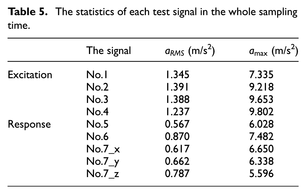
From Figures 11–13, it can be seen that the vibration isolation system has a strong ability to isolate vibration. Table 5 indicates that before the isolation, RMS of the acceleration ranges from 1.391 to 1.237 m/s2, and the accelerations ranges from 9.802 to 7.335 m/s2. The signal 7_z is the vertical acceleration response at the center point. The transmissibility of the acceleration RMS value at the center point is in the range of 56.6%–63.6%, and the average value is 58.9%. The transmissibility of the maximum acceleration at the center point is in the range of 57.9%–76.3%, and the average value is 63.2%. The transmissibility of the maximum acceleration is a little bit large because the connections of dampers are rigid in the test, and the vibration isolation system has a bad vibration isolation effect on the shock. Even in this case, the vibration isolation system can still work well.
The duration of 40–60 s is a stable driving condition with a speed of about 50 km/h on the road. The statistics parameters of each test signal in this duration are shown in Table 6.
The statistics of each test signal.
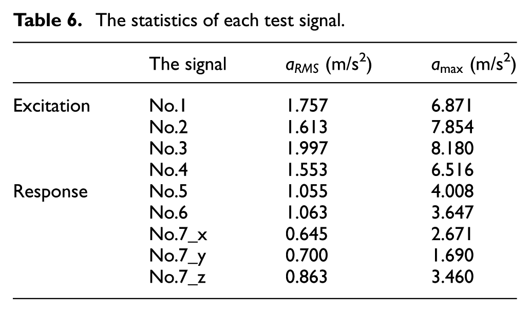
Table 6 indicates that before the isolation, RMS of the acceleration ranges from 1.997 to 1.553 m/s2, and the accelerations ranges from 8.180 to 6.516 m/s2. The signal 7_z is the vertical acceleration response at the center point. The transmissibility of the acceleration RMS value at the center point is in the range of 43.2%–55.6%, and the average value is 50.4%. The transmissibility of the maximum acceleration at the center point is in the range of 42.3%–53.1%, and the average value is 47.5%. The comparison between the simulation and test results is shown in Table 7.
The comparison between the simulation and test results.
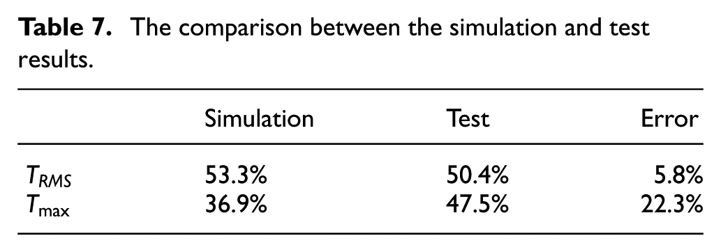
It can be seen from Table 7 that the error of the acceleration RMS value between the simulation and experiment is small, but the error of the transmissibility of the maximum acceleration is a little bit large. The reason is that the corresponding excitation during the test is different from that in the simulation, and the prototype platform is made of hollow aluminum frame. In practice, it cannot be regarded as an ideal rigid body. The structure itself has a vibration isolation influence on the system. Therefore, there are differences between the results of the test and the simulation. However, both the test and simulation results show that the system has good vibration isolation performance.
By testing the vibration isolation system of the prototype platform and analyzing the test results, the following conclusions are obtained: the established vibration isolation system has a strong ability to weaken the vibration. The transmissibilities of the acceleration RMS value and the maximum acceleration at the center point are greatly reduced to 50.4% and 47.5%, respectively. The system has good vibration isolation performance, which is consistent with the simulation prediction. In further research, the system can be optimized to ensure the optimal configuration of the air spring and the damper to obtain better vibration isolation characteristics.
Conclusion
To satisfy the practical requirement of the vibration isolation for the large precision equipment during transportation, a PAVS is designed based on the trick of limiting lateral deflection in this paper. The corresponding dynamics analysis is carried out to obtain the optimum vibration isolation parameters. Based on the investigation, the following conclusions are drawn:
For the established PAVS, under the condition that the working height of the air spring of 19 cm and the damping ratio of 0.4, the excellent vibration isolation effect can be reached. The transmissibilities of the acceleration RMS value and the maximum vertical acceleration at the center point are reduced to 53.3% and 36.9%, respectively. The maximum lateral displacement can be controlled below 10 mm. The effectiveness of PAVS is verified by experiments.
PAVS shows high vibration isolation efficiency and good lateral stability. It is promising in vibration isolation for the large precision equipment during transportation.
The vibration isolation parameters of PAVS can be adjusted to match the change of loads during transportation. Therefore, the system can fully meet the vibration isolation requirements of the transportation of the complex equipment.
Footnotes
Declaration of conflicting interests
The author(s) declared no potential conflicts of interest with respect to the research, authorship, and/or publication of this article.
Funding
This work was finically supported by the National Natural Science Foundation of China (grant nos.: 51675021 and 5167 5023).