
Abstract
In the control research on the rotary crane systems with double-pendulum effect, a motion trajectory with both simple structure and excellent robust performance is proposed to achieve the positioning of the boom and the suppression of the load sway. The presented trajectory consists of an anti-swing component and a boom positioning component, where the first part is used to achieve the sway angle elimination without affecting boom positioning; the second one is used to move the boom to the desired location precisely. The Lyapunov technique, LaSalle’s invariance theorem, and Barbalat’s lemma are used to prove the excellent performance of the method. Eventually, the effectiveness of the proposed method was verified through a large amount of simulation data analysis.
Keywords
Introduction
There are many types of cranes, which can be divided as overhead cranes, rotary cranes and tower cranes according to their differences in structure. Due to the simple structure and small space occupation, rotary cranes have been used in various workplaces, such as construction sites and ports in recent years. However, during the lifting process, with the change of the boom speed, the load will form a different sway state. At the same time, when the shape of the load is irregular or the mass of the hook cannot be neglected, the crane system will exhibit a more complex load sway phenomenon. This load sway will not only reduce the working efficiency of the crane but also bring potential safety hazards and even cause accidents. Because the closed-loop methods can provide strong robustness performance, a large number of related control methods, including adaptive control,1–4 sliding mode control,5–7 Lyapunov-based nonlinear method,8–15 fuzzy control,16–18 and so on, have been proposed. However, these methods need to feedback the load sway information; therefore, the control performance entirely depends on the accuracy of the information.
On the other hand, researchers have presented open-loop control methods to solve the above problems. Fujioka and Singhose 19 applied the method based on input shaping to the anti-sway control of the double-pendulum overhead crane successfully, and achieved good control effect. They also proposed zero vibration derivative (ZVD) shaper, zero vibration derivative-derivative-derivative (ZVDDD) shaper, and specified-insensitivity (SI) shaper for cranes.20–22 In recent years, Ramli et al. 23 proposed an input shaping control method based on neural network for the problem of the change of the load quality during the lifting process, and successfully applied it to the overhead crane. Meanwhile, to solve external disturbance, such as wind disturbance, Abdullahi et al. 24 combined an adaptive controller and a command shaper for sway controls of a three-dimensional (3D) overhead crane. For the vibration control problem of the system, Jaafar et al. 25 proposed a model reference command-shaping method, which was successfully applied to the double- pendulum overhead crane. In addition, with the in-depth study of this method by many scholars, many similar control methods based on input shaping have been proposed.26–32 Besides, optimal methods, which can solve the optimization problem in motion planning effectively, were presented in previous studies.33–35
However, these control methods may not be applied to the case where the system parameters are unknown. Further, the above methods need to recalculate the corresponding parameters, when the load transport distance changed. Regarding the aforementioned issue, Zhang et al. 36 proposed a control method based on online trajectory planning for a double-pendulum overhead crane system. This method can simultaneously achieve precise positioning of the trolley and quickly suppress load sway. Compared with double-pendulum overhead cranes, double-pendulum rotary cranes are more widely used in practice because of their small footprint and high transportation efficiency. However, unlike the double-pendulum overhead cranes, the hook and load sway analysis in the rotary crane system are more complicated, the sway angle coupling is stronger, and the control process is more challenging.
To this end, the nonlinear dynamic model of a double-pendulum rotary crane is derived first. Then, after careful analysis of the foregoing model, an online motion planning method is proposed. It can be calculated online without accurate model of crane system and being designed in advance. The Lyapunov technique, LaSalle’s invariance theorem, and Barbalat’s lemma are used to prove the excellent performance of the method. Eventually, the effectiveness of the proposed method is demonstrated by simulation results.
Problem statement and model transformation
Problem statement
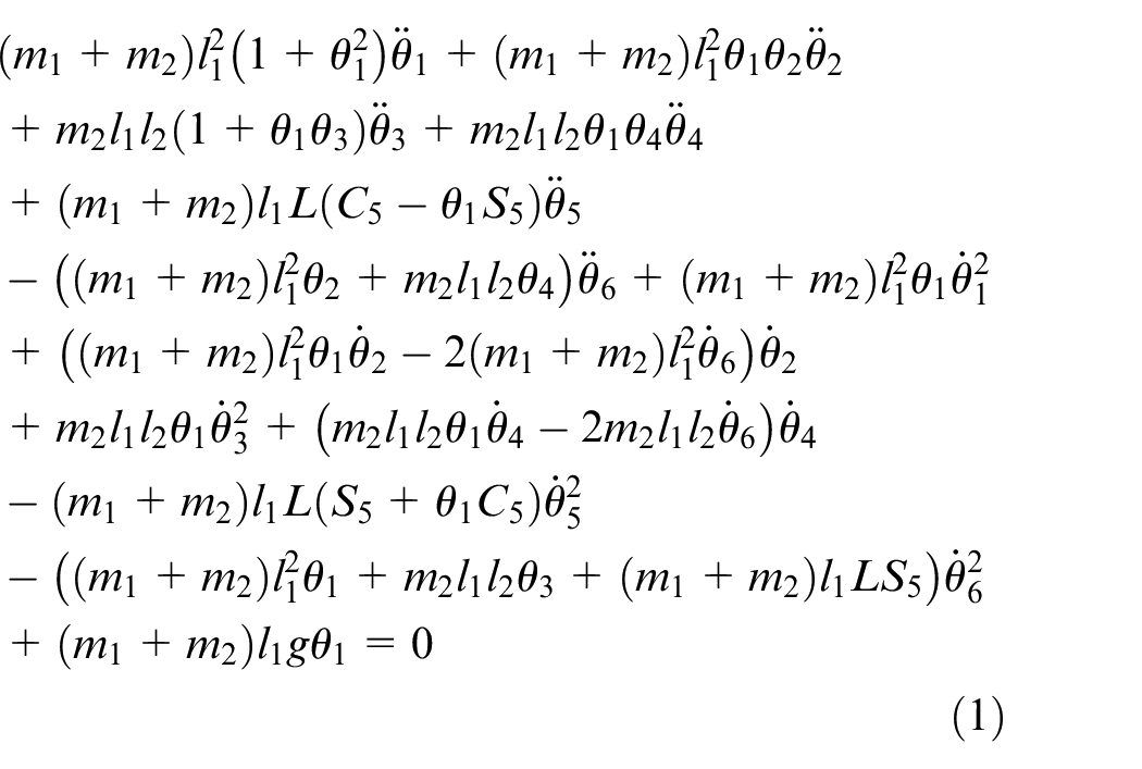
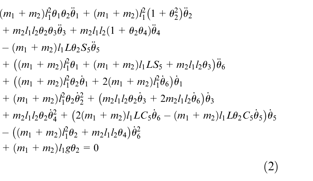
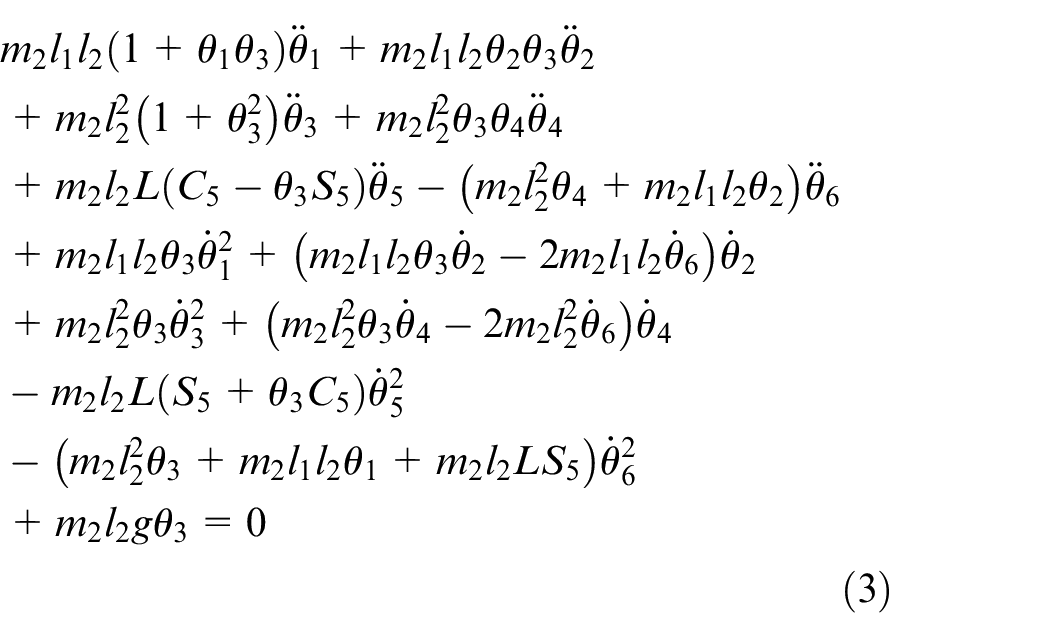
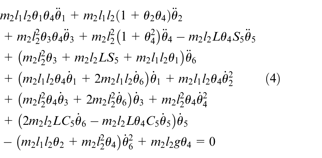
In this section, the dynamic analysis of the rotary crane with double-pendulum effect is carried out in the light of the structure diagram shown in Figure 1 first and, then, combined with the expression of Lagrange’s kinematics equations. Finally, the following dynamic model of this type of crane system will be obtained 2
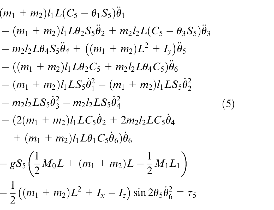
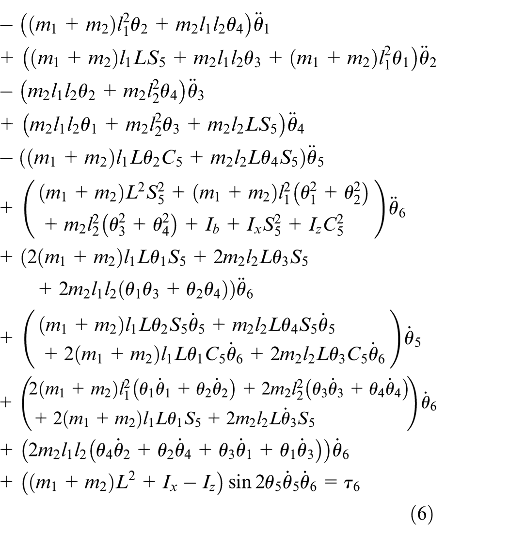
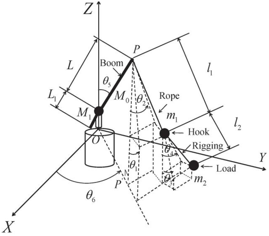
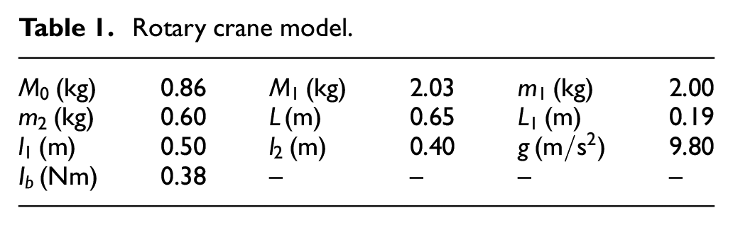
Rotary crane model.
The detailed definition of the parameters in equations (1)–(6) can be found in Ouyang et al. 2
Model transformation
It is assumed that
Hence, the following results can be obtained from equations (1)–(4)
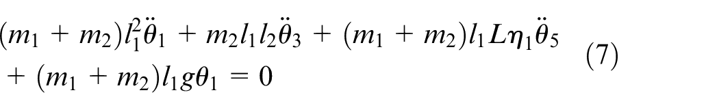
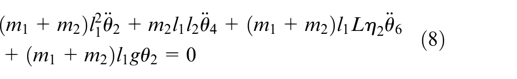


where
Through a series of mathematical operations, we have
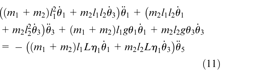
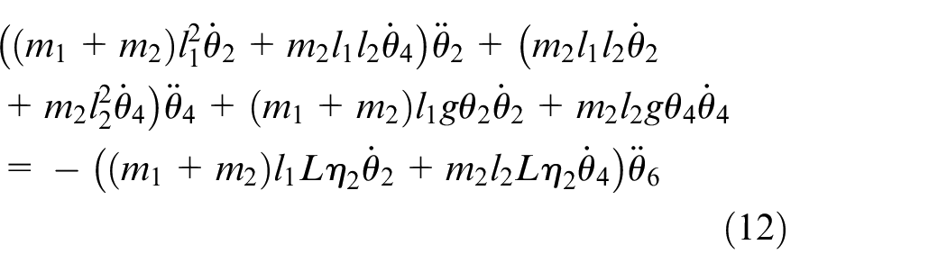
Equations (11) and (12) describe the coupling relationship between the vertical boom angle and the load sway angles in vertical direction and between the horizontal boom angle and the load sway angles in the horizontal direction, respectively.
Based on the above relationship, an online motion trajectory method that can simultaneously achieve the control objectives of boom positioning and load sway suppression will be designed in this paper.
Trajectory construction
Sway rejection component design
First, the sway rejection component for the crane system can be designed as follows


where
Theorem 1
The double-pendulum load sways
Proof
The following function
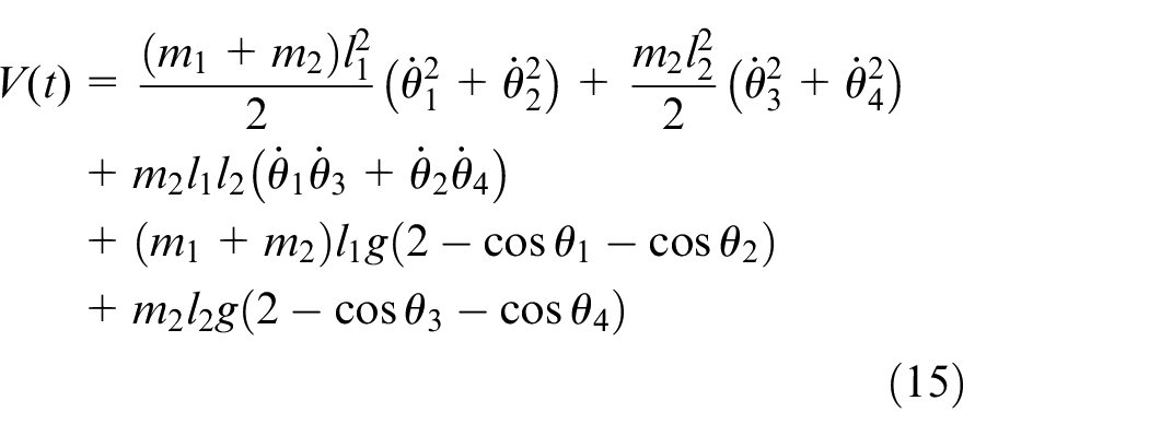
For the arithmetic and geometric inequality of equation (15), the following conclusion can be obtained
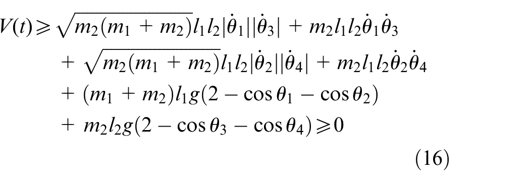
where it is easily obtained that
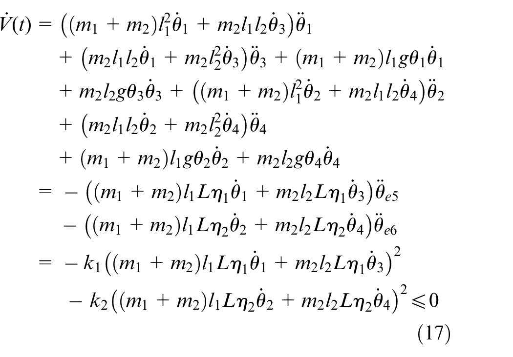
Taking the time derivative of equation (15) and combining with equations (11)–(14), we have
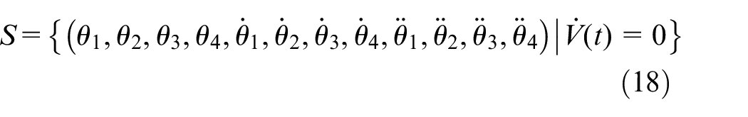
Then, the following invariant and compact set S is introduced to complete the proof
It follows from equations (17) and (18) that
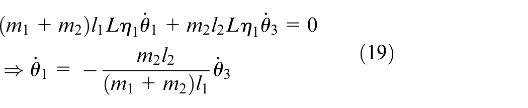

According to equations (19), (20), and the initial conditions for each sway angles and their angular velocities, we have
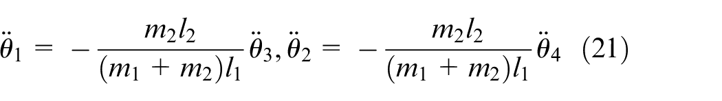
Substituting equations (19) and (20) into equations (13) and (14), respectively, it can be obtained as follows

Further, substituting equations (21) and (23) into equations (7) and (8) respectively, it is clear that
Then, it can be easily obtained

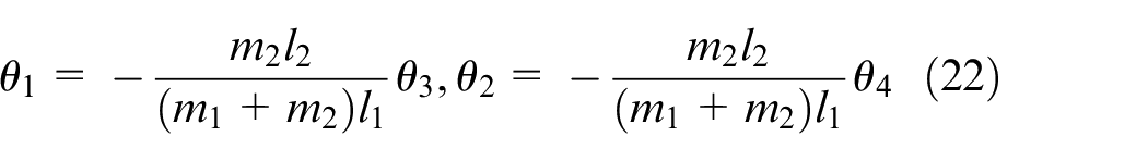
Substituting equations (24) and (25) into equations (21) and (22), respectively, we have

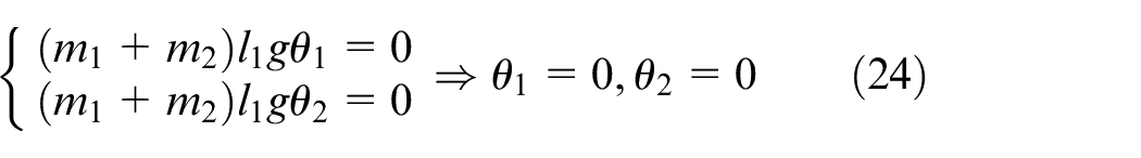
Similarly, from equation (26), it is clear that


Based on the LaSalle’s invariance theorem and the above analysis, there is one and only one equilibrium point in the maximum invariant set M, Theorem 1 is proved, namely
Reference angular trajectory component design
Next, the following smooth S-shaped curve is selected as the reference trajectory for vertical and horizontal boom motion
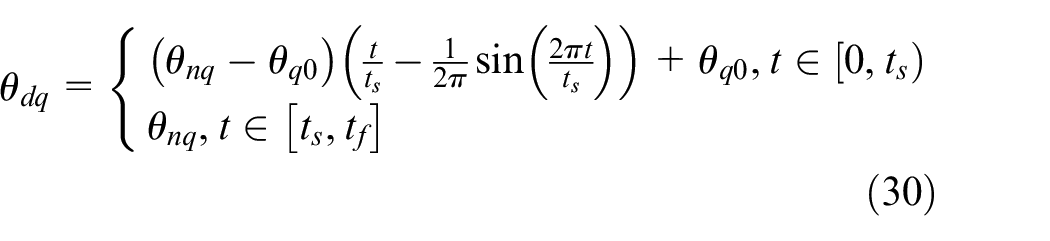
where
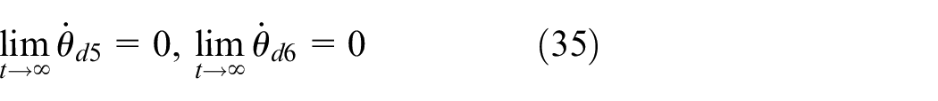
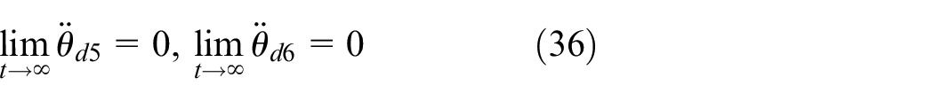
Based on the above analysis, there is one and only one equilibrium. Then, the related reference angular velocity, angular acceleration, and jerk trajectory of the boom are
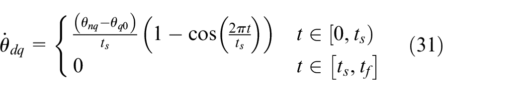
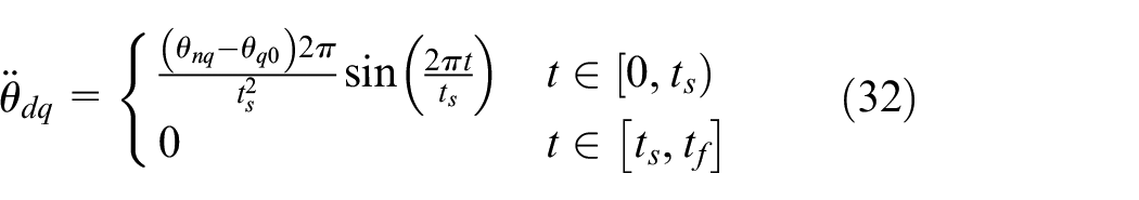
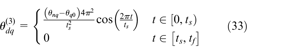
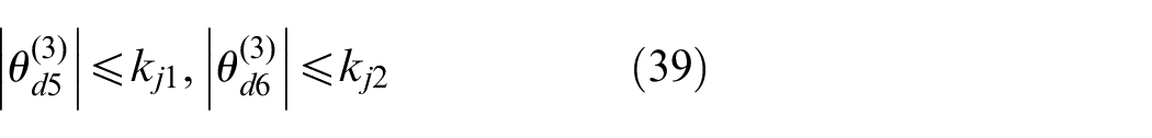
Out of concern for smoothness and precision, the reference angular trajectory we selected should satisfy the following conditions:
The reference trajectory of the vertical boom angle

Then, we can easily get the following conclusions
Besides,


where
The initial conditions are chosen as


Final trajectory analysis
Finally, to eliminate the sways of the hook and the load while the boom accurately reaches the desired position, we construct the following final acceleration trajectories linearly combined by load sway rejection parts and desired angular acceleration trajectories


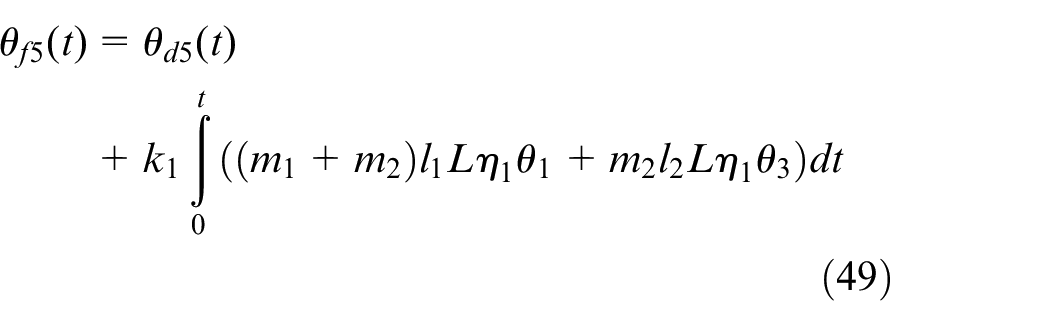
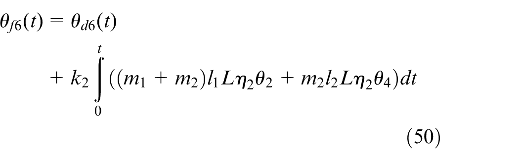
Next, combining equations (13), (14), (42), and (43), the ultimate trajectory can be presented as follows
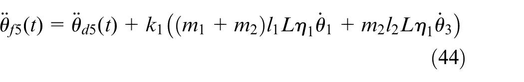
Hereon,
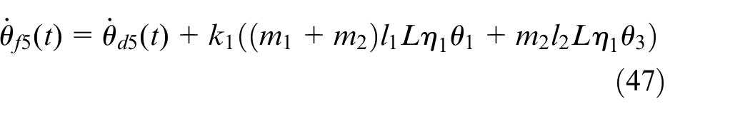
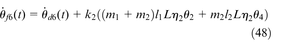
From equations (40), (41), (44), and (45), the final angular velocity and angle trajectory of the boom are
Theorem 2
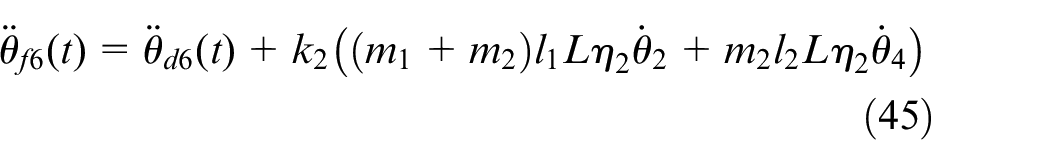
The expected angular acceleration trajectory of the boom

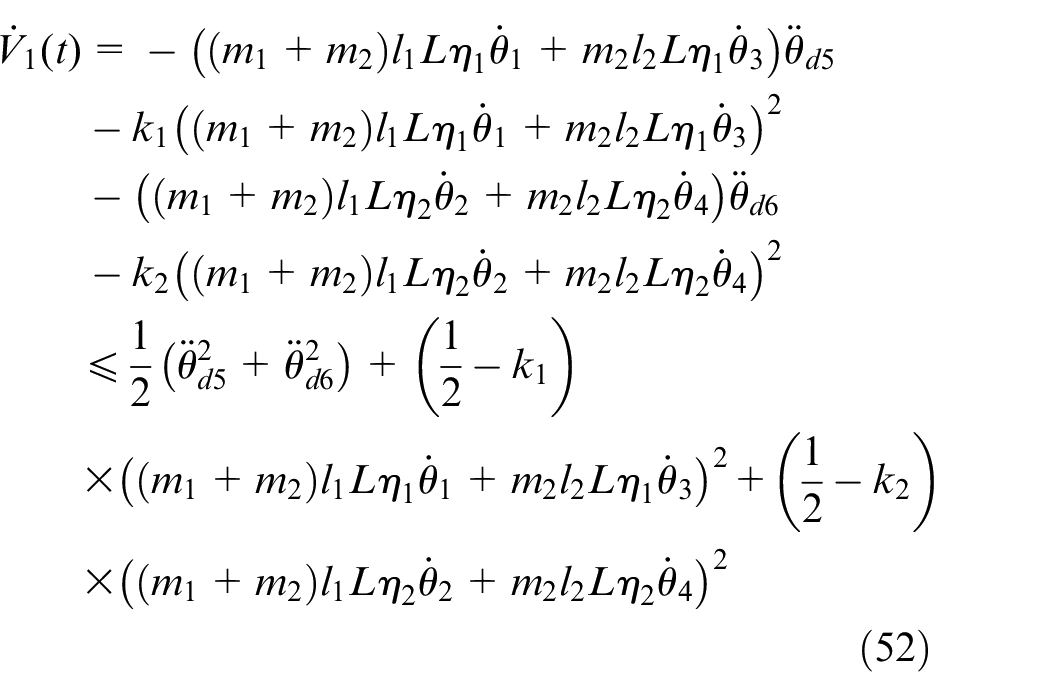
Proof
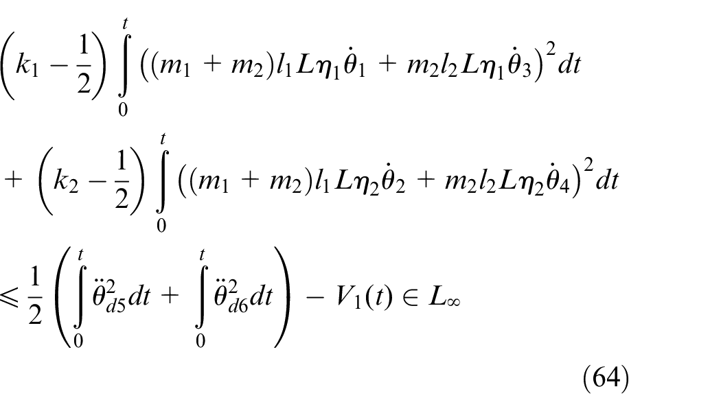
Taking the time derivative of equation (15) and combining with equations (11), (12), (44), and (45), then utilizing the arithmetic and geometricians inequality, the following conclusion can be obtained eventually
By integrating with time at both ends of equation (52), the following result can be obtained
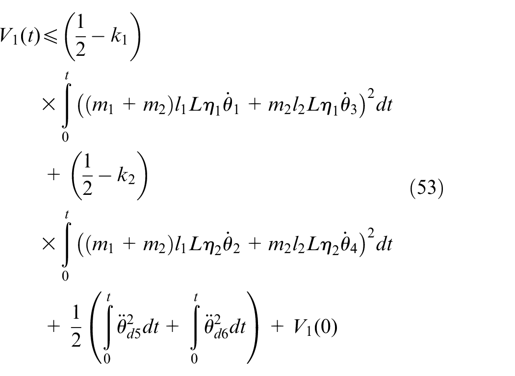
where
Based on the method of integration-by-parts, we have
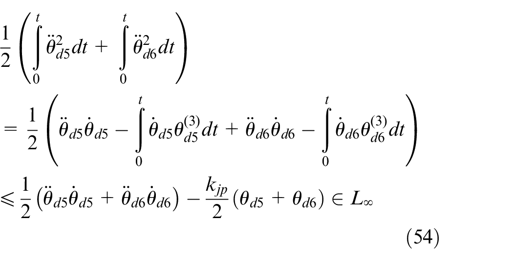
where
From equation (46), it can be easily obtained
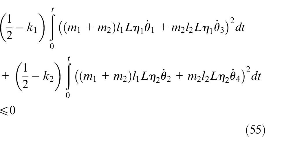
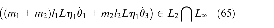
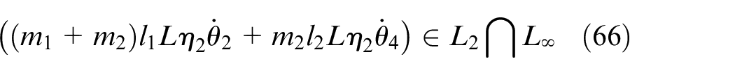
Then, from equation (16) and equations (53)–(55), it is obtained as follows


According to equations (38), (44), (45), and (57)

From equations (7)–(10), it is clear to obtain
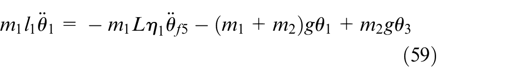
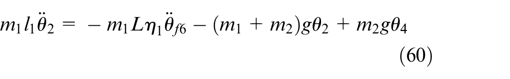


It follows from equations (58)–(62), we have

It is available from equation (53)
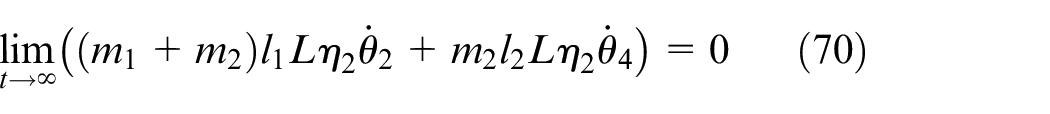
In view of equations (57) and (64), one derives
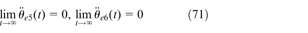
Moreover, it can produce the following results based on equation (63)


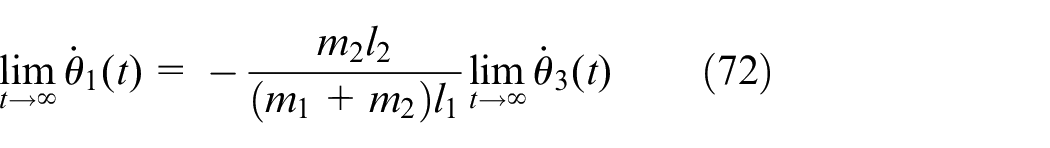
According to equations (65)–(68) and the Barbalat’s lemma yields
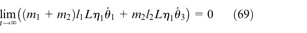
Combining with equations (13), (14), (69), and (70), it is clear that
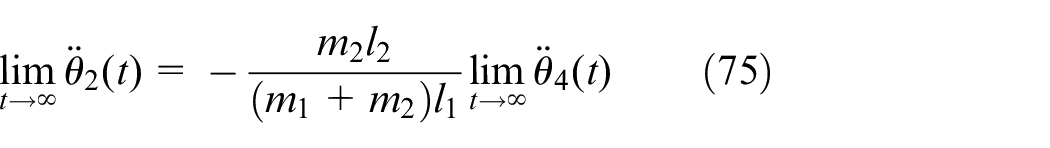
Then, it can be obtained from equations (69) and (70) that

Next, it is available from equations (72) and (73) that

Substituting equations (36) and (71) into equations (42) and (43), respectively, we have
It then follows, using the conclusion of equations (7), (8), and (74)–(76), that

According to equation (77)
Then, from equations (9), (10), (74)–(76), and (78), we can obtain
Similarly, from equation (79), it is clear that
Ultimately, from equations (78) and (80), it is clear that
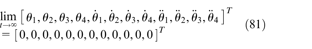
It can be concluded from equations (7)–(10) that


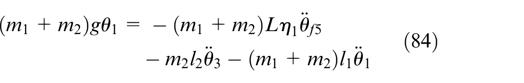
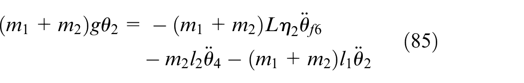
By integrating both sides of equations (82)–(85), it is derived that

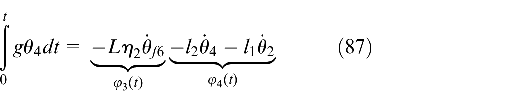

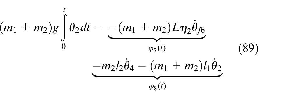
It follows from equations (41), (47), (48), (63), and (81) that
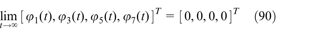

According to the extended Barbalat’s lemma and equations (90) and (91), the following result is obtained
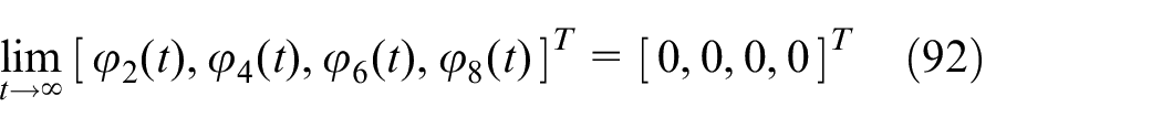
From equations (86)–(91), we have
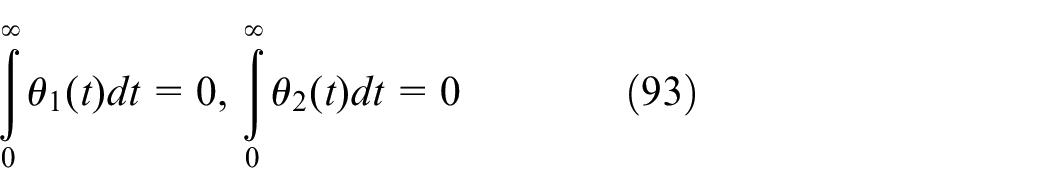
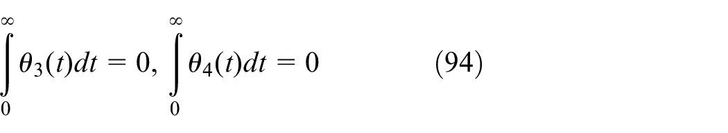
Then, it can be concluded from equations (34), (49), (50), (93), and (94) that
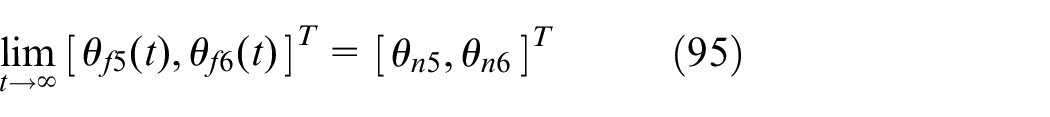
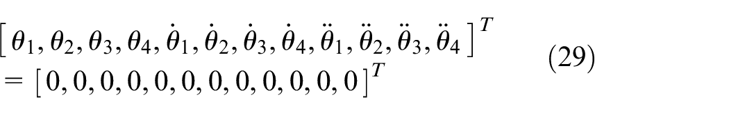
From equation (95), we have
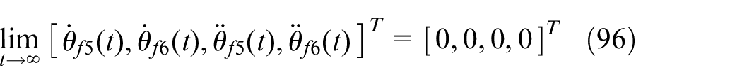
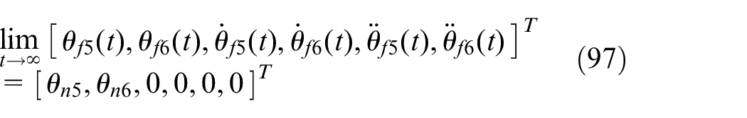
Combining equations (95) and (96) yields
Results and discussion
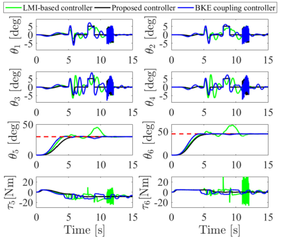
In this section, to verify the superior performance of the proposed control method, we performed a series of comparative simulations and analysis. Specifically, we will illustrate from two aspects of the simulation. The first aspect is to compare with a linear matrix inequality (LMI)-based control method 37 and the boom kinetic energy (BKE) coupling control method. 38 The second aspect is to verify the strong robustness of the proposed method. In this regard, we complete the simulation verification by taking into account different boom reference positions, changing the system parameters, and adding external disturbances.
Simulation conditions
In this paper, we built a simulation platform by using MATLAB/Simulink. The detailed parameters of the crane system are shown in Table 1. After repeated adjustments, the specific sway damping ratio parameters are selected as follows

Rotary crane model.
In all simulations, the initial and reference values of the vertical boom angle and horizontal boom angle were set as
Comparative simulations
For the purpose to verify the superiority of the proposed method, many numerical simulations were performed and compared with the LMI-based control method and the BKE coupling control method. The detailed expressions of the above various controllers are described as follows:
First of all, the LMI-based control law is described as follows

where
Second, the BKE coupling controller can be obtained as follows
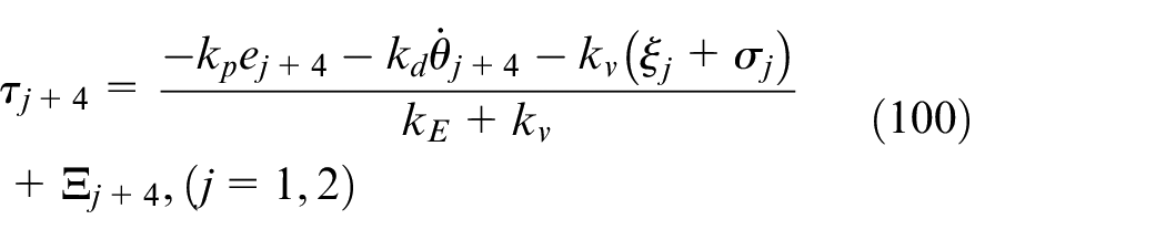
where
The related results for the boom position
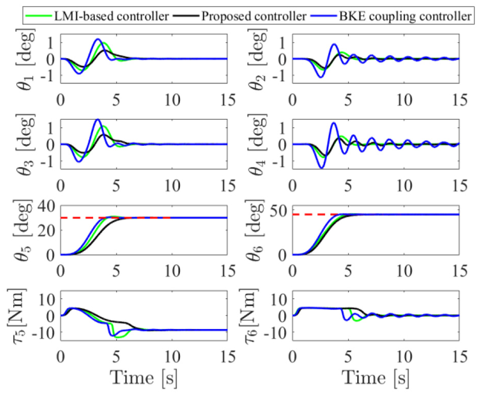
Comparative simulation results.
Quantified analysis results.
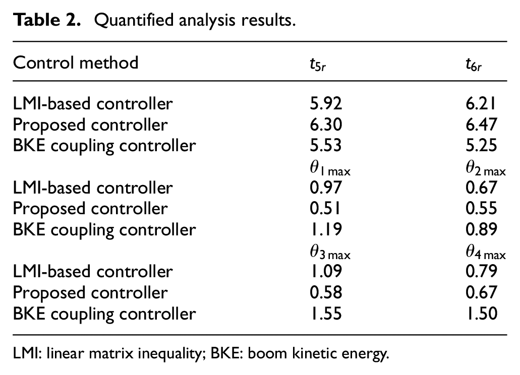
LMI: linear matrix inequality; BKE: boom kinetic energy.
Robust performance
In this part, we conducted four simulations in different aspects to verify the robustness of the proposed controller for double-pendulum rotary crane.
In the case of different desired boom positions and model parameter uncertainties, as shown in Figures 3–5, we first set boom reference position as
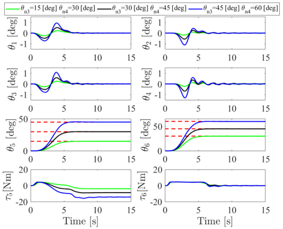
Simulation results with different reference boom position.
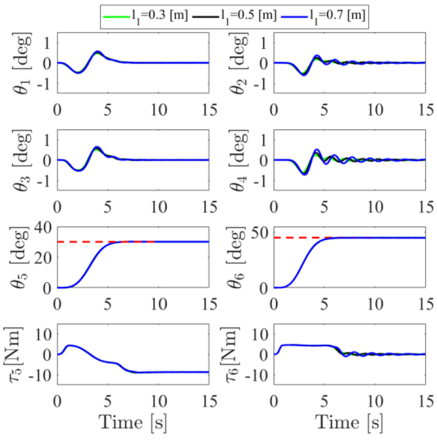
Simulation results with different rope length.
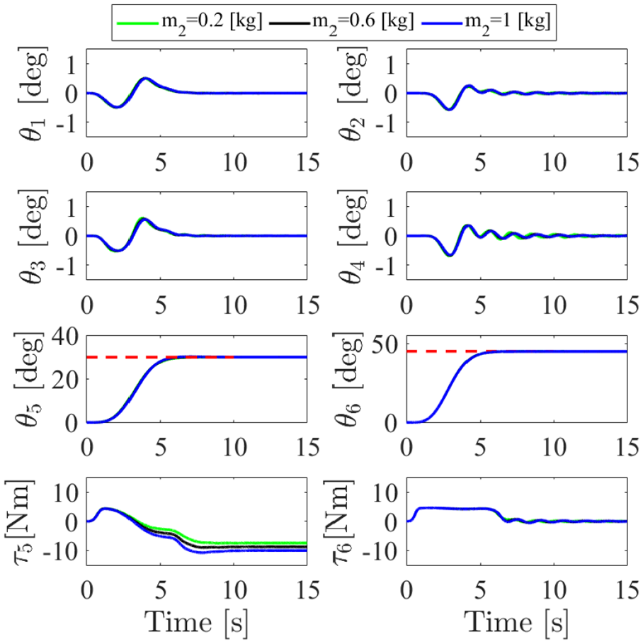
Simulation results with different load mass.
Finally, we added a sine wave signal between 5 and 6 s, a pulse signal between 8 and 9 s, and a random signal between 11 and 12 s with their maximum amplitude 5 deg as swing angle disturbances. Figure 6 shows the simulation results, and in the case of external disturbances, the proposed controller is strongly robust, which will not be affected in positioning and elimination of swing angles performance.
Simulation results with external disturbances.
Conclusion
In this study, an online motion trajectory planning method was proposed to realize both boom positioning and the load sway suppression for the double-pendulum rotary crane. Unlike the traditional approach, the presented trajectory can be calculated online without an accurate model of the crane system. Hence, it has strong robustness to parameter changes and external disturbances. Simulation results demonstrated the effectiveness of the proposed method by comparing with the existing ones.
Footnotes
Declaration of conflicting interests
The author(s) declared no potential conflicts of interest with respect to the research, authorship, and/or publication of this article.
Funding
The author(s) disclosed receipt of the following financial support for the research, authorship, and/or publication of this article: This work is supported in part by the National Natural Science Foundation of China under Grant 61703202, in part by the Postgraduate Research and Practice Innovation Program of Jiangsu Province under Grant SJCX20_0346, and in part by the Jiangsu Provincial Key Research and Development Program under Grant BE2017164.