
Abstract
At present, marine resources, especially the deep-sea resources, are becoming more and more important in resource exploitation globally, and hence, widely used deep-sea cranes are playing essential roles. For such systems, the bridge frames and trolleys are set up above the water, while payloads are transported under the water. In this underwater situation, there exist hydrodynamic forces such as complicated disturbances to the crane systems, making the payload vibration and rope flexibility more obvious. For the sake of improving working efficiency, considering the constraints of all the state variables, an anti-vibration trajectory is designed for the trolley motion, which can not only ensure trolley positioning but also suppress the flexible payload’s vibrations. Then, the state variables are constrained within preset safety ranges. Finally, numerical simulation results prove the satisfactory performance of the designed method.
Keywords
Introduction
In these years, as powerful equipment, cranes have been widely applied in architectonics, nuclear power construction, petrochemical industry, port construction, industrial environmental protection, and so on. Therefore, crane systems1–12 are playing significant roles in modern industry gradually.
According to various practical applications, cranes can be divided into rotary cranes, tower cranes, gantry cranes, overhead cranes, and so on. In the light of the working environment, there are cranes operating on land and under water. Although their specific models and characteristics are different, they all belong to typical underactuated systems with more degrees of freedom (DOFs) than their independent control inputs.13–22 Underactuated systems have stronger nonlinearities with variables being coupled with each other, making it more difficult to analyze and solve their control problems compared with fully actuated systems. However, in terms of energy saving, structural complexity, and cost reduction, underactuated systems are superior to fully actuated ones. Aside from cranes, translational oscillations with a rotational actuator (TORA)23–25 systems and underactuated robot26–28 systems also belong to underactuated systems.
An underwater crane system, as the term suggests, refers to a type of crane whose driving part is set above water with its flexible payload being transported in water. At present, the crane system is greatly used in oil exploration, sea resources exploitation, nuclear reactor, and other fields. In view of the flexible payload and high-precision requirements, the crane’s control objectives are to rapidly and precisely transport the payload to the preset position and also effectively restrict the vibration of the payload throughout the entire transportation process, bringing about zero residual vibration at the end of the process. There are two obvious problems that need to be addressed during the payload transportation. On one hand, the vibration of the payload under water will be influenced by the amplification of the hydrodynamic force compared with the one on land, which may cause large-amplitude vibration. On the other hand, in practice, cranes need to be manually operated by operators who are experienced and skilled, but minor operational mistakes caused by manual operation are inevitable, thus increasing the possibility of accidents. Consequently, considering the above two problems, it is demanded to devise a control approach to realize the goal of instantly reaching the desired position and effectively suppressing the residual vibration of the flexible payload simultaneously.
The underactuated systems’ control problems have been studied in academia, and many researchers have made remarkable achievements in recent decades. At present, the two most common existing methods are open-loop control strategies and closed-loop control methods. Specifically, open-loop control strategies include trajectory planning, 29 input shaping,30,31 and feedforward control. 32 For closed-loop control, there are also many representative approaches such as sliding mode control,33–35 fuzzy control, 36 model predictive control,37,38 and feedback linearization.39,40 In different application scenarios, these two kinds of methods have their respective advantages.
In fact, in some applications, crane systems exhibit complex flexibility; for instance, when the overhead crane uses a flexible cable for payload transportation, the cable exhibits the characteristics of a flexible cord. 41 Recently, the control of flexible systems on land has attracted much attention in the control and mechatronics society. For example, in He and Ge, 41 cooperative control laws are put forward to limit the flexible cable’s deflection. Based on the dynamic model, a singular perturbation method is applied in Peng et al. 42 to control the coupling system. Then, in He et al., 43 a hybrid system is obtained and a well-designed controller is proposed to eliminate vibration. Next, in Xie et al., 44 a smoother is proposed to reduce the flexible payload’s vibration by command smoothing, which achieves vibration reduction of multi-mode systems. Also, in Fatehi et al., 45 two effective controllers are designed on the basis of the singular perturbation method to regulate the crane system with large swing.
The exploitation about marine resources, especially the deep-sea resources, is gradually becoming an increasingly important resource developing trend around the world. As a sequel, deep-sea crane systems are widely applied to exhibit important research values. However, there are few published works on the topic of underwater transportation control. The aforementioned existing methods are designed for flexible systems operating on land without considering underwater situations, which bring much stronger flexibility and are much more challenging. Until now, the research on underwater flexible crane systems is still open. For such systems, the hydrodynamic force will bring larger deflection in the flexible payload under water than on land, that is, producing greater flexibility, causing the payload to vibrate severely, and making the system exhibit much more complicated nonlinear characteristics during transportation. Furthermore, regarding sensors, it is extremely uncertain whether they function well or not in water. Hence, compared with cranes working above water, it is more difficult to achieve precise and efficient transportation for flexible systems in underwater situations. There are some studies about the flexible payload immersed in fluids. For instance, in Shah et al., 46 the system model is calculated and a boundary control method is designed to limit the vibration of the rod. Then, in He et al., 47 a robust adaptive control method is provided to deal with the vibration of the controlled object in water. In Zhao et al., 48 a boundary control method is proposed without simplifying the dynamic equations to restrict the vibration of the flexible riser. To reduce the vibrations in both two directions of the fuel rod, a relatively indirect but comprehensive control law is developed in Shah and Hong 49 to regulate the movement of the trolley and the bridge. In Shah et al., 50 considering the constraint of the rod’s deflection range and a similitude law, a modified input shaping method is developed to limit the flexible rod’s residual vibrations.
In this paper, an anti-vibration polynomial-based trajectory planning method without simplifying and linearizing the dynamic model is proposed. On one hand, the method can restrict the flexible payload’s vibration. On the other hand, it can improve transportation efficiency. Specifically, we divide the velocity of the driving device (e.g. trolley) into three segments: the velocity of the first and last segments is symmetrical, and the velocity of the middle segment is the value allowed by the equipment. Next, the satisfactory performance of the designed method is verified by simulation results. In conclusion, the main contributions of this paper are summarized as follows: (1) without simplifying or linearizing the dynamic model, an anti-vibration polynomial-based trajectory is designed, which can not only meet the requirements of payload transportation but also improve the efficiency; (2) a function
The paper is organized as follows. First, in section “Problem statement,” we provide the system model and then summarize the problems to be solved by analyzing the control objective and for the purpose of improving transportation efficiency. Next, in section “Anti-vibration trajectory planning method,” a new planned trajectory, which is designed by planning the trolley’s velocity, is used for this system, and the effectivity of the designed trajectory is verified by numerical simulations. Finally, in section “Conclusion,” we present a summary about the major work of this paper.
Problem statement
Because of the underactuated characteristic of the deep-sea crane system, the vibration at the end point of the payload cannot be directly controlled. In order to ensure accurate and rapid trolley positioning and to suppress the payload’s vibration by constraining the maximum vibration amplitude within a given range, the coupling relationship among state variables must be fully utilized to plan the control input, that is, the acceleration. Furthermore, considering the practice factors, the state variables should meet some specific constraints.
System model
Figure 1 shows a two-dimensional (2D) schematic diagram of the underwater crane system, where in the inertial coordinate
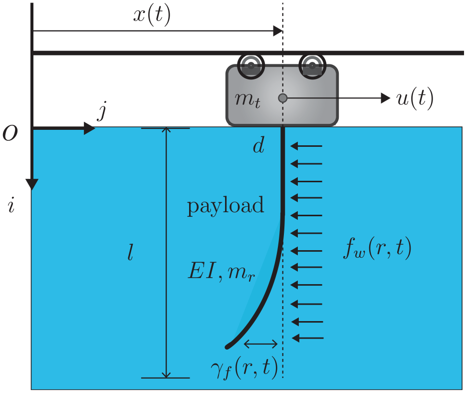
The flexible crane system in water.
Let
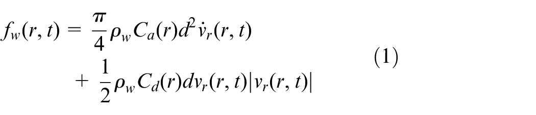
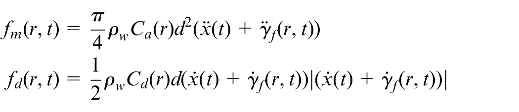
where

where
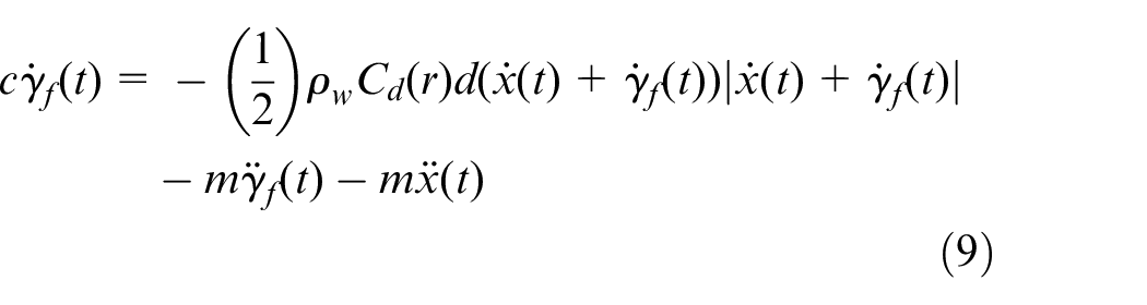
In light of Shah et al., 50 the dynamic model of the system is given as follows
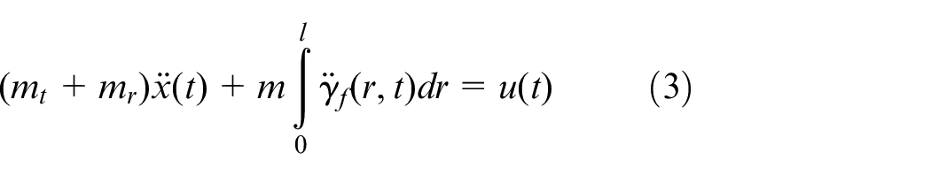
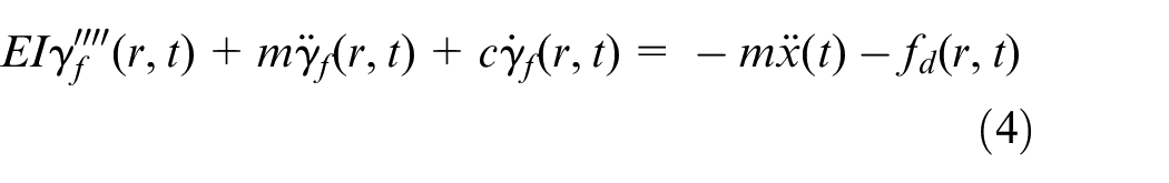
where
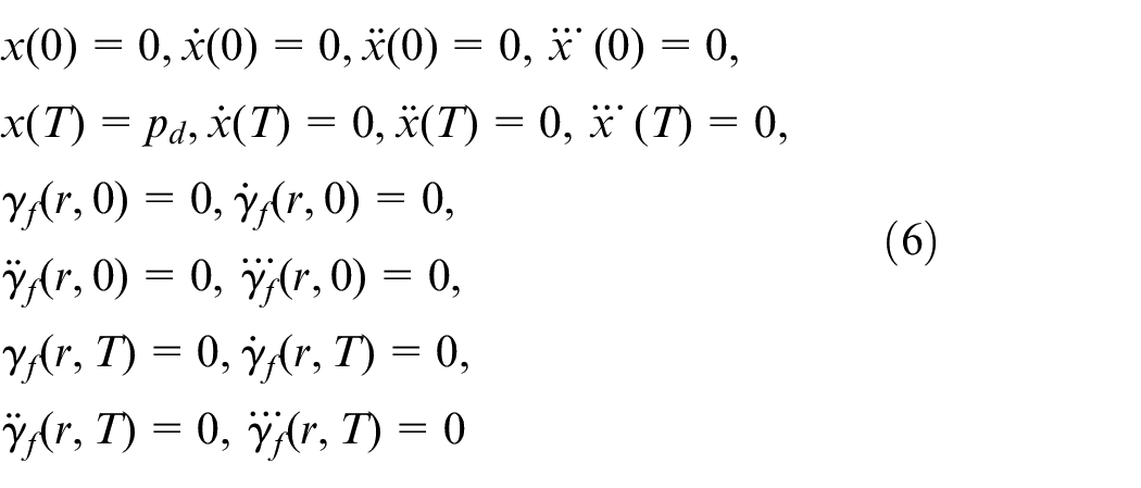
Then, we set the following boundary conditions

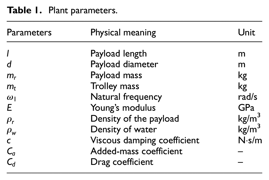
For the sake of distinction, let
Plant parameters.
Control objective
Considering the actual operating environment of the deep-sea crane system, the control objective can be described as follows:
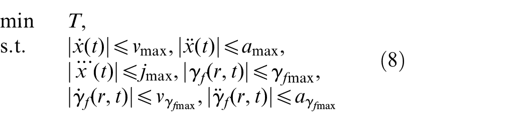
The time to complete the entire transportation process is defined as
Based on hardware restrictions and safety concerns, the state variables, that is, trolley velocity, payload deviation, and so on, should be reasonably limited within a suitable range during the entire transportation process. Therefore, the variables should satisfy the following constraints
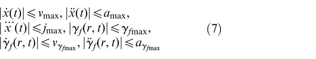
where
The optimal time under certain conditions
To improve the efficiency of the system, the value of
Anti-vibration trajectory planning method
For the purpose of simplifying the calculation, only the deviation value of the end point of the flexible payload is considered. According to the practical situation, if the vibration of the end point of the payload meets the requirements, the vibration of the other points must also be within the allowable range. Hence, this paper only considers the state of the end point, which can equivalently capture the state of the entire payload. At this point,
From equation (9), we construct a signal

By substituting equation (10) into equation (9), one has that
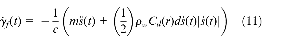
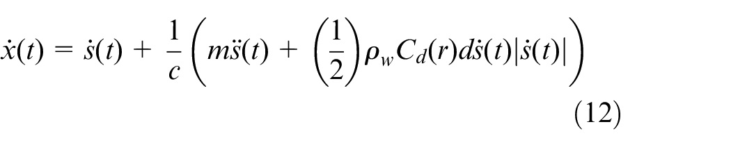
After that, all state variables can be represented by the signal
Trajectory planning
If the velocity of the trolley can reach the maximum value within a limited time and last for a while, the running time will be further shortened and the transportation efficiency will be improved compared with the single-peak velocity trajectory, which is a trapezoid velocity trajectory containing three curve segments (increasing velocity, constant velocity, and decreasing velocity). The maximum velocity of the trolley can be obtained based on the limit range of the deflection, that is, it is feasible to plan the trajectory of the trolley’s velocity.
To realize the control objective, the velocity is divided into three segments, and the acceleration can be guaranteed to be continuous. The first segment is designed as a polynomial from

First, to obtain the velocity of the first segment,
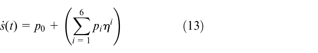
where
The partial equality constraints of
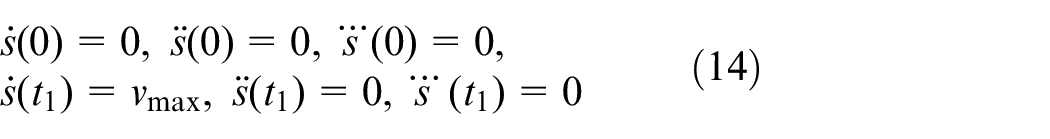
By substituting equation (14) into equation (13), the following equations and coefficient relationships can be obtained
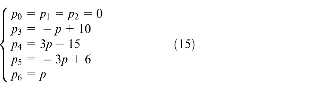
After that, we let
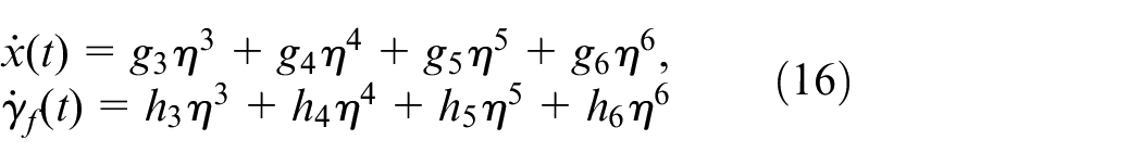
Then, the constraints of
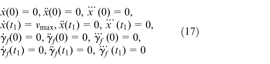
By substituting equation (17) into equation (16), the coefficient relationships can be rewritten as follows
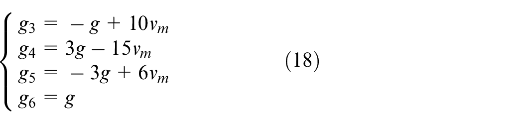
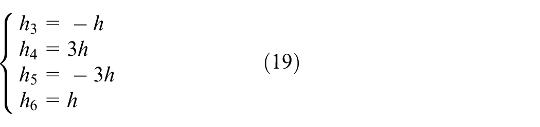
Actually, if the initial values of any two of the three parameters are given, we can then obtain the value of the last parameter. Specifically, from equations (10), (13), (15), (16), (18), and (19), we can derive that
So far, the first velocity expression containing an unknown parameter
To do so, we use the dichotomy to solve the problem in equation (8) and obtain the optimal time. The pseudocode is given in Algorithm 1, where
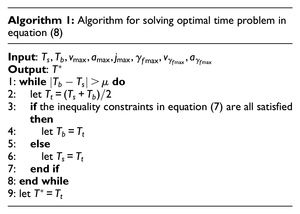
Based on equation (7),
Numerical simulation results
To obtain the deflection values of the flexible payload based on the trolley movement, the finite difference method (FDM) is applied to solve the partial differential equation (PDE) in equation (4). For the simulations, the parameters are set as in Table 2, which are from Shah et al. 50
System parameters.
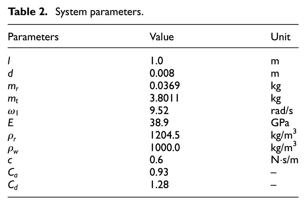
Figure 2 indicates the simulation results of the planned anti-vibration trajectory with
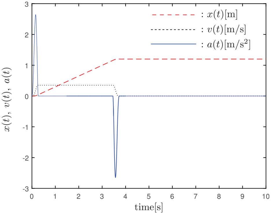
Displacement, velocity, and acceleration trajectories of the trolley.
For the purpose of verifying the effectiveness of the planned trajectory, the paper compares the trajectory planning method with the existing input shaping method in Shah et al. 50 The corresponding simulation results are shown in Figure 3. Compared with the input shaping method, what we can see from Figure 3 is that the transportation time of the anti-vibration trajectory planning method is shorter. Therefore, in terms of transportation efficiency, the proposed trajectory planning method is better than the input shaping method.
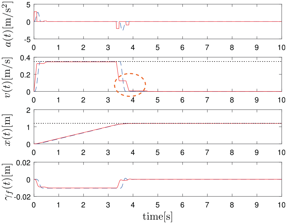
Results of the proposed and comparative methods.
Besides, for the input shaping method, it is noticed from Figure 3 that the trolley acceleration, which is the system’s control input, will suddenly change at some point, that is, the driving force will change suddenly. By contrast, this phenomenon is avoided by the proposed method, which is smoother. Moreover, compared with existing methods (e.g. input shaping method), the proposed method ensures that the accelerations are continuous and also protects the actuators in practice.
Figure 4 is a three-dimensional (3D) diagram of the deflection of each position of the flexible payload with respect to time using the anti-vibration trajectory planning method, and it reflects the vibration response of the entire flexible payload to the velocity command.
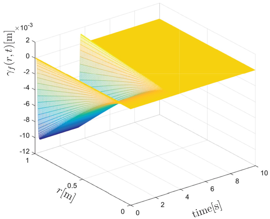
Three-dimensional diagram of the anti-vibration trajectory planning method.
Conclusion
In this paper, with no linearization to the dynamic model, a new anti-vibration polynomial-based trajectory planning method is proposed, which considers the constraints of all state variables while achieving the control objective. The design of the anti-vibration trajectory is to divide the velocity into three segments and make the trolley move at the maximum velocity for longer time, which improves the transportation efficiency greatly. In the end, simulation results verify the performance of the proposed method. In the near future, we will implement hardware experiments for further verification, and other types of trajectories will also be considered apart from polynomials.
Footnotes
Declaration of conflicting interests
The author(s) declared no potential conflicts of interest with respect to the research, authorship, and/or publication of this article.
Funding
The author(s) disclosed receipt of the following financial support for the research, authorship, and/or publication of this article: This work was supported in part by the National Natural Science Foundation of China (Grant Nos U1706228 and 61873134) and in part by the open project of Industrial Robot Application of Fujian University Engineering Research Center, Minjiang University (Grant No. MJUKF-IRA201801)