
Abstract
Pressure is a key unit of measure in aerospace industries. Spontaneous precise measurement of pressure has to be compassed at locations where it is futile and impractical to couple the pressure responsive constituent to the conditional electronics or computational circuit by practicing standard cables and measurements prone to harsh environment. This paper introduces the design of a wireless pressure-monitoring system for aerospace applications in harsh environment. Traditionally, applied pressure deflects a delicate silicon diaphragm, altering the capacitance developed between it and metal electrode firm on a substrate. The LC circuit translates the pressure variation into the LC resonant frequency shift. This change is sensed remotely by virtue of inductance coupling, expelling the compulsion for wire connection rooted telemetry circuits. Novelty of our work rests in the fact that contrary to examining shift in the resonant frequency due to the applied pressure, we have put in effort to maintain resonant shifting equal to zero by varying the capacitance at the observer unit. This will allow pressure variations to be measured directly in terms of the capacitance variation at a fixed resonant frequency, which is 7.92 MHz in our context. According to the application domain (avionics), the proposed sensor structure is designed for functioning in the pressure range between (100 and 1140) mbar. The choice of design values for sensor parameters has been validated. The sensitivity is measured to be 1.746e−17 F/Pa over specified linear range which is shown to match a theoretical estimate realized by mathematical model. An in-depth, step by step derivation of performance parameters to achieve above-stated objective is shown for sensor under study. The results generated are modelled and examined using MATLAB. The analysis conducted dovetail perfectly with the modelled results.
Keywords
Introduction
For a few but prominent industries such as aerospace, automotive and biomedical applications, a pivotal entity for calculation in a system is pressure.1–3 Accurate and instantaneous determination of pressure is essential at remote locations where it is impossible to plant a measurement circuit by using recognized cable links. Accordingly, an integrated passive sensor capable of measuring pressure in severe environments such as high loading or high temperature is usually desired.4,5
Wireless passive sensors are one of the major sections in plenty of non-contact measurement applications. 6 One of the elementary varieties of wireless passive sensors is an inductive coupling resorted LC resonator.7,8 Standard quality factor Q of this type of resonators is around 40. 9 By the reason that an LC passive pressure sensor does not require an internal power supply and a wire link, they have been extensively employed in some specialized applications. 10 Few of the industrial applications of the LC resonator–based sensor involve the systems for non-contact structural monitoring of concrete structures, sensing of intra-ocular pressure, pH monitoring, measurement of humidity, patient health monitoring, bio-potential measurement and strain monitoring of automobile tyre. 7 A conventional wireless passive LC sensor system has two magnetically coupled coils. One of the coils, named as sensor coil, is allied to a capacitive sensor and forms an LC tank circuit, whereas the second coil, called as observer coil, is electrically linked to a measurement circuit. The resonance frequency of the tank circuit is a function of variation in capacitance of the capacitive sensor. The external pressure results in the change of capacitance, so the sensor’s resonant frequency alters. The value of applied pressure can be estimated from the frequency that can be remotely detected by another inductively coupled coil that is connected to the measurement circuitry. 11 Most of the existing methodology identifies the corresponding shift in resonance frequency utilizing suitable readout electronics and an impedance analyser.
Micro-electromechanical system (MEMS) capacitive pressure sensors are favoured for less weight, low cost, more reliability, smart functions, occupies very less space, low-power and telemetric applications since they never draw DC power and efficiently form passive inductor-capacitor (L-C) tank circuits for frequency-based measurement of pressure. Micromachined capacitive pressure sensors typically use an elastic diaphragm with fixed edges and a sealed cavity in between the diaphragm and the substrate below.12–14
This research explores a capacitive pressure sensor that consists of two micro machined metal plates with a gap depth. The capacitance change on application of pressure can be interrogated by varying the capacitance at the observer unit, keeping resonant shift constant. As always, the tank can be formed by coupling an inductor coil with the sensor separately, or it can be done by winding an insulated wire directly on the sensor. The wireless interrogation can be implemented using an inductor that is magnetically coupled with the L-C tank device. This paper is constituted as follows. Section ‘Transduction mechanism of capacitive pressure sensor’ describes the transduction mechanism of capacitive pressure sensor. The details of the design of sensing unit are presented in section ‘Design of sensing unit’. Section ‘Circuit design for Si wireless module at observer unit’ deals with circuit design for silicon wireless module at observer unit. The simulation results are evaluated in conjunction with the theoretical analysis in sections ‘Sensitivity – major performance parameter’ and ‘Design specifications and considerations,’ followed by discussion in section ‘Preliminary investigations by simulations and interpretations’. Section ‘Conclusion and future work’ concludes the overall effort.
Transduction mechanism of capacitive pressure sensor
The sensor depends upon the applied pressure which alters the distance separating the two electrodes, resulting in change of capacitance as shown in Figure 1. The clamped edge circular diaphragm used here operates as a capacitor with air as dielectric between them. Typically, bottom electrode is fixed and upper electrode is movable. The fundamental design comprises one silicon15,16 membrane acting as movable electrode and another thin film electrode glass plate acting as a fixed electrode.17–21 Electrodes are distant by a small gap which admits membrane deflection. Even in harsh environment, 22 the capacitance variation is sensed precisely and is allowed wireless transmission using an inductively coupled tank circuit having inherent resistance due to the inductor. According to the application field (avionics), the proposed sensor structures are designed for operating in the pressure range of (100–1140) mbar. This capacitance-based pressure sensor shows high linear pressure measurements which are important for avionics applications. 23
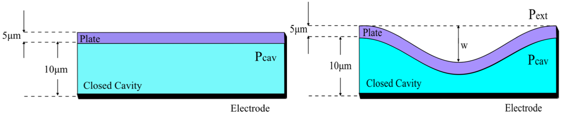
Clamped edge circular diaphragms with thickness 5 µm each and air gap of 10 µm working as a capacitor (left) under no pressure (right) under pressure.
Design of sensing unit
The overall pressure sensing unit primarily has two aspects. First is pressure to deflection measurement and then deflection to capacitance measurement.
Pressure to displacement variation
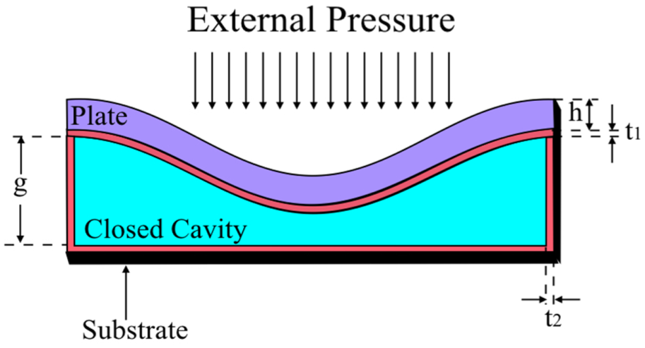
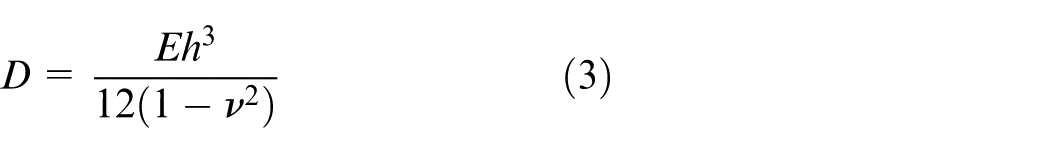
Under consideration is diaphragm as a uniformly loaded circular plate with thickness h. Young’s modulus E and Poisson’s ratio ν are the mechanical properties of the plate (Figure 2).
Mechanical capacitive principle of variable capacitor.
The geometry of the structure and the material properties of the MEMS capacitive pressure sensor for the deflection w(r) of an edge-clamped deflectable diaphragm under an applied pressure as a function of radius for (0 < r < a) is given by equation (1) 14
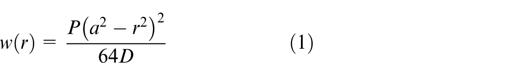
where P is the applied pressure, a is the radius of the plate and r is the radial distance from the centre. At centre point of the plate the maximum centre deflection w0 occurs, that is, at (r = 0) and is given as follows 14
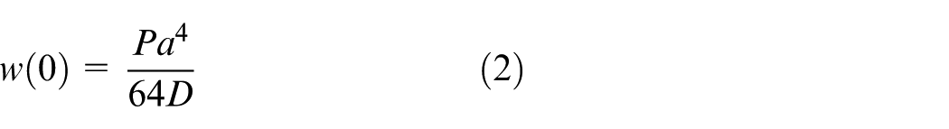
where D is the flexural rigidity of the plate
Analytical capacitance modelling and calculations
Next to deflection of diaphragm is measure of equivalent capacitance variation between the two electrodes of the sensor. We know that the basic equation for capacitance of a parallel plate capacitor is given as 22
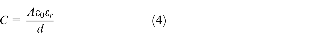
where A is the area of circular parallel plates, d is the separation gap between the plates,
On application of pressure, deflection is produced on the upper plate, which in turn decreases the gap between the clamped diaphragms. The capacitance change is proportional to the variation in the applied pressure which directly is a measure of change in the gap from d to d − w(r,

The total capacitance due to the applied pressure can be calculated by integrating the area from r equal to 0 to radius and R and θ equal to 0 to 2π which is
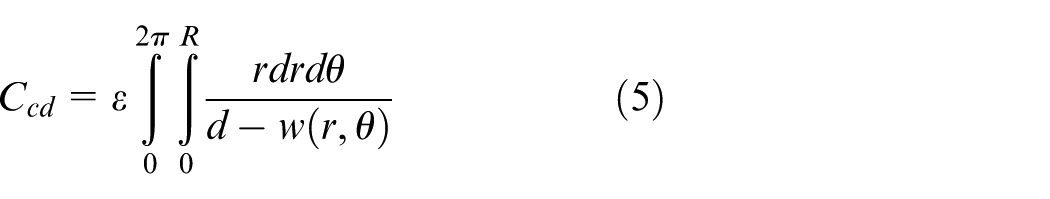
Since the deflection on the diaphragm does not affect by the angle changes,
which can be further solved to get the following expression
Equation (7) shows the deflection to capacitance relation in terms of applied pressure, separation gap and flexural rigidity. The challenge here is the calculation of relative capacitance change, that is, changes in the capacitance relative to the capacitance obtained at zero applied pressure condition. With the mathematical formulation above, the obtained capacitance for the above clamped diaphragm geometry at zero pressure is 0.174 pF.
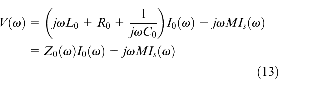
Circuit design for Si wireless module at observer unit
An LC sensor is typically designed from a spiral inductor linked with a sensing capacitor, forming a resonant LC tank. The capacitor changes in response to the parameter of interest, resulting in a shift in its resonant frequency. As an extension to the well-known literature, a new concept has been formulated, simulated and interpreted for pressure sensing. The sensor is modelled with an inductor L and a series resistance of the inductor R and a variable capacitance C. The resonance frequency of the sensor is given as follows 7
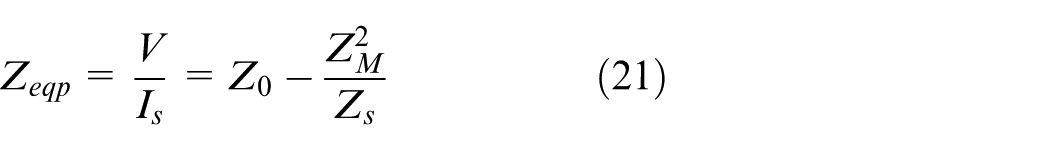
Equivalent impedance for circuit leads to the inductance value of L = CR2. A schematic representation of the typical LC sensor is exhibited in Figure 3 (left), and the corresponding equivalent impedance circuit is shown in Figure 3 (right).
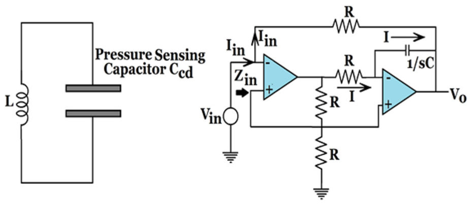
(Left) Simple LC circuit containing pressure sensing capacitor. (Right) Equivalent impedance of circuit leads to simulation of inductor-gyrator.
Instead of single tank circuit, inductively coupled tank circuit is used for wireless operation of the proposed design at the observer unit. The change in the resonant frequency occurring due to fractional change in capacitance in response to applied pressure is detected remotely by use of external coupled circuit called the observer unit. Using inductive coupling, the external coil energizes the sensor circuit which supplies load impedance that is reflected back to the impedance coil. Reflected impedance of coupled circuit is used for the wireless transfer of impedance of sensor unit to observer unit. Since there is no pre requisite of power source and wire connection in the sensing unit, the proposed design can be used in harsh environment with high reliability.
Working principle and mathematical analysis
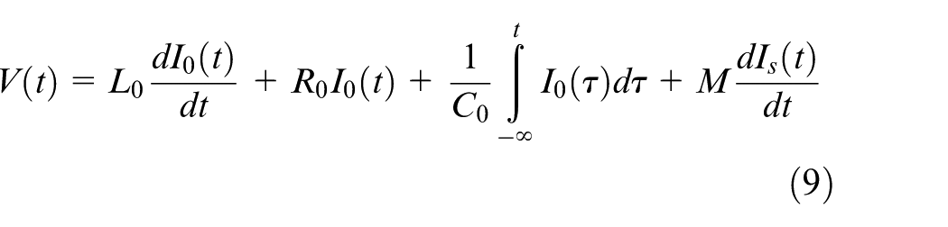
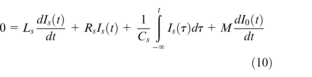
The practical method to sense the capacitance change due to applied pressure through inductively coupled arrangement is shown in Figure 4. Let Cs be the capacitance of the prime sensor on zero applied pressure. The air gap between the upper and lower diaphragm plate is 10 µm. At zero applied pressure, no deflection occurs and sensors initial capacitance is 0.174 pF. Theoretical resonant frequency of sensor at zero pressure is 7.92 MHz. Traditionally, when the sensor is under pressure, the capacitance changes and thus the sensor’s resonant frequency also changes which can be registered with the reader unit. Researcher here has proposed the idea – what if we make shifting of resonant frequency equal to zero by varying capacitance at the observer unit? By and large the sensing unit experiences change in capacitance as soon as pressure is applied on upper plate of sensing capacitor. This induces a change in capacitance resulting in shift in of resonant frequency from 7.92 MHz. We have tried to work out a strategy to get back this change in resonant frequency to 7.92 MHz by varying capacitance at the observer unit. This allows us to directly sense the applied pressure in terms of capacitance at primary observer unit-wirelessly. The proposed methodology is in complete agreement for sensing of applied pressure in range of (100–1140) mbar used for avionic applications. Simulation results in section ‘Preliminary investigations by simulations and interpretations’ aid to novelty above.
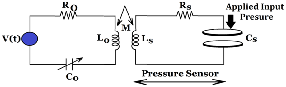
Electrical representation of the wireless measurement set-up with the L-C tank device illustrating both sensor and observer unit with inductively coupled coils
For the design in Figure 4, the integral differential equations are as follows
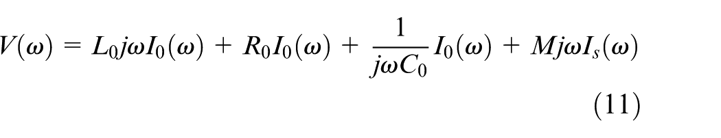
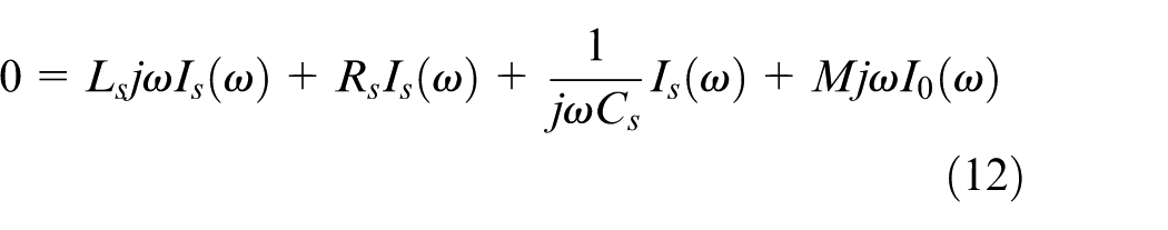
Manipulating the above two equations in frequency domain and on proceeding with Fourier transform with initial conditions to be zero is given by
Conversely
In general
for i = ‘o’ and ‘s’, that is, observer and sensing units, respectively
Further solution for
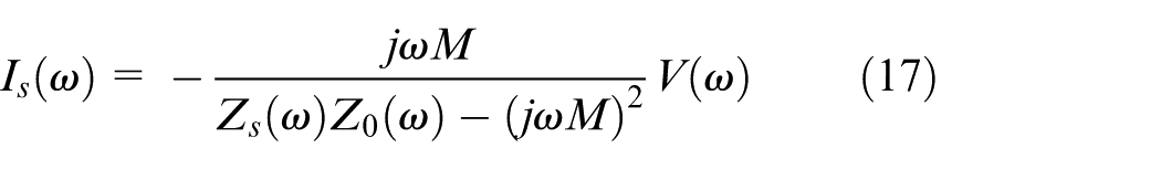
From equations (16) and (17), one can state that resonance occurs at two frequencies.
For zero pressure condition;
For getting resonant frequencies by accrediting the denominator equal to zero in equations (16) and (17), we obtain
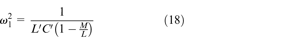
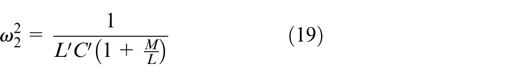
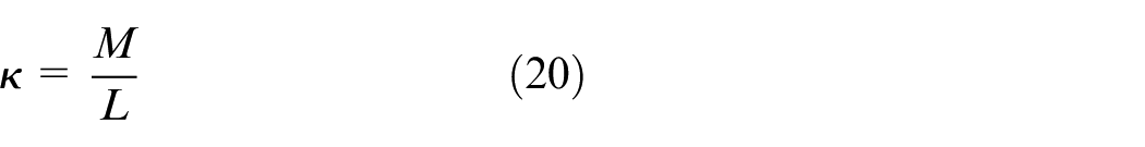
where equation (20) is the coupling coefficient. 24
In contrast to simple tank circuit, here we achieve two resonant frequencies shifted by a measure of
where
Sensitivity – major performance parameter
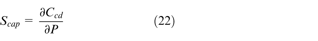
Capacitive sensitivity
Capacitive sensitivity of the capacitive pressure sensor can be defined as the ratio of change in capacitance to the fractional change in the applied pressure, numerically defined as
This ultimately leads to
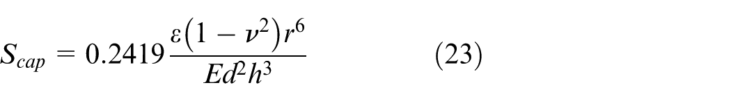
For the proposed design, capacitive sensitivity is calculated to be 1.746e–17 F/Pa which is desirable for MEMS design for application under consideration.
Mechanical sensitivity
Mechanical sensitivity is defined as the ratio of deflection of diaphragm obtained with respect to applied pressure, that is
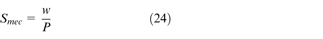
Using the parameters and working out the expression lead to
Design specifications and considerations
First, the outline dimensions are defined. Within the given frame, the cavity supporting structure is constructed. The geometry confided upon the necessary pressure range to be sensed and provided assembling settings. In most cases, a sensor for high-pressure sensing necessitates rigid supporting structure. When the membrane size is decided, the gap is figured out first from the mathematics of capacitor calculation, and then a simulation is performed using the proposed geometry. The design is optimized using simulations. To mention, an MEMS capacitive pressure sensor (as shown in Figure 2) with 10-μm air gap, 250-μm membrane radius and 5-µm electrodes/membrane thickness has been selected for primary sensing.
The tank is built by coupling an inductor coil with the sensor independently; else, it can be formed by winding an insulated wire precisely on the sensor as shown in Figure 5. The wireless interrogation can be realized utilizing an inductor that is magnetically coupled with the L-C tank. Specification for design of sensor is summarized in Table 1.
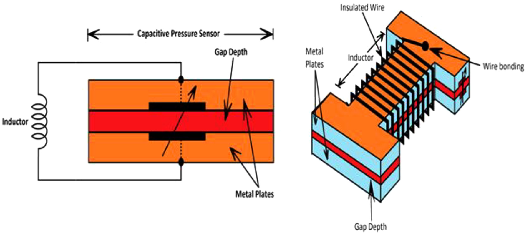
MEMS capacitive pressure sensor with L-C tank arrangement for capacitance-based pressure detection. (Left) Cross-sectional view of the sensor coupled with a separate inductor. (Right) Device with an inductor wound on the sensor.
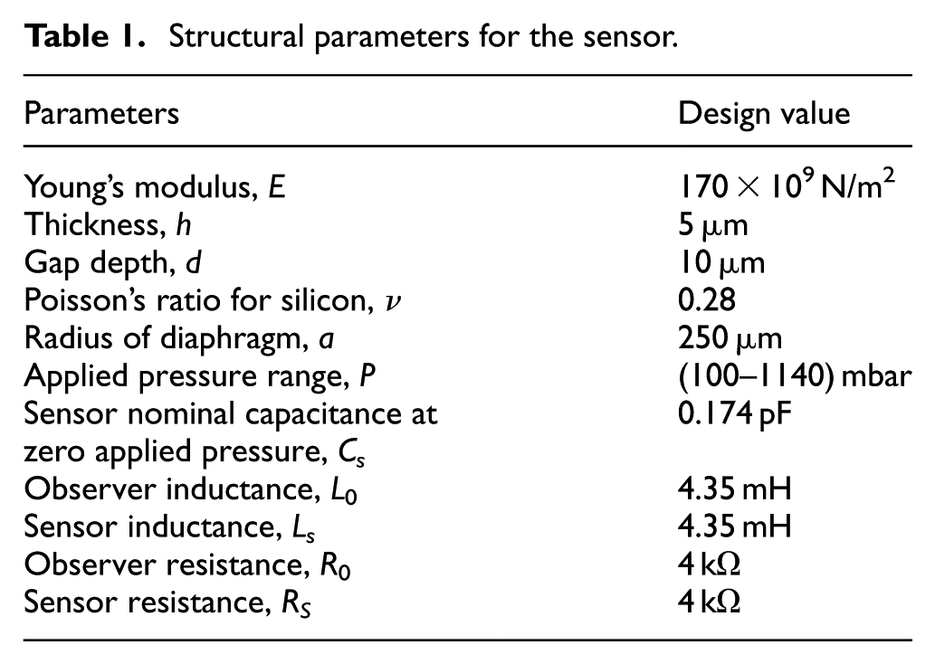
Structural parameters for the sensor.
Preliminary investigations by simulations and interpretations
In Figure 6, variation of surface deflection with radius of circular diaphragm is investigated at a pressure of 0.5 bar. Equations (1)–(3) are used to simulate this result. Performance is investigated for P = 0.5 bar, r = 180 µm, E = 170 × 109 N/m2 and ν = 0.28. It is observed that diaphragm deflection is maximum at the centre and is equal to 0.2 µm and it decreases as radius increases. The data belong to the sensor side. The variation of surface deflection with radius of circular diaphragm is compared with work done in Jindal et al. 14 The comparison of proposed design with stated cross-reference is valid since the value of structural parameters has been taken from previous works.14,21 Deflection of the diaphragm in both the schemes increases initially till it reaches a peak and then settles down gradually as radius of diaphragm increases.
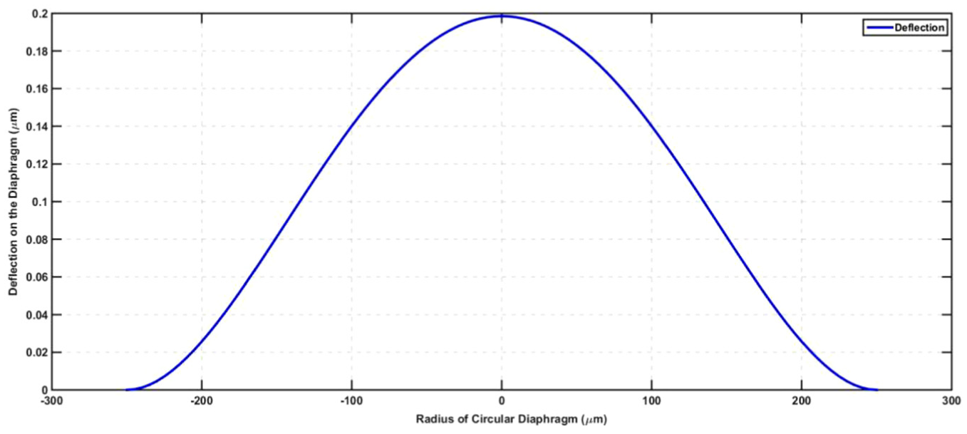
Variation of surface deflection with radius of circular diaphragm at a pressure of 0.5 bar.
In Figure 7, relative capacitance change for the designated pressure range, that is, 0.1–1.14 bar is under investigation. Equation (7) is used to simulate this result. Performance is investigated for P = (100–1140) mbar, r = 180 µm, E = 170 × 109 N/m2 and ν = 0.28. Zero pressure capacitance is observed to be 0.174 pF. It is evident that capacitance variation is near about linear. Hence, it can be interpreted that proposed methodology can precisely measure pressure to 1.14 bars satisfying crucial obligations for avionics applications. The data belong to the sensor side. The relative capacitance change is compared with work done in Jindal and colleagues.14,22 Here, since the pressure range is low, the simulated graph shows a linear response throughout. In Jindal and colleagues,14,22 pressure range in normal mode is (0–0.2) MPa and hence we received a non-linear response.
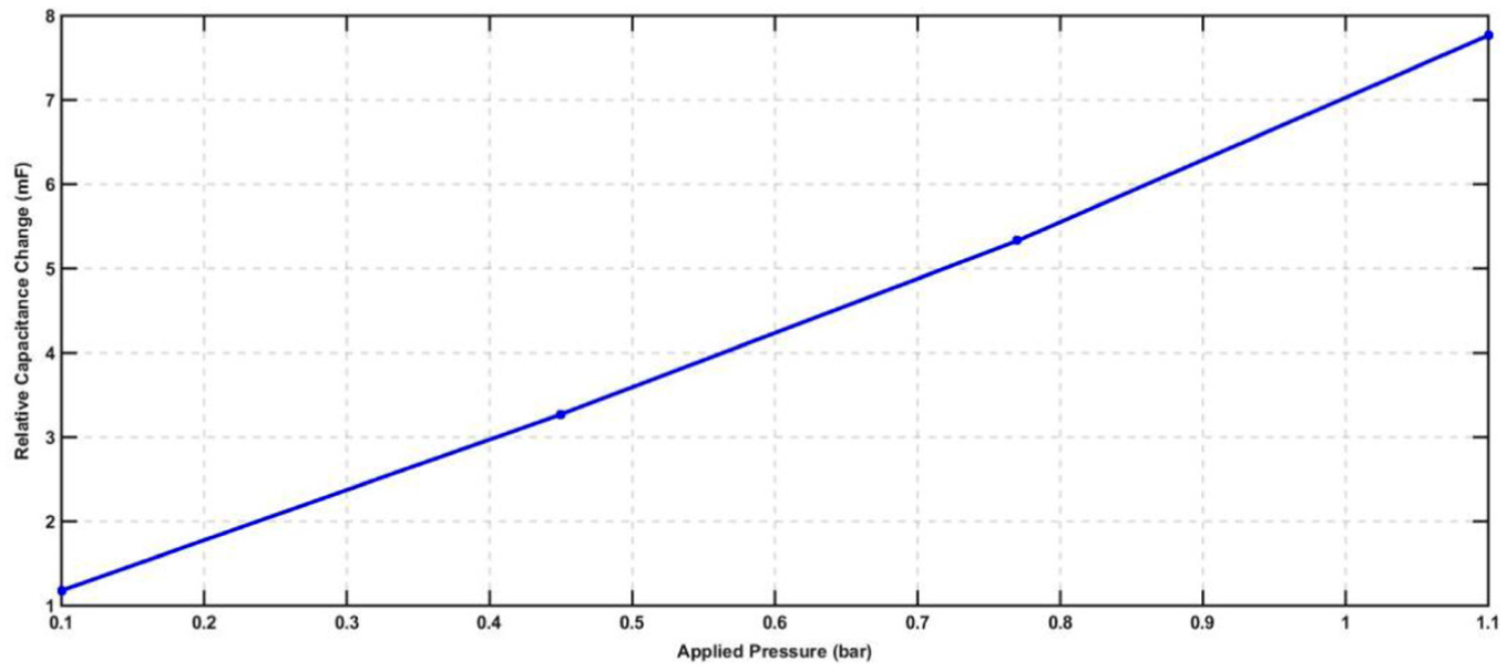
Relative capacitance variation with respect to zero pressure condition.
In Figure 8, resonant frequency points are under discussion. At resonance, the output is reduced due to the resistive reflected impedance, which tries to lower the quality factor of the primary. To enhance the performance of the output, the coupling must be compensated. We get inductive reflected impedance at frequencies lower than the exact resonance point, which produces a peak at the output and we get capacitive reflected impedance at frequencies higher than exact resonance point, which results in another peak in the output. Performance is investigated for P = (100–1140) mbar, r = 180 µm, E = 170 × 109 N/m2, ν = 0.28, L0 = 4.35 mH, Ls = 4.35 mH, R0 = 4 kΩ and Rs = 4 kΩ. Figure 8 is a result of simulating equations (13) and (14). Resonant frequency points at two angular frequencies for proposed design are 4.55 × 10⁷ rad/s and 5.53 × 10⁷ rad/s. The data belong to the observer side.
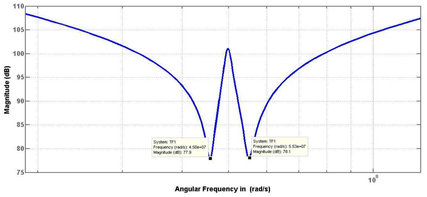
Resonant frequency points at two angular frequencies for proposed design at 4.55 × 10⁷ rad/s and 5.53 × 10⁷ rad/s.
As a solution to above, if we make capacitance at observer unit variable (wireless control) and vary it to such a degree that even under pressure resonant frequency doesn’t shift, then we can sense applied pressure in terms of capacitance for the desired range of (100–1140) mbar. In Figure 9, capacitance variation at primary observer unit to sense the applied pressure range is investigated. Figure 9 is a result of simulating equation (2) with applied pressure against obtained capacitance. Performance is investigated for P = (100–1140) mbar, r = 180 µm, a = 250 µm, E = 170 × 109 N/m2 and ν = 0.28. It can be observed that minimum capacitance at 100 mbar is 0.174 pF and maximum obtained capacitance is 0.196 pF at 1140 mbar. The data belong to the observer side. The capacitance variation at primary observer unit to sense the applied pressure range is compared with work done in previous works.14,21 Here, since the pressure range is low, the simulated graph shows a linear response throughout. In Jindal and colleagues14,21, pressure range in normal mode is (0–0.2) MPa and hence we received a non-linear response. Moreover, response in Jindal and colleagues14,21 is extended to touch mode of the sensor for pressure range of (0.2–2) MPa. Highly non-linear response can be observed since the pressure range is very high.
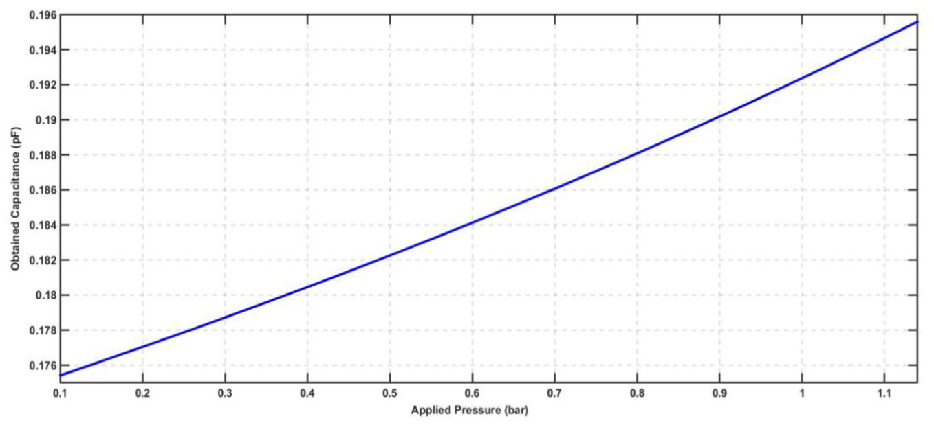
Final capacitance variation at primary observer unit to sense the applied pressure range.
Figure 10 shows the variation of the capacitive sensitivity with respect to the variation in the radius of the circular diaphragm. Figure 10 is a result of simulating equation (23) with radius of diaphragm against capacitive sensitivity of proposed sensor. Performance is investigated for d = 10 µm, h = 5 µm, r = 180 µm, a = 250 µm, E = 170 × 109 N/m2 and ν = 0.28. It illustrates that with the increase in the radius of diaphragm at a fixed thickness and uniform pressure, the deflection on the circular diaphragm increases. Validating a design consideration from Figure 10, we can justify the choice of having radius for our sensor design to be 250 µm. At this geometry of diaphragm radius at a fixed thickness of 5 µm, the variation in the above plot is almost constant. The data belong to the sensor side. The variation of the capacitive sensitivity with respect to the variation in the radius of the circular diaphragm is compared with the work done in Jindal et al. 14 The response curve and inference in both the cases are same, but the magnitude of capacitive sensitivity is different because value of gap depth chosen is different.
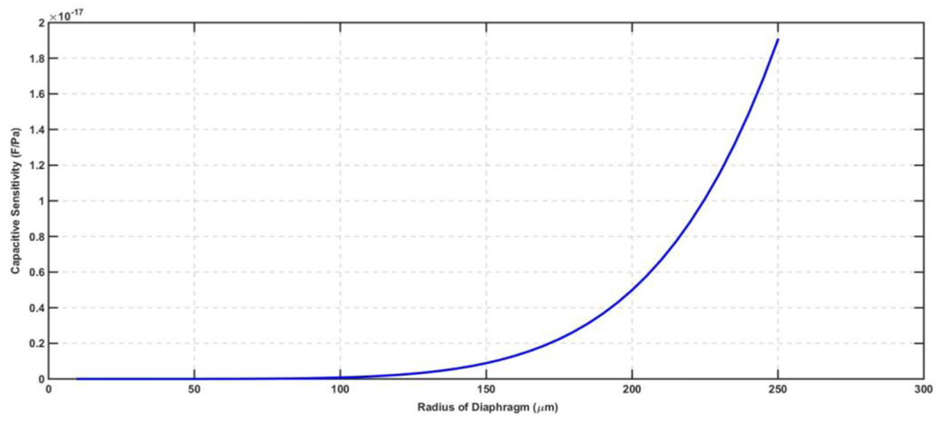
Variation of capacitive sensitivity with the variation in the diaphragm radius at a fixed thickness and pressure.
In Figure 11, variation of the mechanical sensitivity analogous to the variation in the diaphragm thickness is investigated. Figure 11 is a result of simulating equation (25) with thickness of diaphragm with mechanical sensitivity. Performance is investigated for h = 5 µm, r = 180 µm, E = 170 × 109 N/m2 and ν = 0.28. It can be concluded from Figure 11 that with the increase in diaphragm thickness, the mechanical sensitivity decreases. This is because with the increase in diaphragm thickness, deflection decreases. The data belong to the sensor side. Another claim to validation of chosen geometry is the choice of diaphragm thickness. Beyond 5 µm if the thickness is further increased, the mechanical sensitivity drops by a considerable amount which is inadmissible. The variation of mechanical sensitivity analogous to the variation in the diaphragm thickness is compared with the work done in Jindal et al. 14 The response curve and inference in both the cases are same, but the magnitude of mechanical sensitivity is different because the value of radius of diaphragm chosen is different.
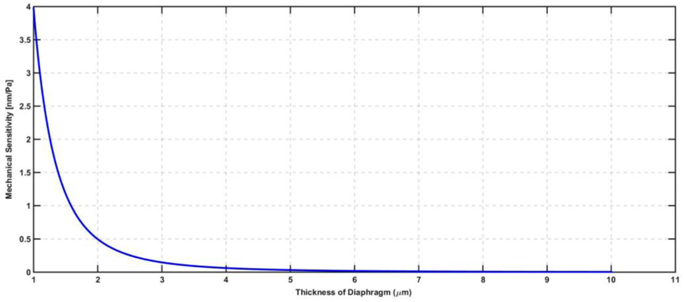
Variation of mechanical sensitivity with the variation in the diaphragm thickness at a fixed radius and pressure.
Conclusion and future work
This research has explored a unique methodology for LC tank circuit–based wireless MEMS capacitive pressure sensor which can measure applied pressure by changing the capacitance and keeping frequency shift constant. Sections ‘Introduction’ and ‘Transduction mechanism of capacitive pressure sensor’ introduced the concept of wireless sensing using LC tank circuit with proper insight to literature review. Since capacitive pressure sensor is a vital member of the design, the transduction mechanism for this sensor has been elucidated in ample capacity. Next, two sections delineate in depth the step-by-step theoretical evaluation of crucial parameters. Section ‘Preliminary investigations by simulations and interpretations’ delved into depth graphically analysing the methodology for the refined model and comparing the results with intuitive predictions. It was observed that the resulting capacitance variation on keeping frequency shift constant can also be used for passive measurement of applied pressure. The performance in sensitivity was also observed to be as per fondness and validity of avionic applications. The maximum sensitivity was observed to be 1.746e−17 F/Pa. The comparison between the simulation result and theoretical response obtained revealed the effectiveness of the model in predicting the sensor response. The presented methodology-based wireless Si MEMS is the first building block of a platform for autonomous industrial sensors and has all the essential characteristics necessary for integration into harsh industrial environments. The compact, single-substrate design leaves plenty of room for replacement of Si with SiC, operation of sensor in touch mode, as a future work for even better performance of target application.
Footnotes
Declaration of conflicting interests
The author(s) declared no potential conflicts of interest with respect to the research, authorship and/or publication of this article.
Funding
The author(s) received no financial support for the research, authorship and/or publication of this article.