
Abstract
In this paper, a hybrid fault tolerant control system is proposed for air–fuel ratio control of internal combustion gasoline engines based on Kalman filters and triple modular redundancy. Hybrid fault tolerant control system possesses properties of both active fault tolerant control system and passive fault tolerant control system. As part of active fault tolerant control system, fault detection and isolation unit is designed using Kalman filters to provide estimated values of the sensors to the engine controller in case of faults in the sensors. As part of passive fault tolerant control system, a dedicated proportional–integral feedback controller is incorporated to maintain air–fuel ratio by adjusting the throttle actuator in the fuel supply line in faulty and noisy conditions for robustness to faults and sensors’ noise. Redundancy is proposed in the sensors and actuators as a simultaneous failure of more than one sensor, and failure of the single actuator will cause the engine shutdown. Advanced redundancy protocol triple modular redundancy is proposed for the sensors and dual redundancy is proposed for actuators. Simulation results in the MATLAB Simulink environment show that the proposed system remains stable during faults in the sensors and actuators. It also maintains air–fuel ratio without any degradation in the faulty conditions and is robust to noise. Finally, the probabilistic reliability analysis of the proposed model is carried out. The study shows that the proposed hybrid fault tolerant control system with redundant components presents a novel and highly reliable solution for the air–fuel ratio control in internal combustion engines to prevent engine shutdown and production loss for greater profits.
Keywords
Introduction
Introduction to fault tolerant control
A fault is defined as the deviation of a plant parameter from its normal operating value. Faults in a system may lead to failure of the complete system to perform its intended function. A fault tolerant control system (FTCS) has the ability to operate under fault conditions and remain stable; however, some performance degradation may occur. Such systems are used in safety and mission critical applications such as airplanes, nuclear facilities and unmanned air vehicles (UAVs) where system failure must be avoided due to the safety of human lives, mission, and environment.1–4
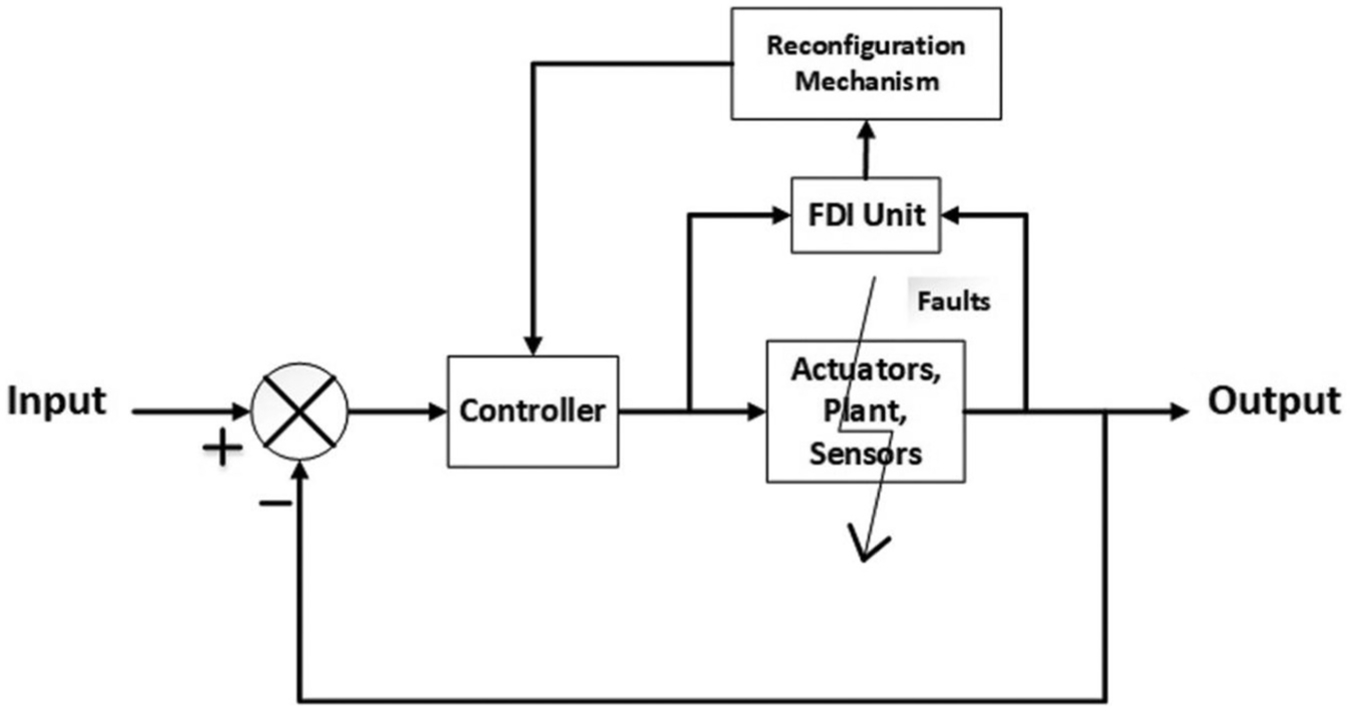
FTCS are classified into two main categories: active and passive due to differences in their architectures and properties.1,5,6 In the active fault tolerant control system (AFTCS), fault detection and isolation (FDI) performs core function to detect, locate, and isolate the faulty components in the system online. In FDI, the algorithm works on observer principle such that it generates a residual by comparing the plant parameter with a normal predefined value. If the residual comes out to be within bounds, no fault is declared by the system. A fault is declared by the FDI unit if the residual is calculated to be out of the defined limit. It then performs the controller reconfiguration for adaptability to new operating conditions. Performance degradation may occur due to faulty components, but the stability of the system remains assured. The structure of AFTCS is shown in Figure 1.7–10
Structure of AFTCS.
To explain observer design for the AFTCS process as described in the studies by Wang et al. 7 and Nise, 11 the system can be represented in state space as follows


where “x,”“u,” and “y” denote the states, inputs, and outputs of the system and A, B, C, and D denote system matrices.
Let


where


where


If the residual “
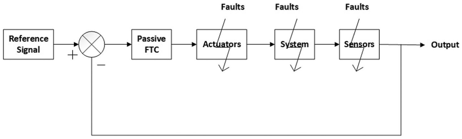
In the passive fault tolerant control system (PFTCS), no FDI is implemented and all faults are preconfigured in the design stage. The controller works in offline mode and has a faster response than AFTCS due to fewer computations. However, it can only tolerate those faults that are already considered in the design stage. The structure of PFTCS is shown in Figure 2.13,14
Structure of PFTCS.
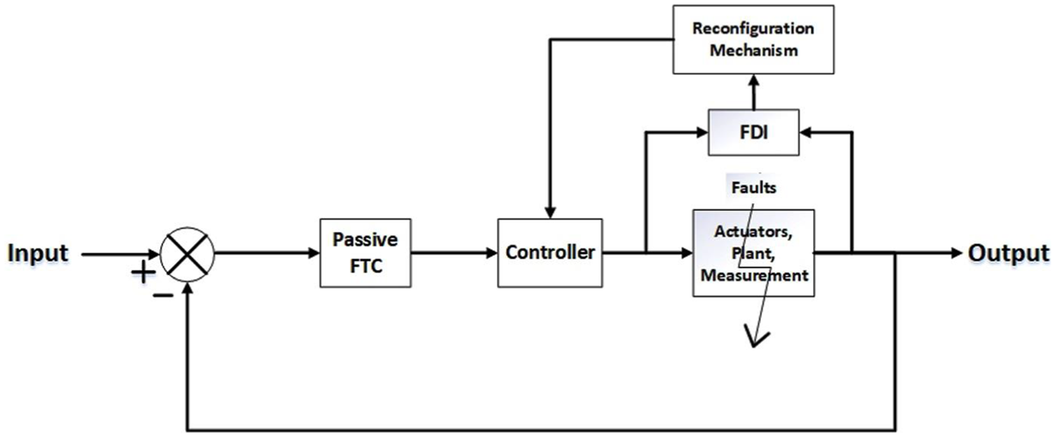
Hybrid of both these techniques makes hybrid fault tolerant control system (HFTCS) have salient properties of each system. In the HFTCS, the system can respond fast in safety applications for faults utilizing the PFTCS characteristic and then optimize later utilizing the AFTCS property. The type of system proposed in this paper is quick and optimal. The structure of HFTCS is shown in Figure 3.15–18
Structure of HFTCS.
Feedback control is a famous robust control strategy which is widely used in the process industry to achieve the desired closed loop response. 19 A robust controller can be made with high gain feedback that makes it robust to other parameter variations due to this high gain. Sliding mode control is another popular approach for the design of a robust control system.20–22
Redundancy is an important aspect to increase the fault tolerance capability of a system and can be categorized into two types: direct and analytical. In the direct redundancy, a simple form is a dual redundant assembly in which two components are installed in parallel performing the same function. When a fault arises in the primary component, the secondary component comes into operation isolating the faulty one and preventing process interruption.
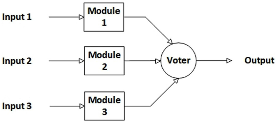
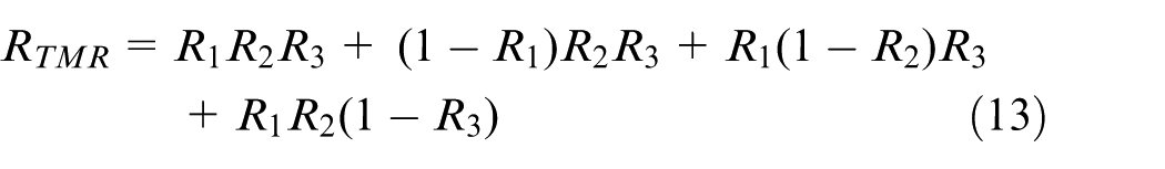
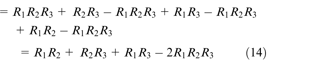
Triple modular redundancy (TMR) is an advanced hardware redundancy protocol for achieving high reliability, as shown in Figure 4. In TMR, three parallel channels produce output from similar inputs independently and a voter circuit performs voting among these to generate a single output. If a channel becomes faulty, it is detected by the voter and the operator is alarmed by annunciations to replace the faulty module meanwhile the voting is performed from the other two healthy channels and single point of failure is avoided.23,24
Architecture of triple modular redundancy (TMR).
Let
If


TMR has been widely used for various applications for reliability enhancement. In the work by Krstic et al., 25 it is used for very-large-scale integration (VLSI) voter system to determine mid or median value among four sensors. Şinca and Szász 26 proposed digital systems at a nanoelectronic level for complementary metal-oxide-semiconductor (CMOS) circuit and simulation results have been presented. Hudson et al. 27 implemented operating systems. However, limitation of TMR is that if system failure occurs in case of simultaneous faults in two channels, then the voter will not be able to produce output from a single channel. The reliability is significantly increased by replacing the faulty module. 23
In the analytical redundancy technique, a software model of the system is designed to create virtual values of the plant components that are used in case of failure of actual components. Thus, analytical redundancy saves hardware cost of the component and physical space with a weight which are highly desirable features for applications such as airplanes and UAVs. Single point of failure is a situation in which the full system failure can occur by a single fault and, therefore, must be avoided in the design of reliable control systems.23,28
AFTCS has been implemented using various techniques. In the work by Yuan et al., 29 KF has been used for fault detection and location (FDL) for the coexistence of sensor and actuator faults. In the study by Li and Tong, 30 fuzzy logic has been used in for estimation of a nonlinear function and adaptive control is implemented for the actuator faults. In Tang et al., 31 neural networks have been used in using average dwell method. In Carbot-Rojas et al., 32 a nonlinear adaptive observer has been implemented using virtual sensor values in the FDI to estimate the flow rates for actuator fault in a double pipe heat exchanger. In Patel and Shah, 33 PFTCS has been reported using fuzzy logic and proportional–integral (PI) controller for a single tank level system under system faults and process disturbances. In Murtaza et al., 34 super twisting control-based unified FDI and FTC scheme is reported for air path of diesel engines. In Pourbabaee et al., 35 HFTCS is implemented using multiple KFs in the FDI design for gas turbine engines.
Our contribution is the design of novel HFTCS for reliable operation of air–fuel ratio (AFR) control of the internal combustion (IC) gasoline engine containing both analytical and advanced hardware redundancies for greater overall reliability of the process machine to prevent production loss. Proposed HFTCS has AFTCS based on KF and PFTCS based on high gain proportional feedback controller for AFR control. The proposed system is able to make up the AFR degradation by AFR controller through a fuel throttle actuator. Furthermore, advanced hardware redundancy protocol TMR is proposed for sensors, and dual redundancy is proposed for actuators to avoid engine shutdown due to simultaneous failure of more than one sensor and a single point of failure by actuators. Finally, a brief reliability analysis is carried out to compare the reliability of a new model with the existing MATLAB model to prove its enhanced reliability.
Such type of FTC for AFR control is not found in literature so far up to our best knowledge. The proposed system is quite significant for further research and implementation in modern IC gasoline engines to achieve more reliability and greater profits in production plants. The system is able to tolerate simultaneous faults in sensors and actuators. The proposed technique is very much effective in terms of robustness to faults and noise in the sensor measurements as compared to other existing techniques mentioned earlier. The assumption of the study is the operation of the engine in the linear range of the nonlinear Manifold Absolute Pressure (MAP) sensor. The advantage of this assumption enables the implementation of linear control theory concepts in the model with less complexity. Limitations of the study are the consideration of full failure type faults for sensors and actuators without considering the partial faults of additive type. Another limitation is that the simultaneous failure of any two sensors of a single TMR assembly or simultaneous failure of both actuators in the redundant assembly will cause engine shutdown.
The contents of the paper are organized as follows: section “Research methodology” explains the research methodology with assumptions and limitations. Results and discussion are presented in section “Results and discussions.” Conclusion with the future research direction is presented in the last section.
Overview of Kalman filter and application in FDI
Kalman filter (KF) is a recursive algorithm to provide an estimate of the state of the system in terms of time update and measurement update steps minimizing the mean square error and considering past, present and even future states of the system. In time update, prediction of the state of the system is performed along with uncertainties. After prediction, states are updated with measurements by giving more weight to estimates with greater certainty. This step is called a measurement update. This is a recursive process.
Mathematical functioning of KF is described in Welch and Bishop 36 as follows. Consider the linear stochastic difference equation for a discrete-time system


where x∈ℜ n and z∈ℜ m are state and measurements, respectively. wk and vk represent process and measurement noises, respectively. It is assumed that these are independent, white, have zero mean and normally distributed with distributions as follows


Where “Q” and “R” are process and measurement covariance matrices.
Let


Priori estimate error covariance would be as follows

Posteriori estimate error covariance would be as follows

The estimated posterior state would then be calculated from prior and the difference between measured and prior estimates state, as follows

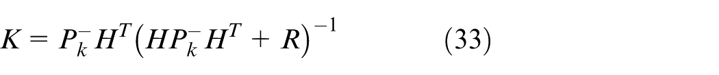
Where K is the Kalman gain and computed as follows
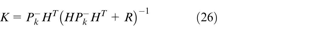
When R approaches zero, we have
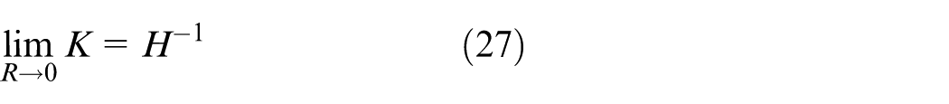
When


Discrete KF time update or prediction equations are as follows


Discrete KF measurement update equations are as follows


The greatest advantage of KF is that it can provide a quality estimate (with variance) and has a low level of complexity. Its major disadvantage is that it works well for Gaussian and linear models only. For non-linear Gaussian models, extended KF (EKF) is used. For nonlinear, non-Gaussian models particle filters (PFs) are used.
Extensive research is being carried out for FDI development with KFs to achieve analytical redundancy. Chetouani 37 use EKF for FDI in nonlinear dynamical processes. FDI detects an abnormality in the process with the time of occurrence according to the noise in the process and uses multiple EKFs for non-stationary nonlinear dynamic processes is also elaborated thus covering all types of fault dynamics models. In Trinh and Chafouk, 38 FDI for faults in the current sensor in a doubly fed induction generator in wind turbines is described. Generalized and dedicated observer schemes are presented for multiple and simultaneous sensor faults. In Van Eykeren et al., 39 an adaptive EFK is proposed that uses kinematic relations of aircraft to introduce analytical redundancy and isolate faulty sensors using estimated covariance. In Pourbabaee et al., 35 multiple hybrid KFs (MHKFs) are proposed for FDI based on piecewise linear models to cover the entire operational range using a Bayesian approach. Simulation of the proposed approach is carried out for a gas turbine engine model. In Yuan et al., 29 FDL is proposed for nonlinear aero-engine utilizing a matrix of hybrid KFs for the coexistence of faults and health degradation. In Bardawily et al., 40 EKF is used as an extended multiple model adaptive estimator (EMMA) for FDI design and implemented on the industrial boiler. In Chen et al., 41 unscented KF (UKF) is proposed for FDI and state estimation in the presence of unreliable measurements and correlated noise. However, the use of KF for AFR control of IC engines is not found in the literature so far motivating us to conduct this research study.
Air fuel ratio control of the IC engine
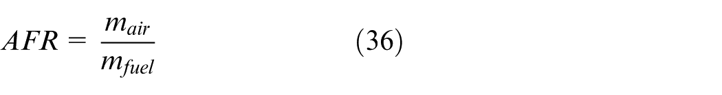
IC engines are widely used equipment in the process applications as the prime mover. Chemical energy of the fuel is converted to mechanical rotational energy by these engines and further applied to drive the compressors and alternators. These are categorized as spark ignition (SI) and compression ignition (CI) engines. In the SI engines, spark plugs are used in the combustion process, whereas in CI engines spark plugs are not used and combustion is performed only by compression. We have considered SI IC engines in our study. Proper mixing of air and fuel in the combustion process in a definite ratio is termed as an AFR and is very important for increased engine efficiency, fuel energy savings and low hazardous emissions for environmental protection. 42 AFR is expressed mathematically as follows
The chemical equation for the combustion process of gasoline fuel is given as

AFR according to this equation is termed as the stoichiometric ratio and its value is 14.6:1 for the gasoline fuel. This mixture is called a stoichio mixture. AFR in the combustion process of gasoline can go from 6:1 to 20:1. Mixture with greater fuel than this ratio is termed as a rich mixture and with fuel lesser than this ratio is termed as a lean mixture. For example, AFR of 16.5:1 is lean and AFR of 13.7:1 is rich for the gasoline. Both rich and lean mixtures are not considered optimum for combustion. The value of AFR is different for different types of fuels. For example, its value is 6.47:1 for methanol, 9:1 for ethanol, and 34.3:1 for hydrogen. 43 In this study, we have considered gasoline engines and designed AFR controller for 14.6. The main purpose of the AFR controller in IC engines is to maintain this ratio for optimum combustion benefits. It also offers benefits of reduced hazardous emissions and fuel energy savings with increased efficiency of the gasoline engine.
The air–fuel mixing system of a gasoline SI IC engine is shown in Figure 5.44,45 Air is passed through the filters to remove dust particles and its flow is regulated by an air throttle regulator. Fuel is also first filtered and pumped to the engine manifold for air–fuel mixing. We have introduced a fuel throttle actuator to control the fuel flow after which it is mixed with air and the mixture is then passed to the engine cylinders for the combustion process.
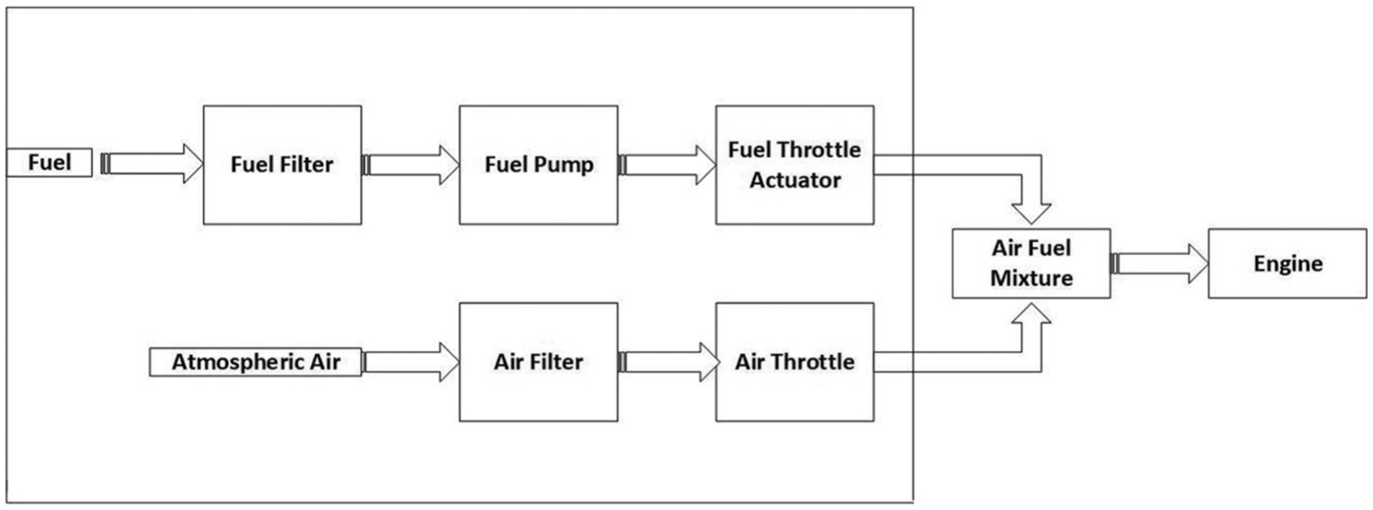
Air fuel system of SI IC gasoline engine.
The AFR controller is implemented in the engine control unit (ECU) to maintain AFR at 14.6 for the gasoline engine. AFR controller performs its function utilizing sensors and actuators. Faults in these sensors and actuators will create uneven combustion and will ultimately cause engine shutdown. The shutdown of the engine will further interrupt the process and lead to production loss thus reducing profits. Moreover, increased downtime of the engine in repairing and troubleshooting of faults will also increase production loss. Therefore, the idea of FTC is utilized to prevent the shutdown of the engine to maintain its stable functioning even in faulty conditions within safe limits to prevent production loss and increase production profits.
Various techniques and methodologies have been used for AFR control of SI IC engines. In Carbot-Rojas et al., 46 a survey on different topics of IC gas engines has been presented which includes modeling, use of biofuels, simulation, and implementation of control laws. In the study by Pace and Zhu 47 sliding mode control (SMC) based multi-input-multi-output (MIMO) controller is designed for AFR control and compared with the baseline multi-loop proportional–integral–derivative (PID) controller to demonstrate its better performance. In the work by Lauber et al., 48 AFR control algorithm is formulated using nonlinear Takagi–Sugeno’s model. In Anjum et al.’s, 49 study, a robust smooth sliding mode control technique is utilized for AFR control that has less chattering effect. In the work by Wu and Tafreshi, 50 fuzzy sliding mode strategy for lean burn, SI engines have been presented that is model-free and does not need any characteristic of the system. Li et al. 51 use a PI like fuzzy logic-based control law for AFR control that is highly robust and capable of self-tuning. In the work by Gutiérrez León et al., 52 an adaptive observer model using mass air flow (MAF) is implemented to provide analytical redundancy for this sensor fault. In García-Morales et al.’s 53 study E-10 hydrogen fuel is used for AFR control implementation in the SI IC engines. In the work by Cervantes-Bobadilla et al., 54 neural network in combination with model predictive control (MPC) and PID control for on-demand production of hydrogen gas is reported for increased combustion efficiency of SI IC gas engines.
MathWorks, 55 presents a fault-tolerant fuel control system for an IC engine in which four sensors and air throttle is used to maintain AFR at 14.6. This model is studied in this paper for further research work. Analytical redundancy is implemented in the model for sensor faults that provide an estimated value of the faulty signal from lookup tables. Four sensors play a major role in the AFR control system and are described as follows:
Throttle sensor: It provides air throttle position to the controller.
Speed sensor. It provides speed signal feedback to the controller.
EGO sensor: It shows the number of oxygen contents in the exhaust gas of the engine and is used in a feedback loop to regulate fuel supply. Greater EGO value causes an increase in fuel supply and lesser EGO value cause a decrease in fuel supply.
MAP sensor. It provides an absolute pressure of suction air present in the air-manifold to the controller. The MAP sensor is nonlinear over the entire range of the throttle actuator. However, it is linear in 10–20 degree rotation of throttle.
In this model, the control law is designed such that fault in any one sensor at a time will not cause engine shutdown due to analytical redundancy. However, in case of a fault in more than one sensor at a time, engine shutdown is triggered. Moreover, fuel throttle actuator is incorporated in our revised model of this study to implement AFR PI controller. The overall aim of the study is to make a highly reliable AFR control system for SI IC gasoline engine using advanced analytical and hardware redundancies with proper FTC architecture which is robust to faults and noise.
Research methodology
HFTCS is implemented on the available model of the IC gasoline engine in Simulink for further study. Preliminary knowledge and working of the model are explained in MathWorks. 55 As explained earlier, HFTCS is a combination of both AFTCS and PFTCS. AFTCS is implemented by designing the FDI unit using KF-based observers. PFTCS is implemented by designing a high gain feedback controller that makes it robust to parameter variations during faults and noise.
The speed of the engine is set to 300 r/min for this study. Therefore, in case of a fault in the speed sensor, a value of 300 is passed to the controller by the FDI unit. In case of a fault in the throttle and MAP sensors, an estimated value is produced by the FDI unit based on KF observations and is fed to the controller.
For obtaining KF parameters in the model for throttle and MAP sensors, linear control design techniques in the MATLAB as explained in MathWorks56,57 are used to obtain transfer functions and state space model parameters. These parameters in terms of system matrices A, B, and C are fed to KFs for throttle and MAP sensors. The fault is simulated in this actuator and its effect on the engine is demonstrated by simulation. A fault in the air throttle actuator is also simulated to determine its effect on the AFR.
Faults in the single actuators will cause engine shutdown and are single points of failure. Therefore, the dual redundant assemblies are proposed for these actuators. Since fault in any sensor causes degradation of AFR from 14.6 to 11.7 in the original model, a proportional feedback controller is implemented to maintain AFR at 14.6 in faulty conditions. This controller makes the proposed HFTCS robust to faults in the sensor and serves as PFTCS part of the overall system. Noise is then introduced in the sensor measurements to check the robustness of the proposed HFTCS to noise.
Proposed HFTCS based on KF provides analytical redundancy by providing an estimated value of the sensor, in case of a fault in one sensor at a time. However, faults in any two sensors simultaneously despite analytical redundancy will cause engine shutdown. Therefore, an advanced redundancy protocol TMR is proposed for sensors. Hence, HFTCS with TMR sensors and dual redundant actuators provides an optimum solution for increased reliability of AFR control in IC engines.
The assumption of the study is the operation of the engine in the linear range of the nonlinear MAP sensor. The advantage of this assumption enables the implementation of linear control theory concepts in the model with less complexity. Limitations of the study are that only full failure type faults are considered without considering partial faults in the sensors and actuators. Moreover, the simultaneous failure of two sensors in a single TMR assembly or simultaneous failure of both actuators in redundant fuel actuator assemblies will cause the engine to shutdown.
Results and discussions
Implementation of HFTCS
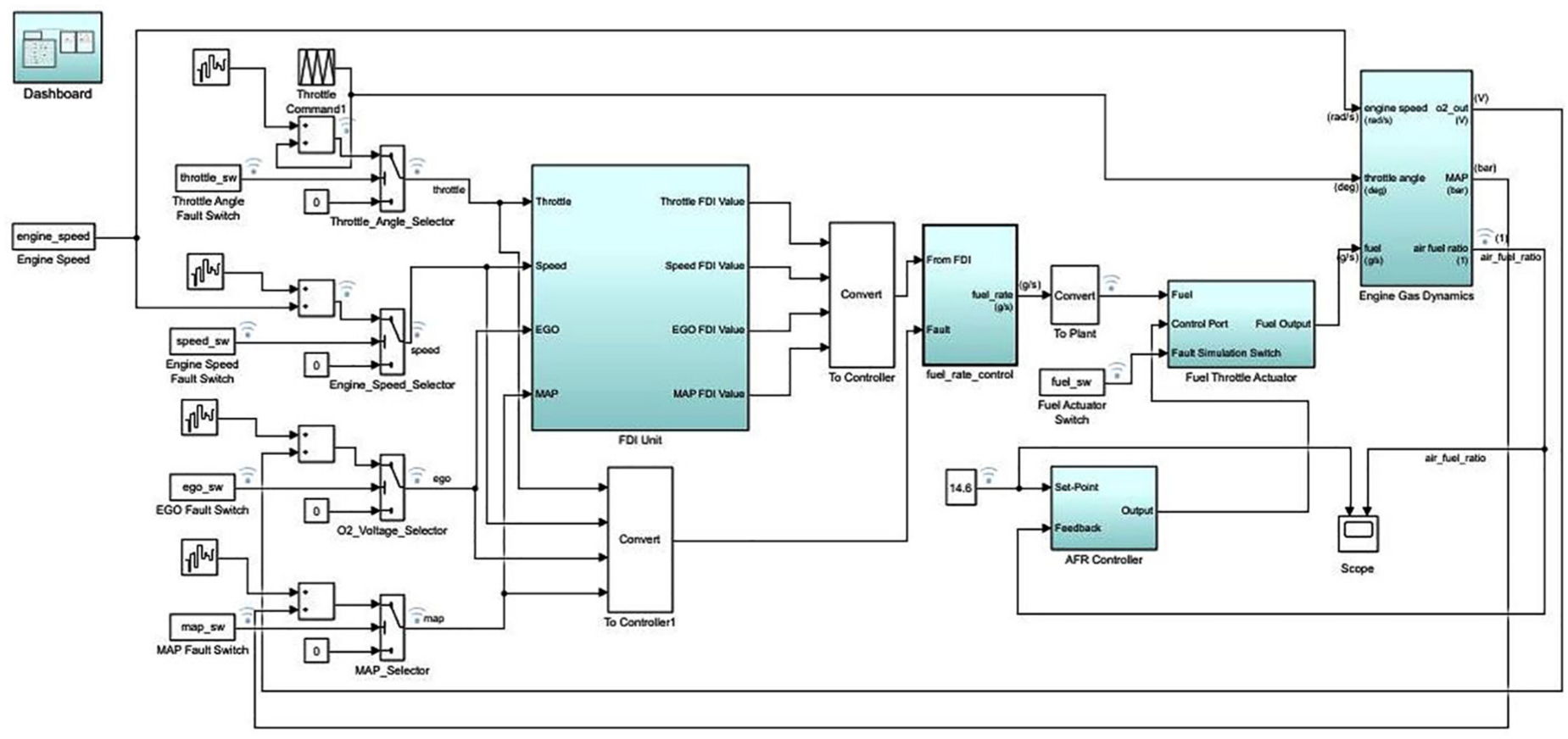
AFTCS part of the proposed model implemented on the IC engine in Simulink is shown in Figure 6. FDI is implemented in the model with KFs for fault detection, isolation, and controller reconfiguration.
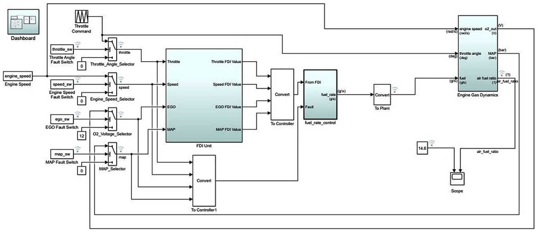
Implementation of AFTCS part in MATLAB.
The working logic of the FDI unit implemented in the study is shown in Figure 7. It monitors the sensor values continuously to detect any fault. A fault is identified if the value of the sensor goes out of the defined limit. Once the fault is detected, the faulty value is replaced by the estimated value obtained from the observer model based on KFs and fed to the ECU. The production of the estimated virtual value of the faulty sensor provides the analytical redundancy in the model.
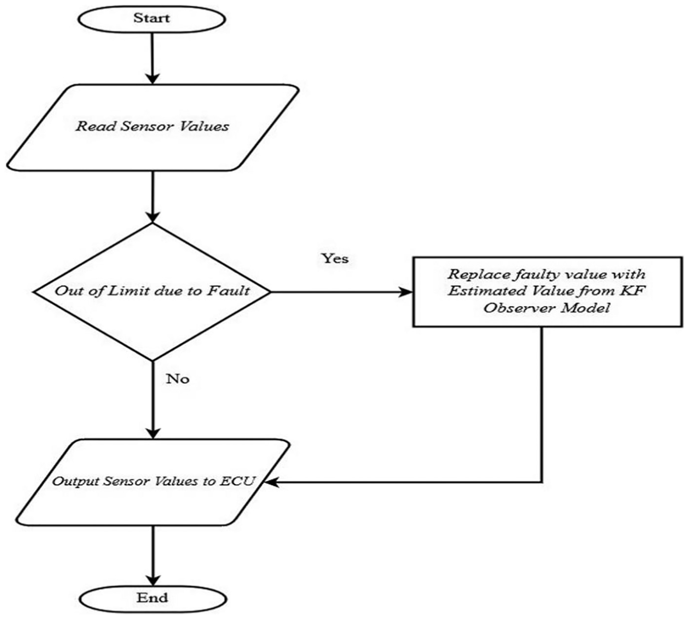
FDI unit architecture of AFTCS.
Two KFs for MAP and throttle sensors are implemented. Since the engine is assumed to run at 300 r/min, this value is fed to the controller in case of a speed sensor fault. Linear system design toolbox is used in Simulink to obtain matrices A, B, C, and D for the MAP and throttle. These values are incorporated in KF blocks in the estimation block and are shown in Table 1.
Parameters for Kalman filters.
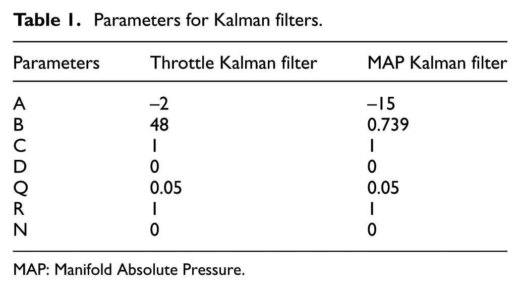
MAP: Manifold Absolute Pressure.
The AFTCS part is simulated with faults in the sensors taking one sensor at a time, and the effects on the AFR are observed at t = 5 s as per model computations and shown in Figure 8.
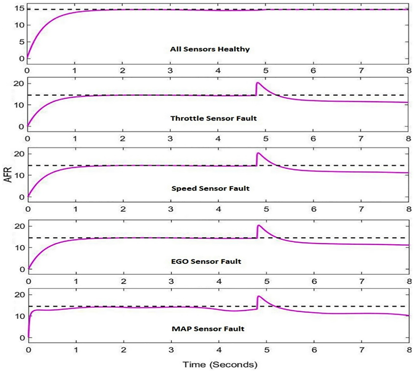
AFTCS performance for single-sensor faults.
Results of Figure 8 show that the AFR gets degraded to 11.7 in the steady state with the fault in any one sensor with the AFTCS part alone. The slightly different transient behavior with the MAP sensor fault is caused by the approximate output value obtained from the KF estimation block and is due to numerical computation of the model; however, it is quite negligible.
Passive part of the proposed control system consists of a high gain PI feedback controller. Overall HFTCS model implemented for the IC gasoline engine is shown in Figure 9.
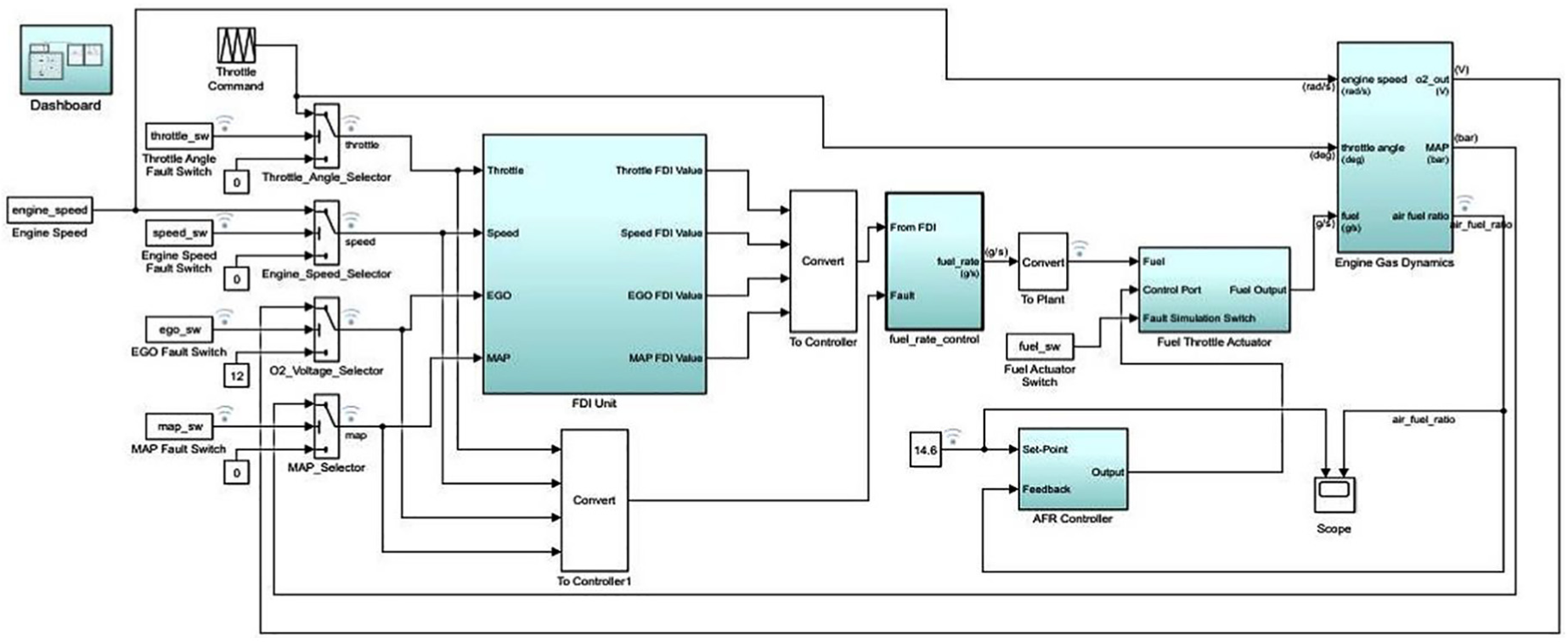
HFTCS implementation with AFR controller.
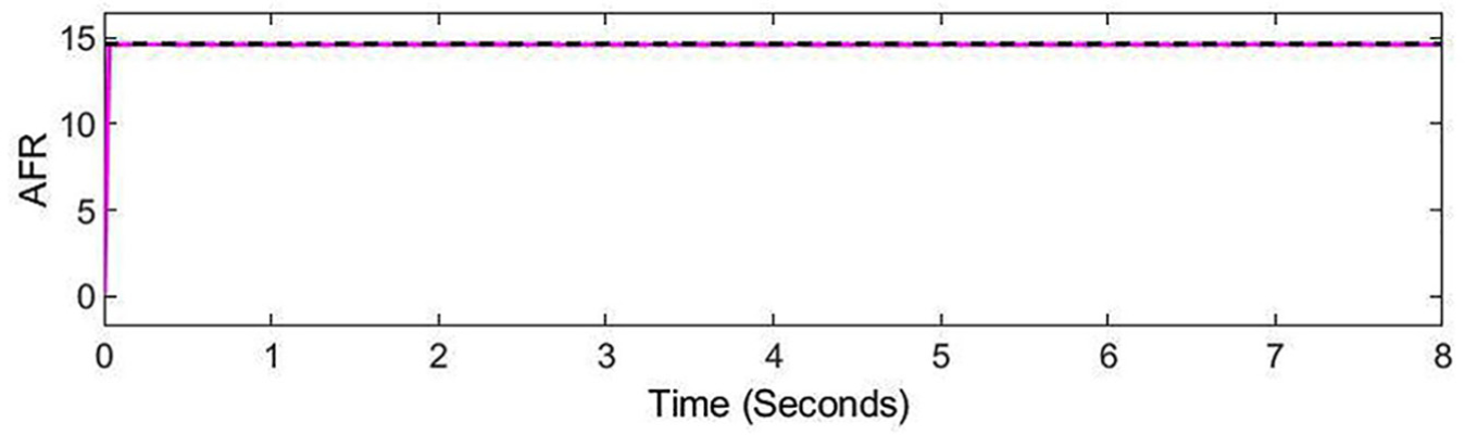
AFR is maintained at 14.6 in faulty conditions making up performance degradation by the AFR controller that is shown in Figure 10. It also makes the system robust to noise and is, therefore, termed as PFTCS part. It is a high gain PI feedback controller that has set point of 14.6 and receives input of AFR. It then issues a command to the fuel actuator incorporated in the fuel supply line for adjustment of fuel to maintain AFR at 14.6.
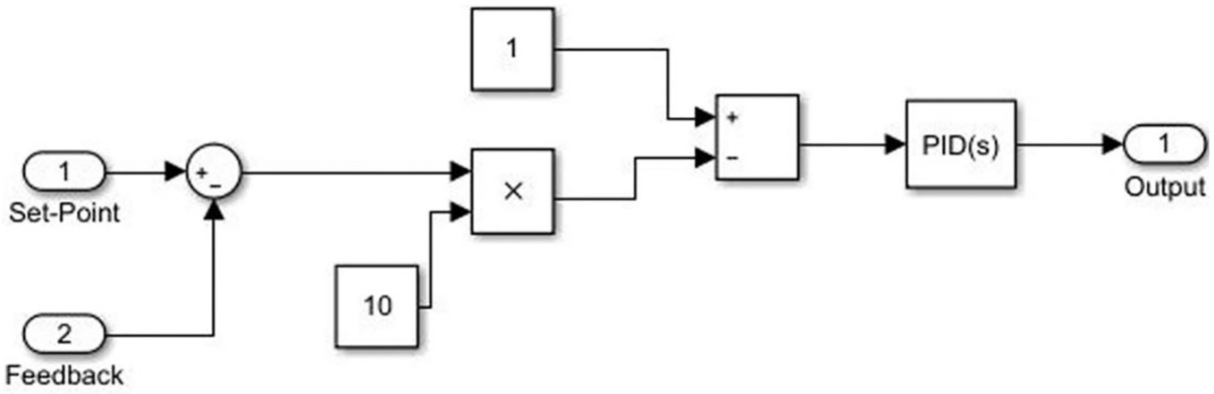
AFR controller architecture.
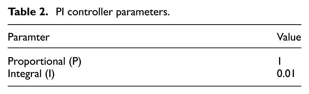
The parameters for the PI control block are shown in Table 2.
PI controller parameters.
The architecture of the fuel actuator is shown in Figure 11. Fuel actuator receives input from the AFR controller output and produces fuel flow output to the engine.
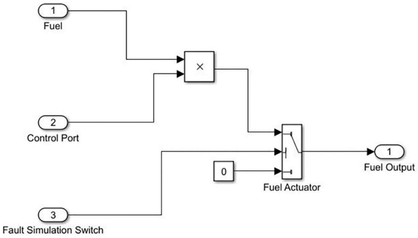
Fuel actuator architecture.
Performance of HFTCS for sensor faults
Overall HFTCS response to AFR by faults in all four sensors is shown in Figure 12. Results show that the system maintains AFR at 14.6 in faulty conditions.
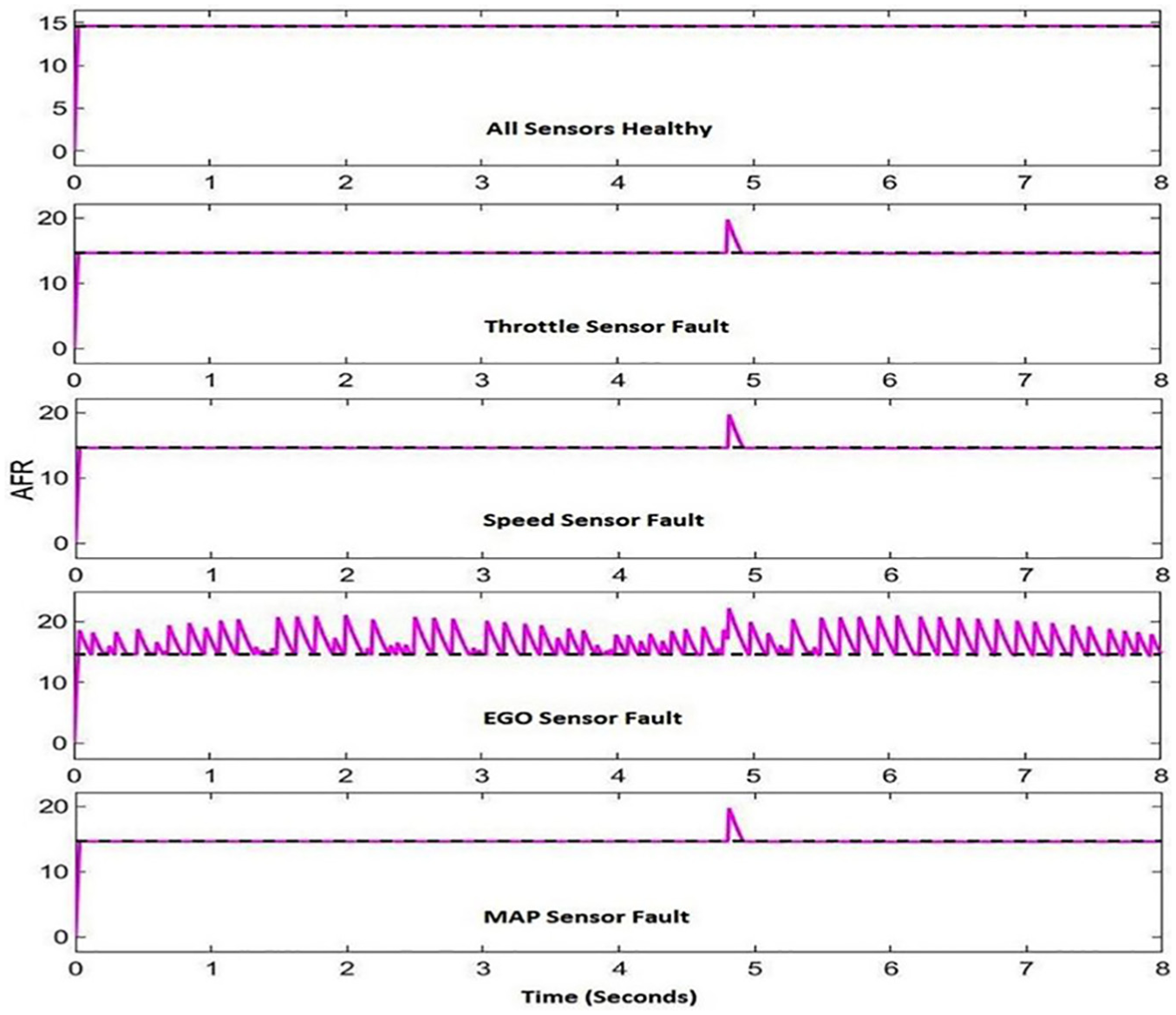
HFTCS performance with single sensor faults.
Results of Figure 15 show that proposed HFTCS is robust to the faults in the sensors maintaining its performance and hence, preventing the degradation of AFR. The spikes in AFR for the EGO sensor fault case are caused due to the estimated value used in place of the EGO sensor by the model.
Stability analysis of AFR
Stability analysis of AFR for the engine in normal and shutdown condition is performed by determining poles and zero locations. For a stable system, poles must lie on the left half plane. 11 Poles and zeros are calculated using system identification toolbox in MATLAB described in MathWorks.58,59
The pole-zero graph for normal AFR for HFTCS shown in Figure 12 is presented in Figure 13.
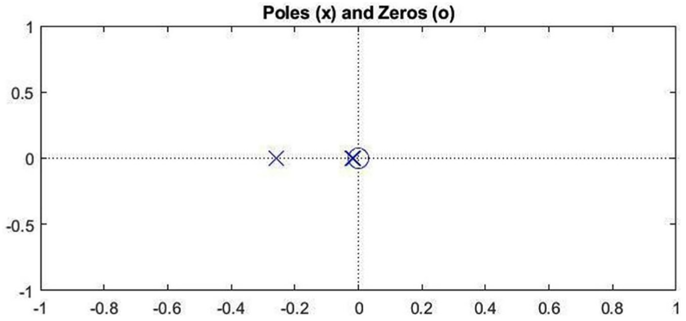
Pole–zero plot for normal AFR.
AFR in the shutdown condition of the engine drastically increases due to cutting off of the fuel supply and is shown in Figure 14.
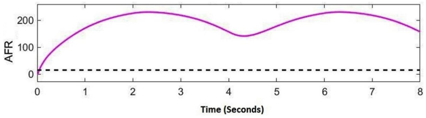
Effect of simultaneous faults in any two sensors on AFR (shutdown condition).
The corresponding pole–zero graph for AFR in the shutdown condition is shown in Figure 15. Poles have significantly moved toward the right, making the overall system somewhat marginally stable. Hence, stability is greatly affected by the shutdown condition of the engine and must be avoided.
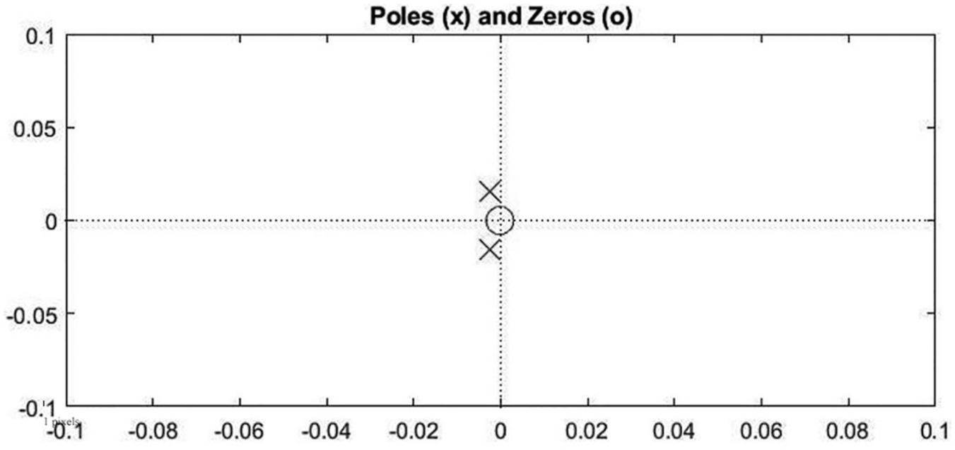
Pole–zero plot for AFR in the shutdown condition.
Performance of HFTCS for actuator faults and redundant actuator assembly
Air and fuel flow in the normal actuator conditions are shown in Figure 16 for comparison with the faulty states. AFR for the AFTCS part is shown here for simplified graphical representation of the fuel and air flow rates. These flow rate limits remain the same for the full HFTCS with some additional glitches due to fuel flow rate adjustments by the AFR controller.
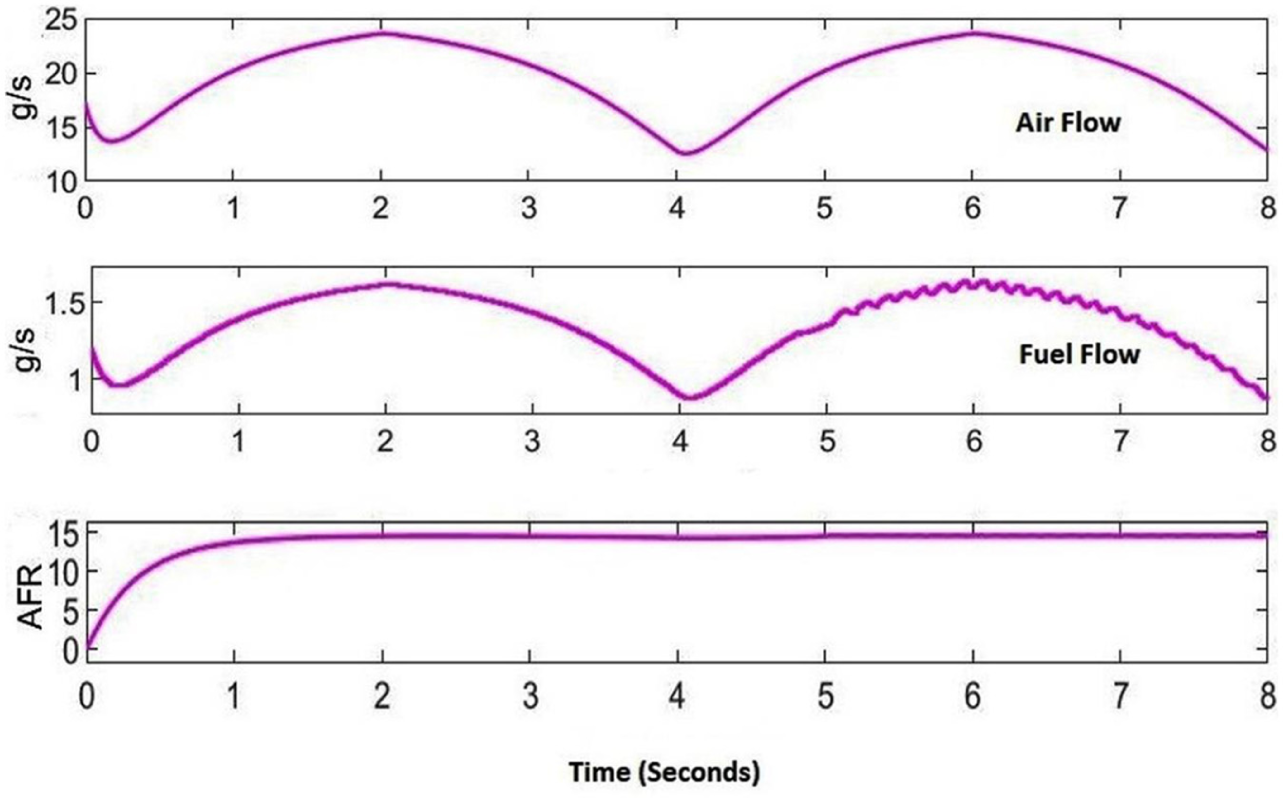
Normal actuators condition.
In Figure 16, the ripples in the fuel flow after 5 s occur due to the switching nature of the EGO sensor. The model is run with the fault simulated in the air throttle actuator to observe its effects on the airflow and AFR. The results are shown in Figure 17. The actuator remains fully closed in the faulty state causing cutting off the air flow and causing AFR to become zero that is in accordance with equation (36). Partial actuator faults are not considered in this study. AFR reduces to zero as a result of air throttle actuator fault causing shutdown of the engine. In case of partial faults, the sensor and actuator values will be varied between their minimum and maximum values range; however, this case is not covered in the current study and has been mentioned in the future works.
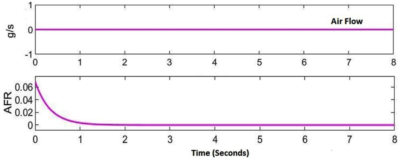
Fault in air actuator and air flow.
The fault is now simulated in the fuel throttle actuator causing cutting off of the fuel to the engine, and AFR increases abruptly out of bounds as shown in Figure 18 causing shutdown of the engine.
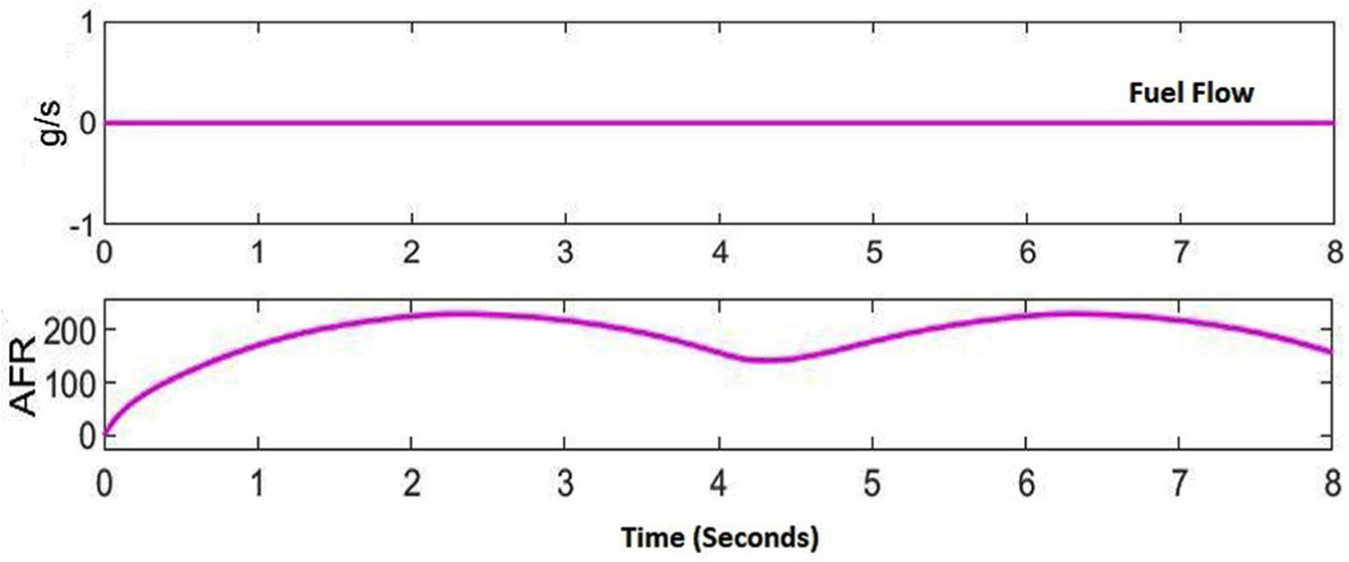
Fault in fuel actuator and fuel flow.
The faults in the single actuator are single points of failure causing complete engine shutdown. Therefore, dual redundancy is proposed for the actuators to avoid the single point of failure. A dual redundant actuator assembly is shown in Figure 19.
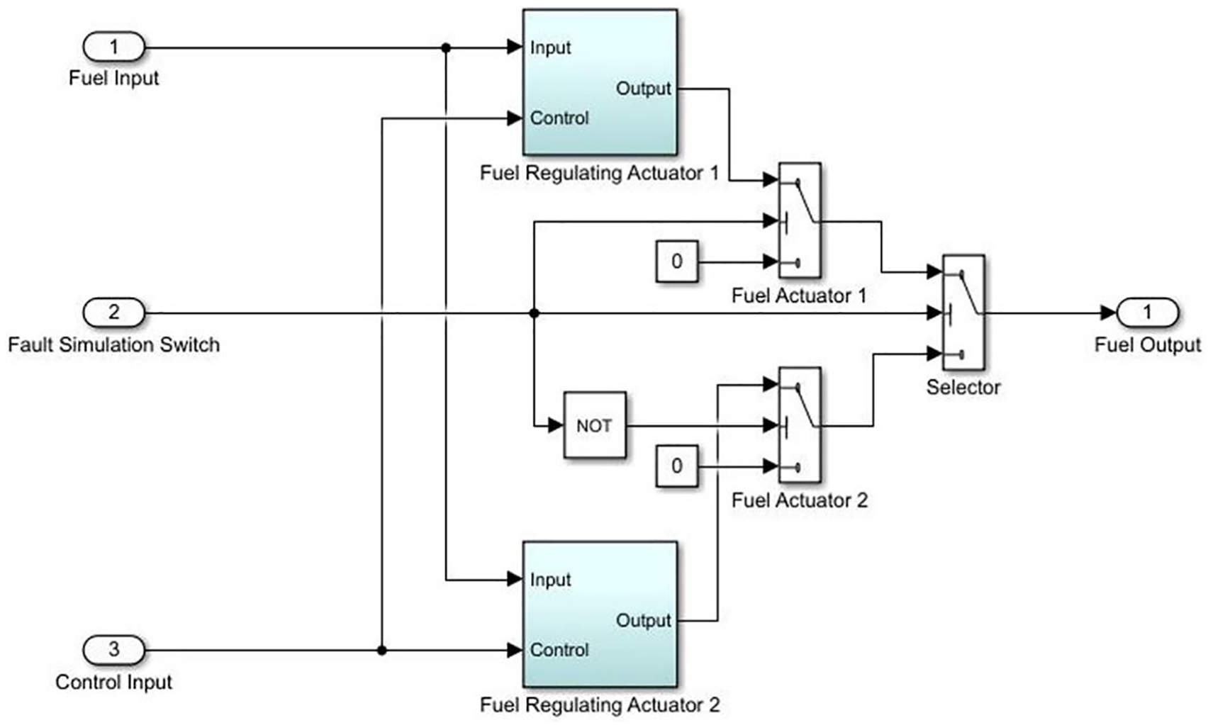
Dual redundant actuator assembly.
In case of a fault in one actuator, another standby comes online thereby preventing the engine shutdown. Now the faults are simulated with dual redundant actuator assemblies in both air and throttle actuators and the effects on air flow, fuel flow, and AFR are obtained same as shown previously in Figure 19 proving the enhanced reliability with hardware redundancy.
Performance of HFTCS with noise
After verifying satisfactory performance in the noise-free operation, the system response is checked by introducing noise in the sensor measurements as shown in Figure 20.
Introducing noise in the HFTCS model.
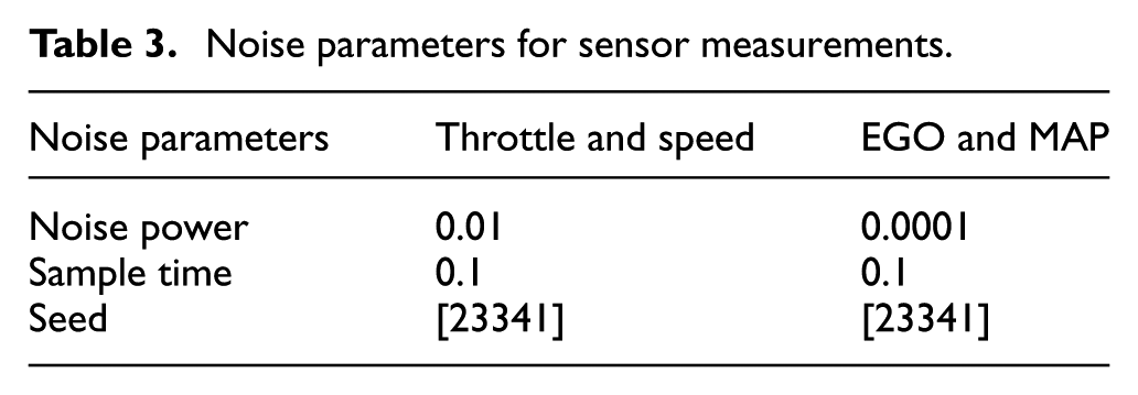
Parameters for noise in all sensors are shown in Table 3. Greater noise is used in throttle and speed sensor measurements due to large values of sensors. Lesser noise is introduced in the EGO and MAP sensors due to the very low range of sensor output.
Noise parameters for sensor measurements.
Effects on the AFR in the normal condition and in faulty conditions are shown in Figure 21. Results show that AFR remains stable with minor glitches and the system remains successful in maintaining AFR.
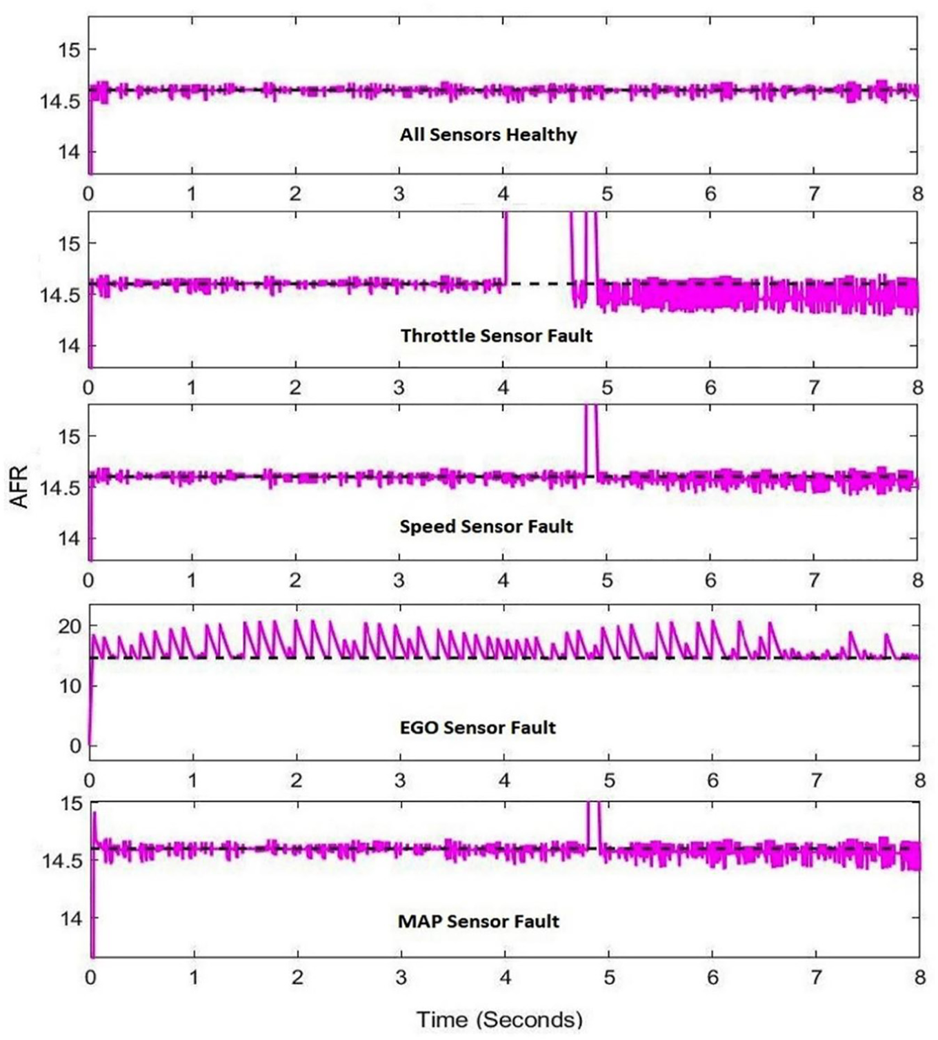
HFTCS performance with faults in noisy conditions.
Results of Figure 21 show that the proposed HFTCS with AFR controller is robust to noise in the normal and faulty conditions and maintains AFR at 14.6 with minor fluctuations.
Implementation of TMR for sensor redundancy
As explained earlier, simultaneous faults in more than one sensor cause engine shutdown. This situation can be prevented by introducing hardware redundancy in the model. An advanced hardware redundancy protocol TMR is implemented for the sensors and is shown in Figure 22.
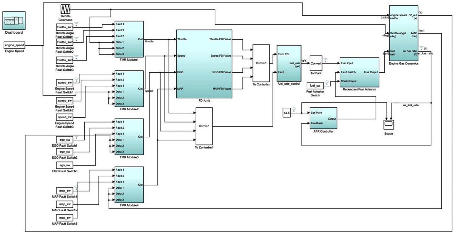
HFTCS model with TMR in sensors.
Effect on AFR in case of simultaneous faults in any two sensors of different TMR assemblies is shown Figure 23.
Effect of sensor redundancy.
The internal architecture of Simulink TMR block implementation is shown in Figure 24. It consists of a control block, a voter port selection block, and voter block.
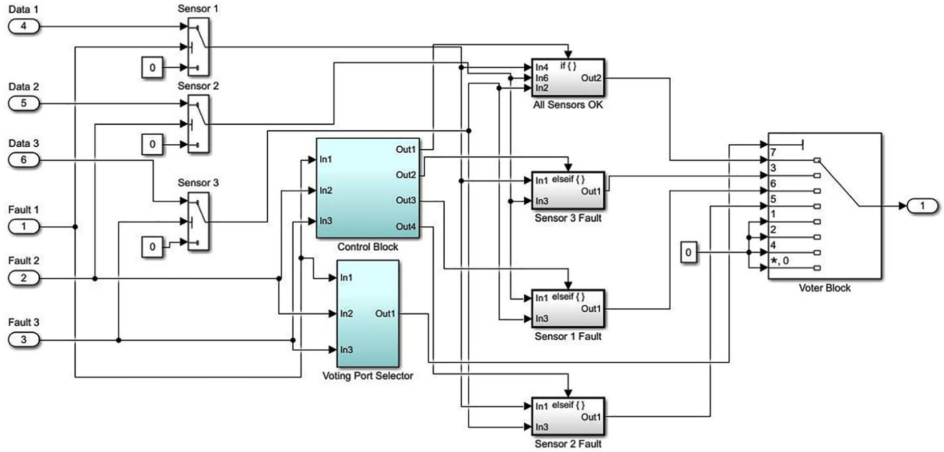
Simulink TMR model architecture.
The architecture of the control block is shown in Figure 25. Four AND gates are implemented to generate an output. Control block generates an output in case of all healthy sensors or two healthy sensors with a fault in one out of three. The third faulty sensor should be replaced promptly as soon as the fault appears. However, TMR assembly failure occurs in case of simultaneous failure of two sensors.
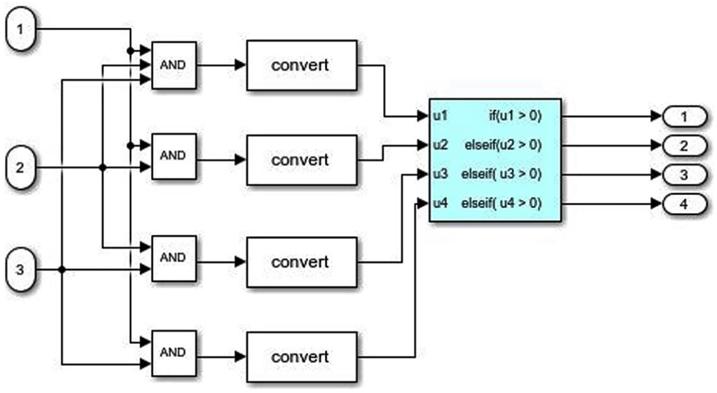
Control block of TMR model.
Detailed working of the output generated by the control block is summarized in Table 4.
TMR control block outputs.
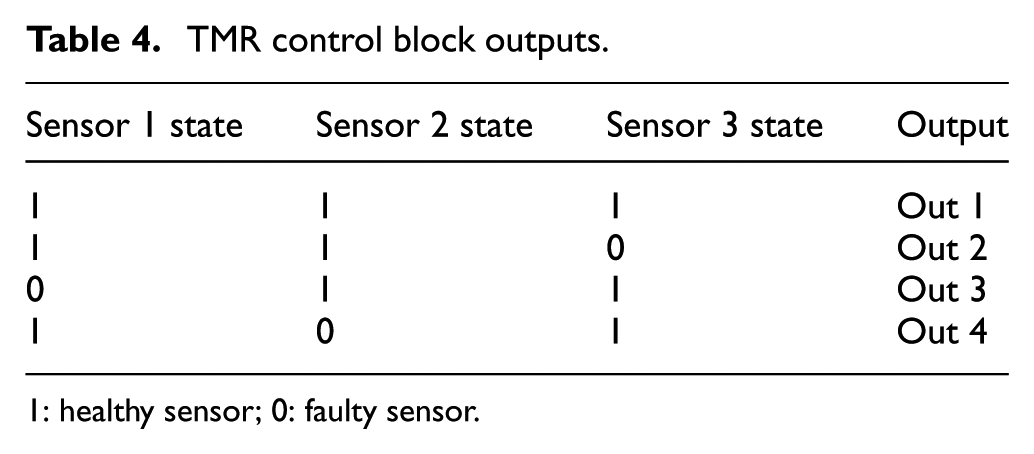
1: healthy sensor; 0: faulty sensor.
The output generated by the control block is fed to the voter circuit to generate an ultimate single output of the system. The port selection of the voter circuit is performed by the voter port selector as shown in Figure 26.
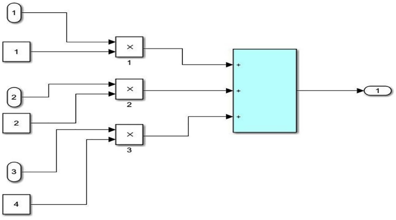
Voter port selection block of TMR model.
The number of ports generated by the voter port selector is summarized in Table 5.
Voter port selector working.
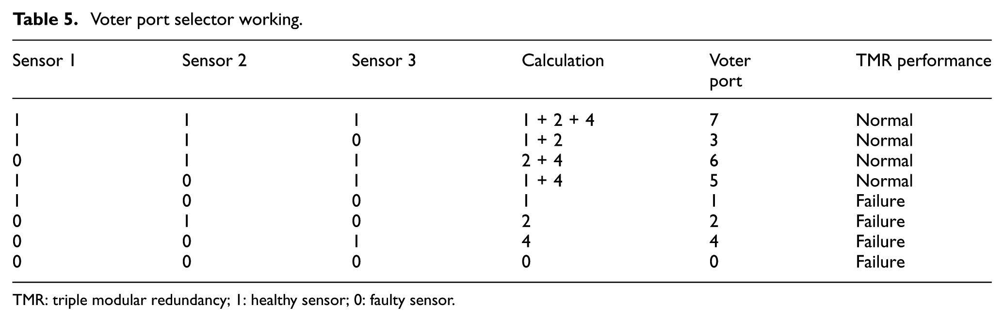
TMR: triple modular redundancy; 1: healthy sensor; 0: faulty sensor.
As evident from Table 5, the system remains normal with one fault in any of the three sensors of a single TMR assembly. In case of simultaneous failure of any two sensors, TMR assembly failure occurs. This is a limitation of the TMR architecture that it does not generate an output in case of simultaneous faults in two channels. The effect on the size of the engine due to the extra hardware is not covered in this study and has been mentioned in the future works.
Reliability analysis and comparison
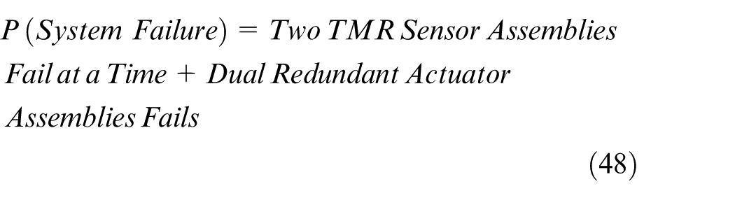
Brief reliability analysis of the proposed HFTCS is carried out to determine its reliability and compare it with that of the original MATLAB model. The probabilistic approach is used to determine the reliability functions of both models. It is assumed that failure events of more than one sensor that cause engine shutdown are mutually exclusive. First, we determine the reliability of the original model.
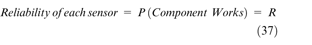
Let “R” denote the reliability of each sensor and actuator in the model, then

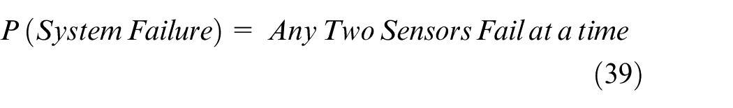
For four number of sensors, we will get the probability of failure of the original model as


The reliability of the overall original model is computed to be 96% with 90% individual reliabilities of the sensors and actuators.
Now the reliability of the proposed HFTCS is calculated. As determined in section “Introduction”, the reliability functions of TMR and dual redundant systems are as follows
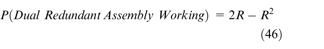
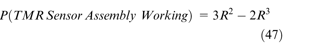
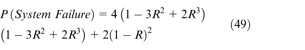


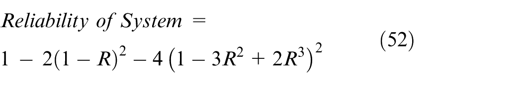
If R = 0.9 then
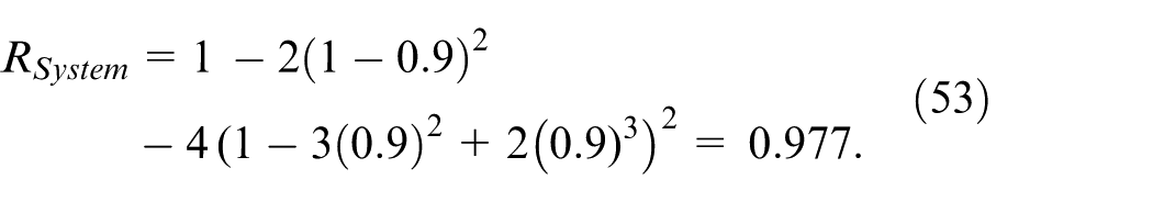

The reliability of the proposed HFTCS is computed to be 97.7 % which is greater than that of the original model.
The proposed HFTCS has many advantages over the existing model. First, it contains both AFTCS and PFTCS parts in their proper architectures, whereas the original model does not contain any proper FTC architecture. Second, system matrices have been calculated for the proposed system which may be used further for the application of linear control analysis techniques. These matrices are not available in the original model. Third, AFR degradation from 14.6 to 11.7 occurs in the original model in case of a fault in any sensor. This degradation has been made up for with the AFR controller in the proposed model, and AFR does not degrade under the faulty conditions. Fourth, the proposed model is more advanced in the sense that advanced FTC architecture and hardware redundancy scheme TMR is incorporated. Finally, the proposed model is more robust to faults and noise with greater reliability. It is able to continue its operation in case of simultaneous faults in more than one different sensor and actuator. Therefore, the proposed HFTCS with TMR in sensors and dual redundancy in actuators presents an optimum reliable solution for AFR control in SI IC gasoline engines.
Conclusion
In this paper, HFTCS was proposed for AFR control of IC gasoline engines based on KFs and advanced hardware redundancy scheme TMR for sensors. FDI unit was designed using KFs to provide estimated values to the controller in case of faults in sensors. A dedicated proportional feedback AFR controller was incorporated which controlled AFR by adjusting the throttle actuator in the fuel supply line in faulty conditions. Proposed HFTCS was tested with noise to check robustness. Simulation results show that the proposed system remains stable during faults in the sensors and actuators. It also maintains AFR without any degradation under faulty conditions and is robust to noise. Redundancy was proposed in the sensors to avoid engine shutdown by simultaneous faults in more than one sensor and actuator to avoid a single point of failure. Finally, the probabilistic reliability analysis of the proposed model was carried out and compared with the existing model. The study shows that the proposed HFTCS with TMR in sensors and dual redundancy in actuators makes the AFR control system highly reliable to prevent production loss by faults in sensors and actuators for decreased downtime and greater profits.
Future work directions may include the use of EKFs or PF to cover an entire nonlinear range of MAP with addressing partial faults in the sensors and actuators with convergence theory for stability. Another direction could be fulfilling the gap of conventional TMR system to enable working with the single healthy channel in case of simultaneous faults in the other two channels with the economic analysis justifying addition of extra hardware and determining the effect on the size of the engine for space optimization along with the experimental validation of the proposed model.
Footnotes
Declaration of conflicting interests
The author(s) declared no potential conflicts of interest with respect to the research, authorship, and/or publication of this article.
Funding
The author(s) received no financial support for the research, authorship, and/or publication of this article.