
Abstract
Fault-tolerant control systems are utilized in safety and critical applications to achieve greater reliability and availability for continued operation despite faults in the system components. These systems can be utilized in the process plants to avoid costly production loss due to abnormal and unscheduled tripping of the machines. In this paper, advanced fault-tolerant control systems of active type are proposed for air–fuel ratio control of internal combustion gas engine in a process plant to achieve greater reliability and availability to avoid a shutdown of the gas engine. Gas engines are extensively used equipment in the process industry and proper air–fuel ratio control in the fuel system of these engines is quite important to achieve greater engine efficiency, fuel energy savings and environmental protection. Active fault-tolerant control system is proposed in this paper in which linear regression–based observer model is used in the fault detection and isolation unit for fault detection, isolation and reconfiguration. Fuel actuator is introduced in the fuel supply line and proportional feedback controller is implemented to maintain the air–fuel ratio in faulty conditions. Redundancy in the sensors and fuel actuator is proposed to avoid engine shutdown in case of simultaneous faults in more than one sensor and to avoid a single point of failure due to fault in the single actuator. Noise is introduced in the sensor measurements to determine the robustness of proposed active fault-tolerant control system in noisy and faulty conditions. Results show that the proposed system remains stable, maintaining air–fuel ratio well in faulty conditions and is robust to noise.
Keywords
Introduction
Fault-tolerant control
Fault-tolerant control is an advanced approach to obtain greater reliability and availability in safety and critical applications such as unmanned air vehicles (UAVs), airplanes and nuclear facilities where system failure can cause human and environmental damages. These systems continue operation despite faults in the system components and prevent failure.1–3
Fault-tolerant control systems (FTCS) are classified into two major types based on differences in architecture and features: active and passive.2,4,5 In the active fault-tolerant control systems (AFTCS), faults are identified and isolated by a separate dedicated unit called as fault detection and isolation (FDI). FDI is the main component in AFTCS in which observer model is implemented to generate estimated values of various parameters of the system to compare with actual sensor values. Residual or difference is calculated and compared with defined bounds. If the error goes out of bound, a fault is declared in the component. After fault isolation, controller reconfiguration is performed for adaptation to new conditions.6–8 The architecture of AFTCS is shown in Figure 1.
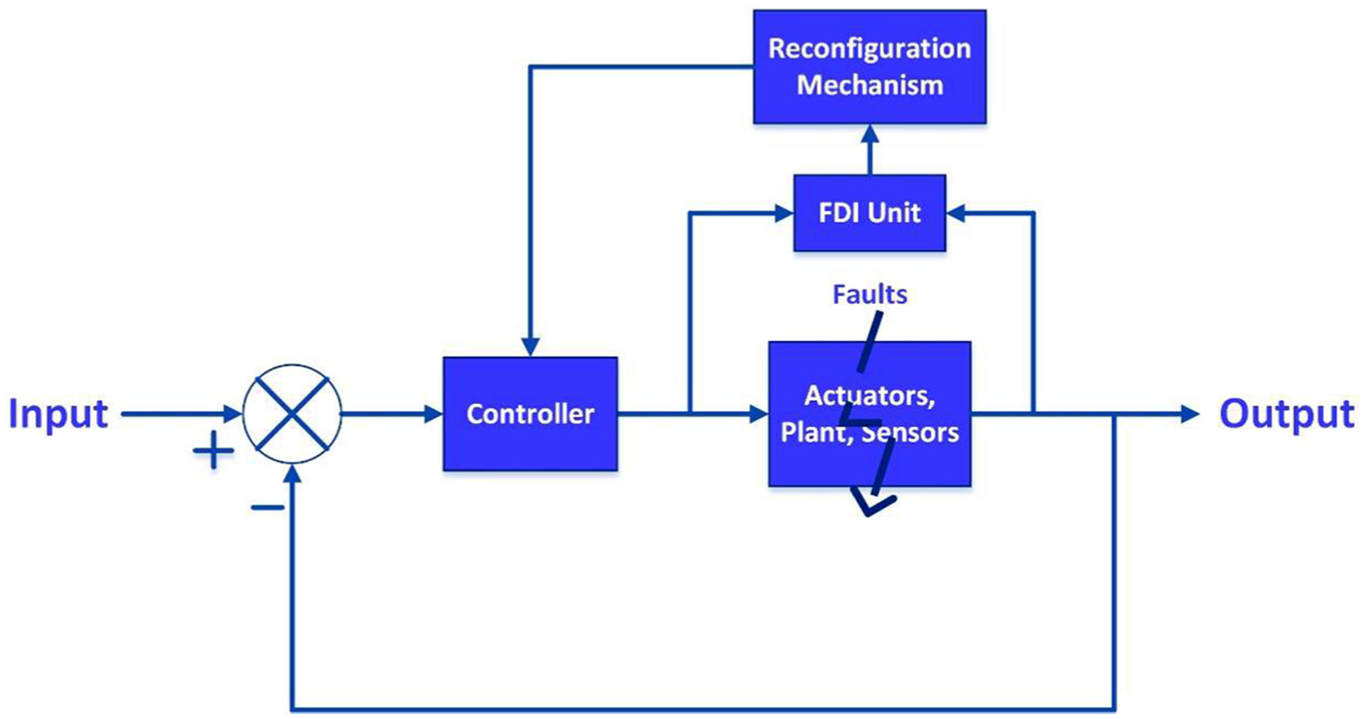
Architecture of AFTCS.
The observer design process is explained in detail by Wang et al. 7 and Nise 9 and is briefly described here.
In state space, the system can be expressed as follows

where “x,”“u” and “y” denote state, input and output vectors of the system. A, B, C and D are system matrices.
Let

Subtracting above equations, we get

Here,

We get the following equation for the observer

where L is the state feedback gain matrix. Now

The residual will determine the fault in the system component. If the residual goes to zero asymptotically, the system is stable with no fault. If the error goes out of the defined limit, a fault in the component will be declared.
Various techniques can be utilized in the design of FDI unit such as Kalman filters, fuzzy logic and neural networks. In the work by Yuan et al., 10 Kalman filters have been used for fault detection and location (FDL) for a nonlinear model of aeroengine in case of coexistence of sensor and actuator faults. In the work by Li and Tong, 11 fuzzy logic is used in FDI to estimate nonlinear function and adaptive control is implemented for bias and gain faults in the actuator. In the work by Tang et al., 12 AFTCS is designed using the neural network approach of average dwell time method and implemented to RCL (resistance, capacitance and inductance) circuit. In the work by Carbot-Rojas et al., 13 a nonlinear adaptive observer is designed using virtual sensor values in FDI to estimate flow rates for actuator fault for a double pipe heat exchanger.
In AFTCS, the controller works in online mode and can detect a wide range of faults. Disadvantages of AFTCS are that the system becomes complex and slow due to excessive computations. Moreover, noise can affect the decision-making process of FDI resulting in poor performance.14,15 In passive fault-tolerant control systems (PFTCS), a conservative controller is designed and all faults are considered in the design stage. PFTCS is fast as compared to AFTCS but can only mask faults defined in the design stage.16,17
To achieve robustness and desired response in a control system, feedback control technique is used. An example of robust control would be a high-gain feedback system in which parameter variation will not cause a significant impact on system performance due to high gains. Robust controllers maintain system stability without being affected by noise and parameter sensitivities.18–20 Popular feedback control techniques are proportional, integral and derivative (P, I, D); each action has its own benefits depending upon the suitability with the application under control. A set point is assigned to the controller and error is calculated from the set point and feedback from the sensor which is then subjected to these actions mostly in the form of P, PI and PID. The proportional action causes a proportional change with disturbance, integral action removes offset and derivative is anticipatory action. Controller action can be direct acting and reverse acting depending upon application under control. In the direct action, controller response increases with increasing error signal and in reverse action, controller response decreases with increasing error signal.21,22
Redundancy is one of the most important elements in FTCS and can be categorized into two types: hardware and analytical. In hardware redundancy, extra hardware is added to perform the same function as a backup component. In dual-redundant systems, the primary component performs all tasks and shifts to a backup component in case of any fault in it. Dual redundancy eliminates the single point of failure, which is defined as a condition in which fault in a single component can cause complete failure of the system. However, hardware redundancy causes an increase in cost, weight and physical size of the system. In analytical redundancy, a software model of the component is created to generate the virtual value of the sensor that can be used in case of a fault in actual hardware. Analytical redundancy can save costs, weight and physical sizes in certain applications such as UAVs and airplanes.23,24
Linear regression technique
Linear regression is a popular statistical technique to determine the relationship between dependent and independent variables to make a linear model.
The obtained relationship is of the following general type

where “y” and “x” denote vectors of dependent and independent variable values and “ε” denotes error or noise term. “β” denotes the values of partial derivatives of dependent variables with respect to various independent variables. This technique can be applied to a given set of data to determine the relationship between variables and future value can be estimated or forecasted based on the model obtained from the technique applied to the data. The strength of the model to fit with the observed data can also be determined using this technique. 25 Thus, this technique can be utilized in observer design in AFTCS due to its ability of estimation from the observation data set of the model. Microsoft Excel can be used to perform regression analysis on a given set of data as explained in regression in excel. 26 The main advantage of the method of linear regression is that it is not very complex computationally as compared to other FDI techniques and does not require system modeling parameters as it can be applied to the data to get linear functions of variables to be incorporated directly in the FDI. However, its limitation is that it is strongly dependent on the accuracy of the data and is usually accurate within a small linear range for most of the physical processes due to their nonlinear nature.25,27
Air–fuel ratio control
Internal combustion (IC) four-stroke gasoline engine is widely used equipment in the process industry as a prime mover for various applications such as generating sets, gas compressors and air compressors. 28
These engines convert chemical energy of fuel to mechanical rotational energy which is further applied to alternators and compressors. In IC engines, proper combustion of fuel and air is required to achieve advantages such as greater efficiency, energy savings and environmental protection. It is termed as stoichiometric combustion in which there is the proper ratio of air and fuel called as a stoichiometric ratio and its value is 14.6:1. Air–fuel ratio (AFR) can be expressed mathematically as follows
The combustion chemical equation is as follows

Dedicated controllers are utilized in these engines for AFR control as the mixture will not remain optimum and suitable for combustion if AFR varies. Mixture with AFR greater than 14.6 is termed as a lean mixture having less fuel and mixture with AFR less than 14.6 is termed as a rich mixture having excess fuel.29–31
Block diagram of the air–fuel mixing system of a spark ignition (SI) gasoline engine is shown in Figure 2. Air passes through the filter to remove dust and foreign particles and its flow is controlled by the throttle valve. Fuel is also filtered and its pressure is regulated as per engine requirement. Fuel actuator is also introduced in the fuel supply line to control AFR. Both air and fuel are then mixed and sent to engine cylinders for combustion. 32
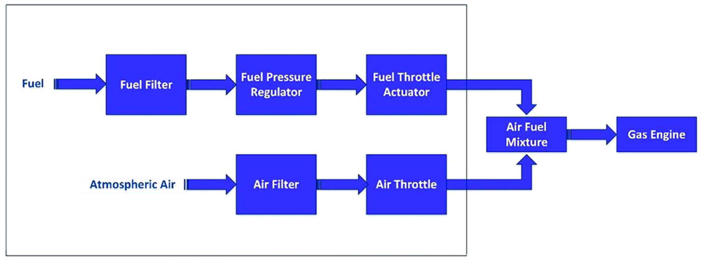
Block diagram of air–fuel system of SI IC gas engine.
The AFR control system is implemented in the engine controller to achieve the ratio of 14.6:1 for optimum combustion benefits. Faults in the sensors and actuators in the AFR system affect the performance of the engine and cause ultimately shutdown, thereby instigating interruption in the process. Therefore, it is highly desirable to make this system highly reliable to avoid tripping of the machine and prevent production loss.
Various approaches have been used for the design of AFR control in IC engines. In the work by Carbot-Rojas et al., 33 a survey on various aspects of IC engines is presented such as modeling, use of biofuels, simulation, supervision and different control laws. In the work by Pace and Zhu, 34 sliding mode control strategy is presented for AFR control. In the work by Lauber et al., 35 AFR control law is designed using nonlinear Takagi–Sugeno’s model. In the work by Anjum et al., 36 robust smooth super twisting algorithm (SSTA) is proposed for AFR control with reduced chattering effects. In the work by Wu and Tafreshi, 37 fuzzy sliding mode control (FSMC) is proposed for lean burn SI engine which is model free and does not need any system characteristic. In the work by Li et al., 38 PI-like fuzzy knowledge-based controller for AFR control is proposed that is capable of self-tuning and is highly robust. In the work by Gutiérrez León et al., 39 FDI for mass air flow (MAF) sensor based on an adaptive observer model is built to provide analytical redundancy for this sensor. In the work by García-Morales et al., 40 AFR control for E-10 hydrogen fuel is presented for the IC engine. In the work by Cervantes-Bobadilla et al., 41 a technique consisting of a combination of model predictive control (MPC) and PID control with the neural network is implemented to produce on demand hydrogen gas for SI IC engines.
Fault-tolerant fuel control system is implemented in Simulink that has analytical redundancy for sensors to provide estimated values from lookup tables during faults in the sensors. 42 This model is used in this research study for implementation of our proposed AFTCS. In this model, four sensors play a vital role in AFR control as described as follows:
Throttle position sensor. It provides air throttle valve position feedback to the engine controller.
Speed sensor. It provides a speed signal of the engine to the controller.
Exhaust gas oxygen (EGO) sensor. It provides the signal of oxygen content signal in the exhaust gas to the controller.
Manifold air pressure (MAP) sensor: It provides the signal of suction pressure in the air intake manifold. It is used in air density and mass flow calculations.
Faults are simulated in these sensors to confirm FTC behavior. In case of a fault in any one sensor at a time, the system continues to function using lookup tables to provide estimated values for the faulty sensor with degradation of AFR from 14.6 to 11.7. However, the simultaneous failure of any two sensors causes the shutdown of the gas engine.
Our contribution is the design of FTC for AFR control of SI IC gas engines using linear regression–based observer in the FDI unit with redundant sensors and actuators to achieve greater reliability due to both analytical and hardware redundancies. Such type of AFR control is not found in the literature so far up to our best knowledge. The advantages of the scheme are the less computational complexity of AFTCS design by applying the linear regression technique to the available data and independence from the system modeling parameters. The proposed technique is very much effective in terms of robustness to faults and noise as compared to other existing methods explained in modeling a fault-tolerant fuel control system 42 and has less computational complexity as compared to the works by Anjum et al., 36 Li et al. 38 and Gutiérrez León et al. 39 because of independence from the system modeling parameters. The limitation of the proposed technique is less accuracy of the estimated MAP parameter over a wide range due to the nonlinear behavior of the MAP sensor. Our assumption in this model is that the engine operates in the linear range of the MAP at 300 r/min. Sensor and actuator switching times in the hardware-redundant assemblies are also assumed to be 0 s.
Following contents of the paper are covered in three sections. Section “Research methodology” describes the experimental methods and section “Results and discussions” presents results and discussions. The conclusion of the study is presented in the last section.
Research methodology
FTCS is implemented at the air–fuel mixing system in the MATLAB and Simulink environment utilizing the available model and its preliminary working is explained in Modeling a Fault-Tolerant Fuel Control System. 42 Further work is carried out on this model by necessary modifications as per architecture of AFTCS and its results are presented. Statistical linear regression–based observer is implemented in FDI of AFTCS.
The engine speed is set to 300 r/min for this study and the same value is provided to the controller in case of a fault in the speed sensor, by the FDI unit. Data for the MAP and throttle sensors are obtained from the lookup tables available in the MATLAB model for 300 r/min. Then, statistical linear regression technique is applied to the data to obtain linear relationships between MAP and throttle using Microsoft Excel. These linear relationships are then used in the FDI unit to provide estimated values of the faulty sensors.
AFR in the original model gets degraded to 11.7 from 14.6 in faulty conditions. 42 A proportional feedback controller is implemented to avoid degradation and make the AFR control system robust to faults. It is given the set point of 14.6 with AFR as the input. It provides an output signal to the fuel actuator that is incorporated in the fuel supply line of the engine to adjust fuel in faulty conditions. Noise is introduced in the sensor measurements to check the performance of the controller in noisy conditions.
Faults in the sensors and actuators are simulated to check the performance of proposed AFTCS both in normal and noisy conditions. As per control logic implemented in original model, 42 a simultaneous failure of more than one sensor will cause engine shutdown; therefore, dual-redundant topology is proposed for sensors to prevent engine shutdown in that case. Single actuator failure in the fuel supply line will also cause a shutdown of the engine; therefore, the dual-redundant fuel actuator assembly is proposed. The proposed control system is designed to possess both analytical and hardware redundancies to provide an optimum novel reliable solution for AFR control.
Results and discussions
Performance of the proposed AFTCS without the AFR controller
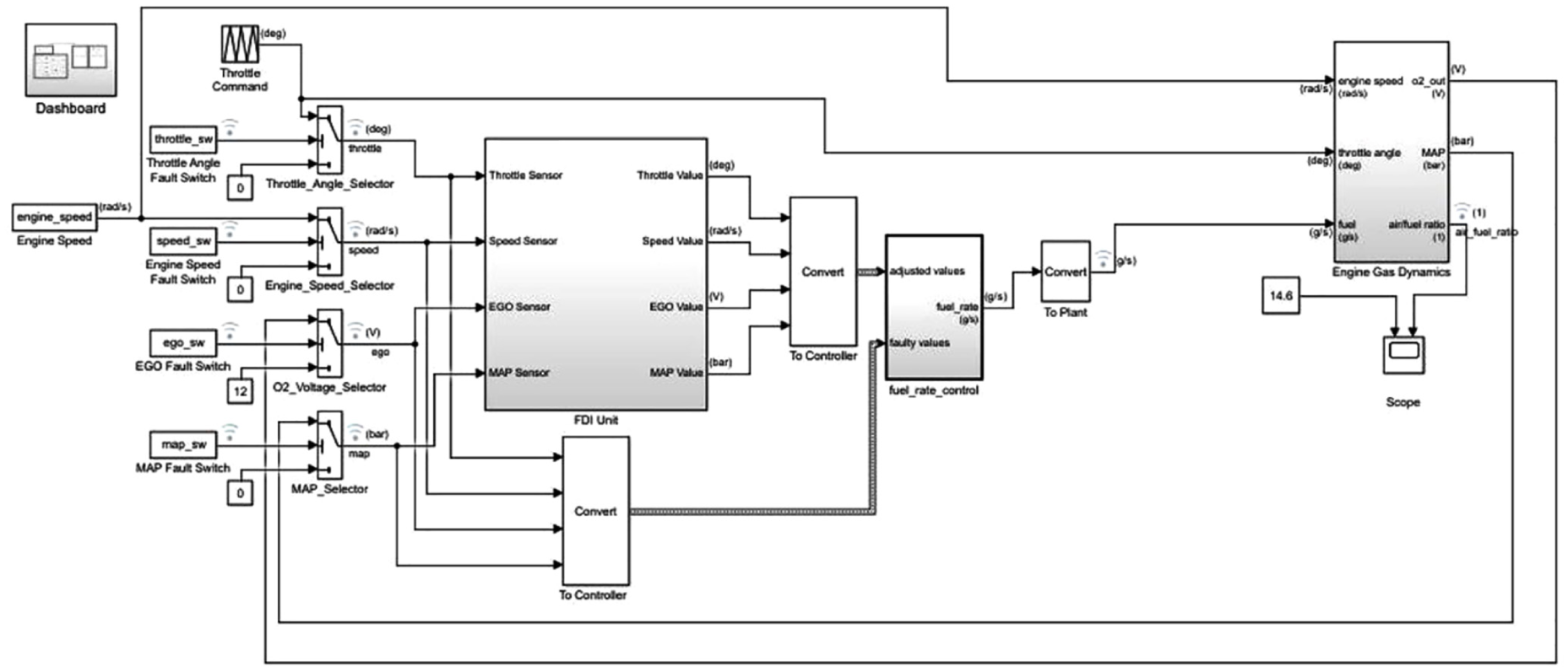
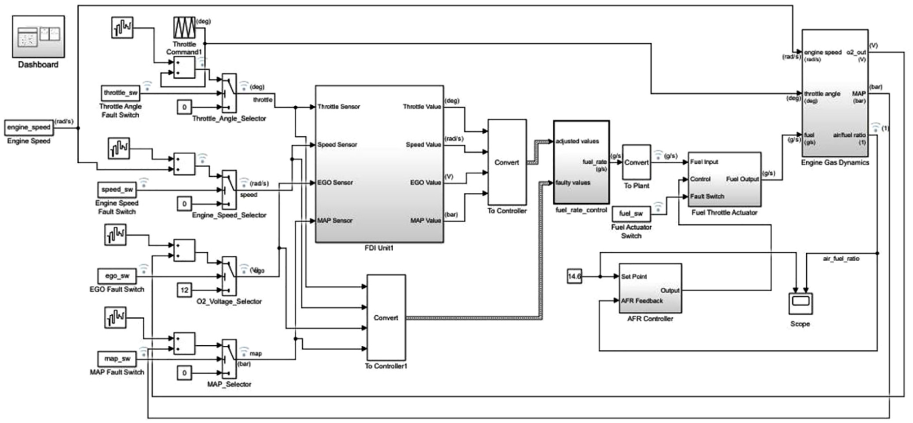
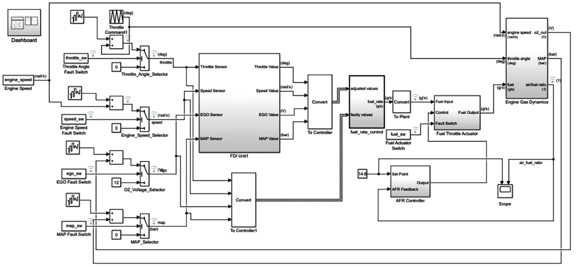
Implementation of the proposed AFTCS without the AFR controller in MATLAB IC Gas Engine model is shown in Figure 3. FDI block is created to detect, isolate and replace the faulty parameter with the estimated value.
AFTCS model implemented in MATLAB.
Internal block diagram of FDI is shown in Figure 4.

Fault detection and isolation (FDI) unit block.
FDI block further consists of reconfiguration and estimation block shown in Figure 5.
Internal blocks in FDI unit.
The fault estimation unit is designed using the statistical linear regression technique on the data obtained from lookup tables of the model. The speed of the engine is assumed to be 300 r/min; therefore, speed estimation is not performed. The values of the throttle and MAP sensors are taken for this speed. Data for MAP estimation for 300 r/min are shown in Table 1.
MAP and throttle angle relationship for 300 r/min.
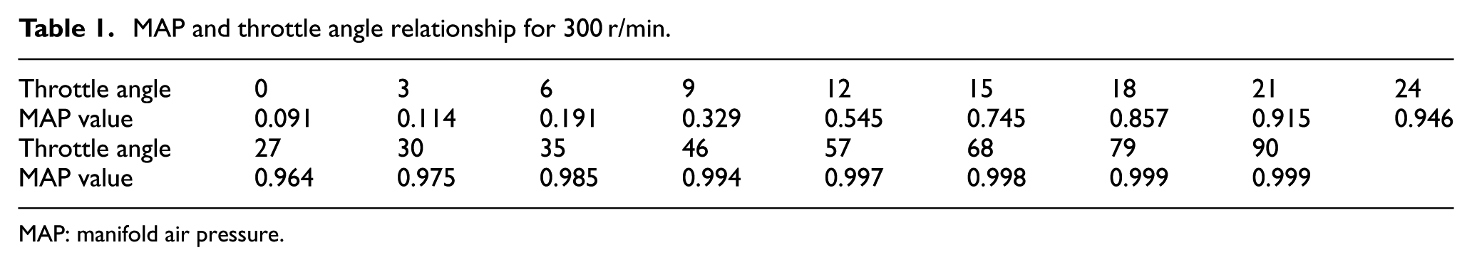
MAP: manifold air pressure.
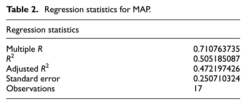
Regression analysis is carried out on this data in Microsoft Excel and the results of the statistics are shown in Tables 2 and 3.
Regression statistics for MAP.
Regression coefficients for MAP.
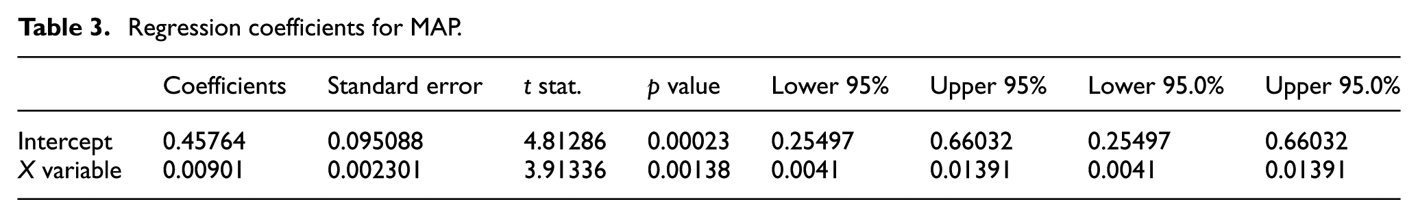
The equation for the regression model for the MAP is obtained as follows

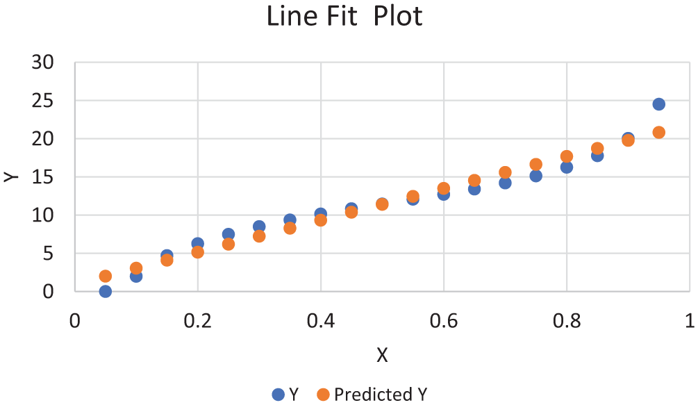
where “y” denotes MAP-estimated value and “x” denotes throttle angle. The line fit plot of the estimated model’s value with the lookup table data is shown in Figure 6.
Line fit plot for MAP-estimated values.
Data for throttle estimation for 300 r/min are shown in Table 4.
Throttle angle and MAP for 300 r/min.
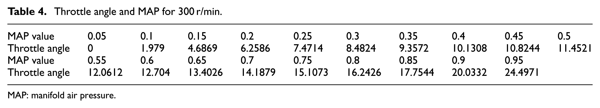
MAP: manifold air pressure.
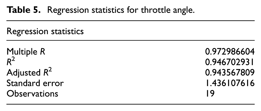
Regression analysis is carried out on this data in Microsoft Excel and the results of the statistics are shown in Tables 5 and 6.
Regression statistics for throttle angle.
Regression coefficients for throttle angle.
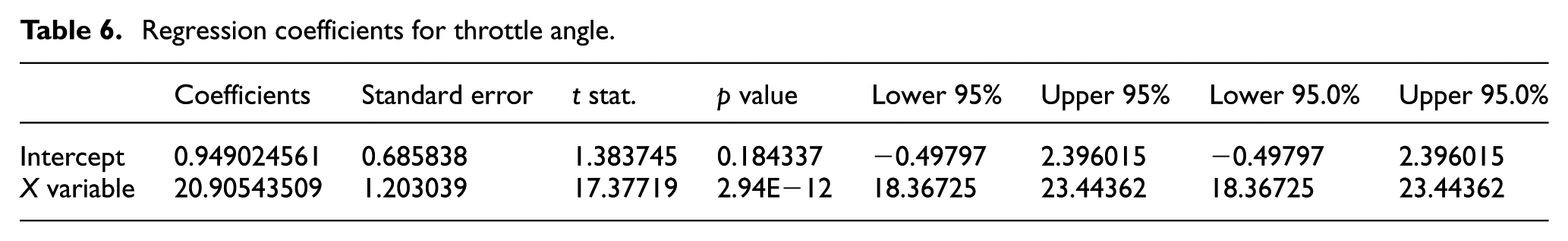
The equation for the regression model for throttle angle is obtained as follows

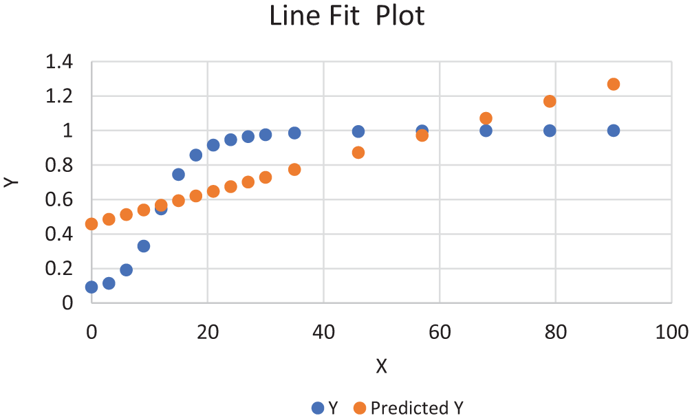
where “y” denotes the throttle angle estimated value and “x” denotes the MAP value. The line fit plot of the estimated model to lookup table data is shown in Figure 7.
Line fit plot for throttle angle–estimated values.
Internal diagram of estimation block is shown in Figure 8.
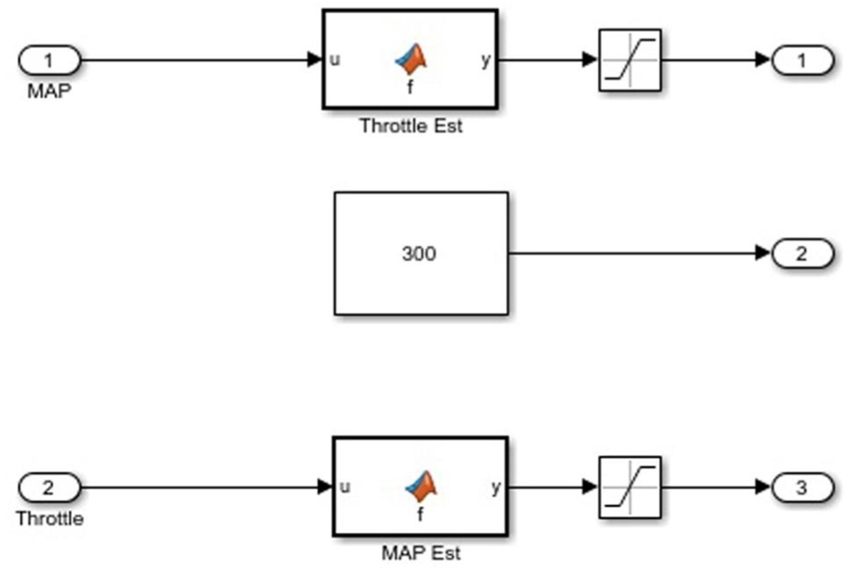
Internal diagram of estimation block.
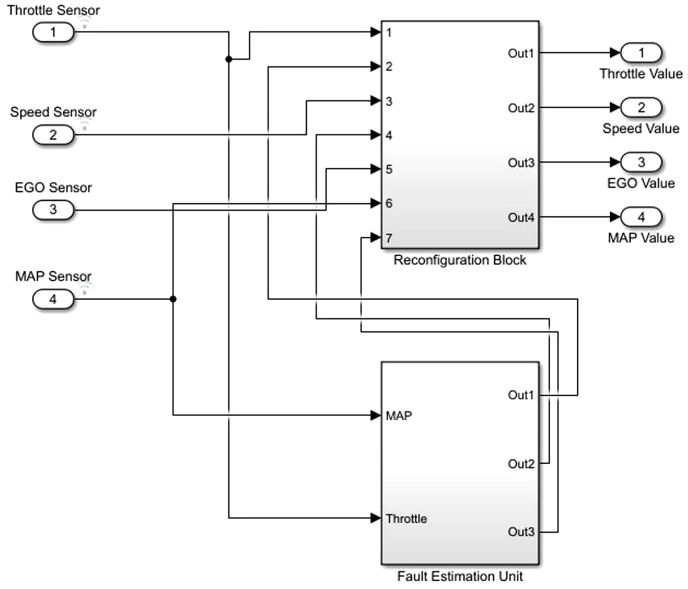
Internal diagram of reconfiguration block is shown in Figure 9. It calculates the residual and determines its bounds. If the residual remains within bounds, it passes sensor value to the controller. In case of a fault in the sensor, the residual becomes out of bound and faulty sensor value is replaced by the estimated value obtained from the estimation block and supplied to the controller.
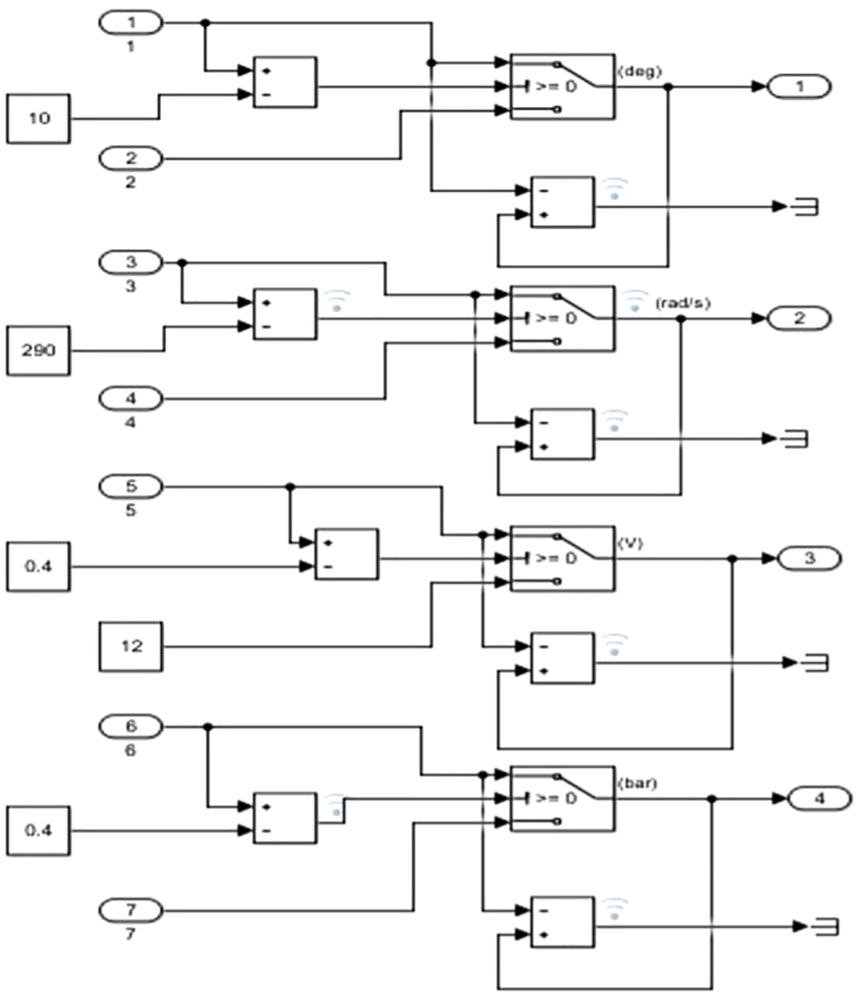
Reconfiguration block of FDI unit.
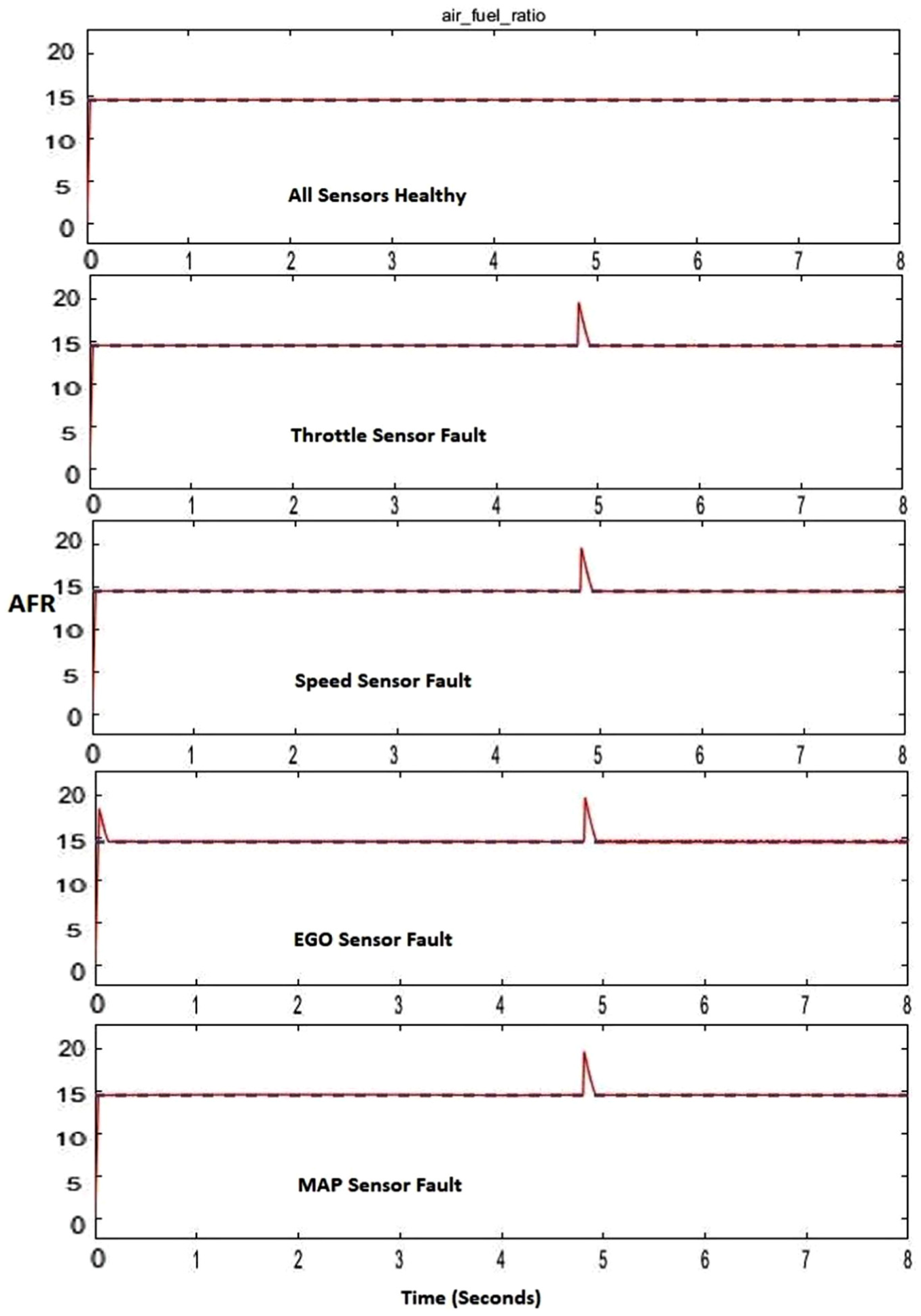
The performance of the proposed AFTCS in normal and faulty conditions is shown in Figure 10. A fault is introduced in each sensor one by one individually.
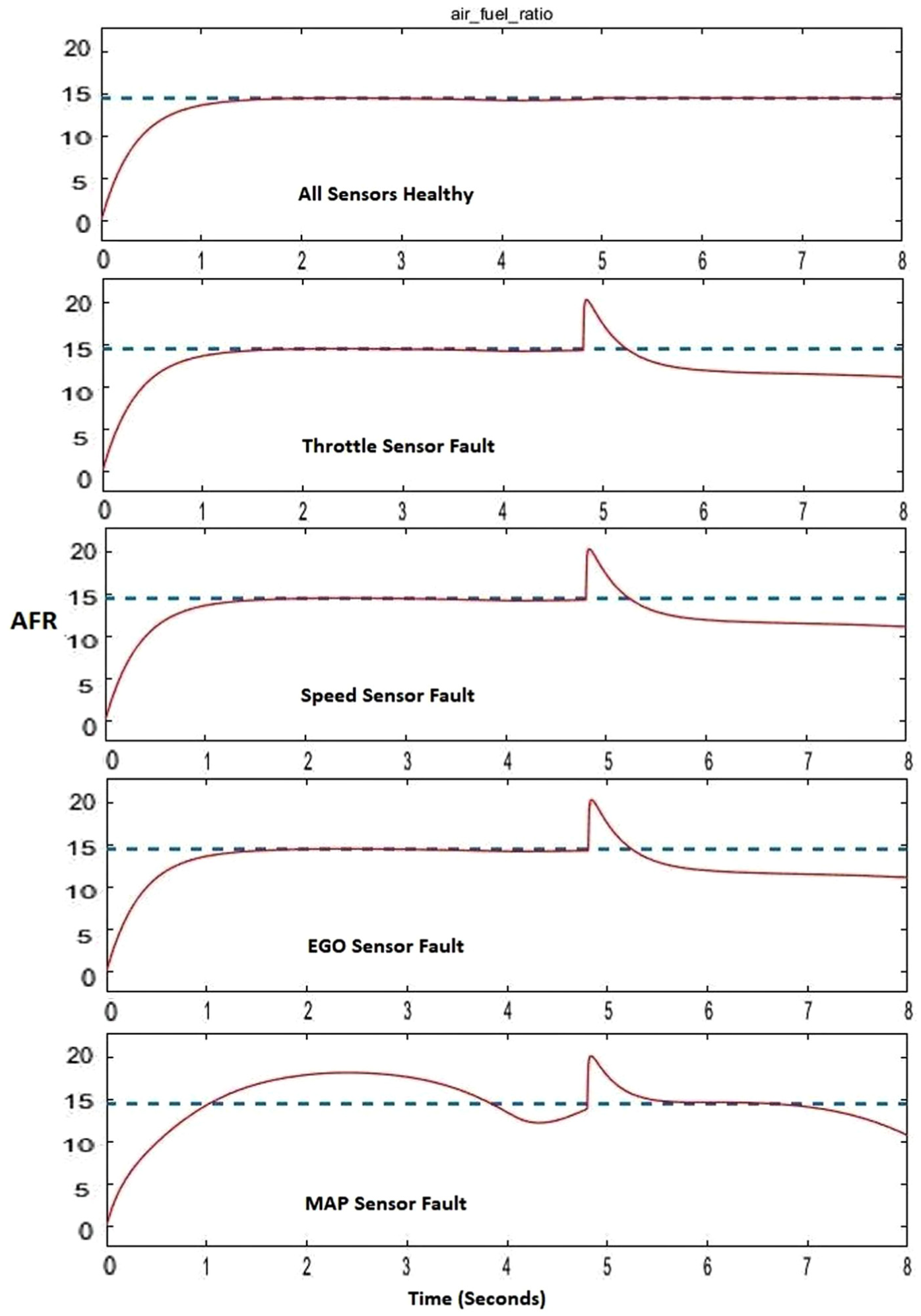
Performance of proposed AFTCS in faulty conditions.
Implementation of AFR controller
Results of Figure 10 show that AFR is affected by faults in any one sensor at a time and decreases to 11.7. Therefore, a proportional feedback controller with fuel actuator is introduced in the model as shown in Figure 11 to maintain AFR to 14.6 in faulty conditions.
AFR controller and fuel actuator incorporation in model.
The internal working of fuel actuator is shown in Figure 12.
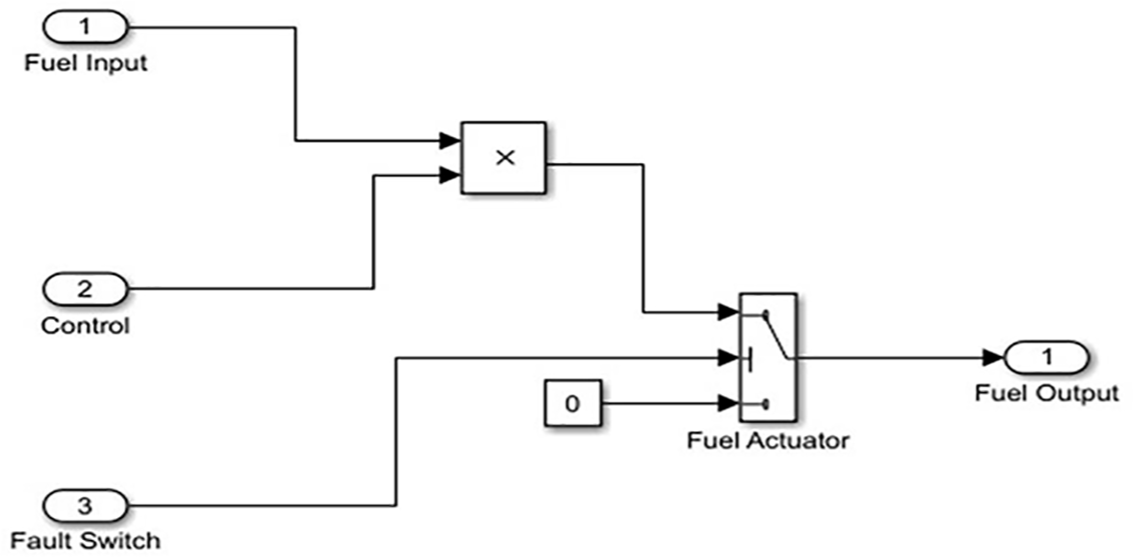
Fuel actuator model.
The internal working of the AFR controller is shown in Figure 13.
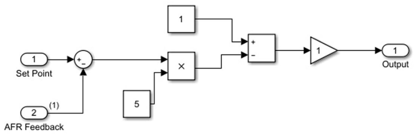
AFR proportional feedback controller.
AFR controller maintains AFR to 14.6 in normal as well as faulty conditions as shown in Figure 14.
Performance of AFTCS with AFR controller.
Results of Figure 14 show that proposed AFTCS with AFR controller is robust to faults in the sensors. Hence, the degradation of AFR is prevented.
Introducing noise in the sensor measurements
Noise is introduced in the sensor measurements to check the robustness of the proposed AFTCS as shown in Figure 15.
Introduction of noise in the model.
Noise parameters for throttle and speed sensors are shown in Figure 16.
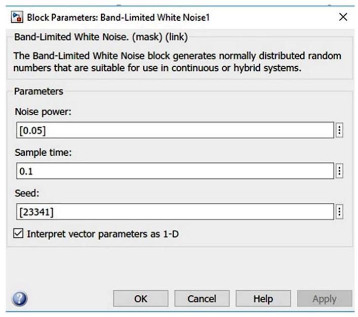
Noise parameters for throttle and speed sensors.
Since EGO and MAP sensors are of very low value ranging from 0 to 1, low noise is introduced in these sensors to keep values within bounds defined for fault as shown in Figure 17.
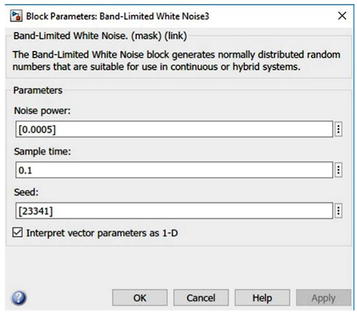
Noise parameters for EGO and MAP sensors.
Greater noise values in the sensors will cause sudden variations of measurements out of bounds and will produce the wrong decision of fault conditions. Performance of proposed AFTCS with noise is shown in Figure 18.
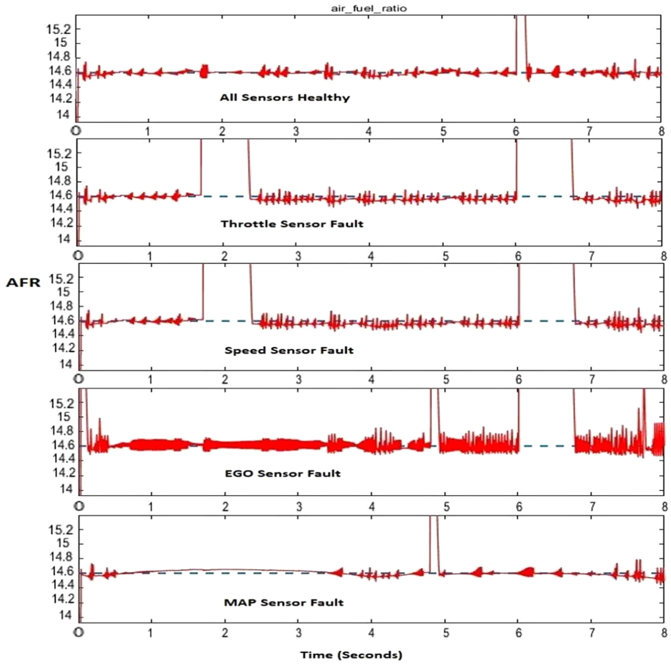
Performance of proposed AFTCS in noisy conditions.
Results of Figure 18 show that proposed AFTCS with AFR controller is robust to noise in normal and fault conditions by maintaining AFR to 14.6.
Introducing redundancy in the sensors and actuators
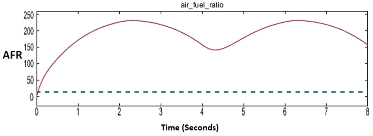
Simultaneous faults in more than sensors cause a shutdown of the engine and abrupt increase in AFR due to cutting off of the fuel supply as shown in Figure 19.
AFR in case of simultaneous faults in more than one sensor.
To prevent a shutdown of the engine in this condition, the redundant sensor assembly (RSA) is proposed for all sensors. A fault in the primary sensor 1 will cause switching to secondary or backup healthy sensor 2 online as shown in Figure 20.
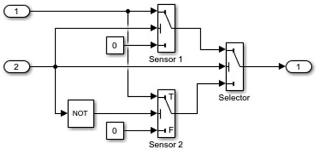
Redundant sensor assembly.
AFR remains 14.6 for simultaneous fault in more than one sensor with RSA as shown in Figure 21. Switching time of the sensors is assumed to be zero in this simulation study.
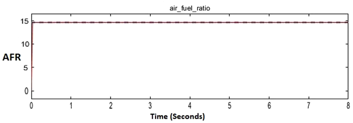
AFR in case of simultaneous faults in more than one sensor with redundant sensor assembly (RSA).
The dashboard of the model is updated to simulate a fault in actuator as shown in Figure 22.
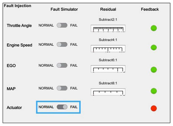
Dashboard update for actuator fault simulation.
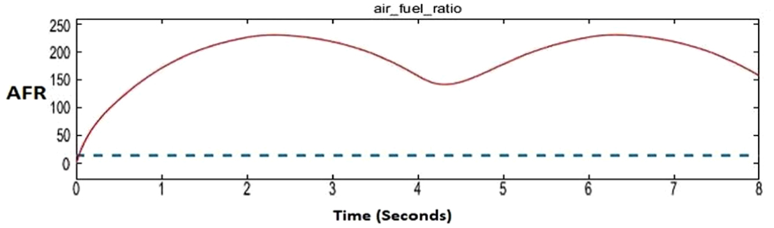
A fault in the single-fuel actuator causes the closing of actuator and cuts off the flow of fuel to the engine. Therefore, AFR increases drastically as shown in Figure 23.
AFR in case of single-fuel actuator fault.
The dual actuator assembly is proposed for the engine as it prevents a shutdown of the engine in case of a fault in one online primary actuator as shown in Figure 24. Secondary or backup actuator comes into operation quickly. Switching time is assumed zero in this simulation.
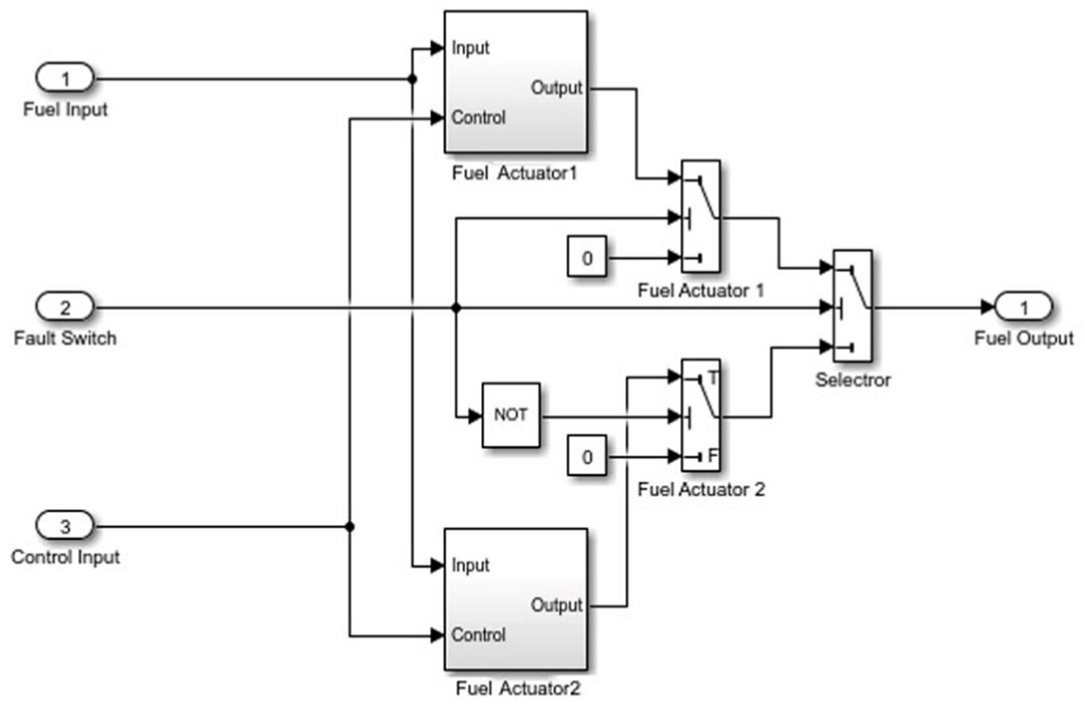
Redundant fuel actuator assembly.
AFR is maintained in this case as shown in Figure 25.
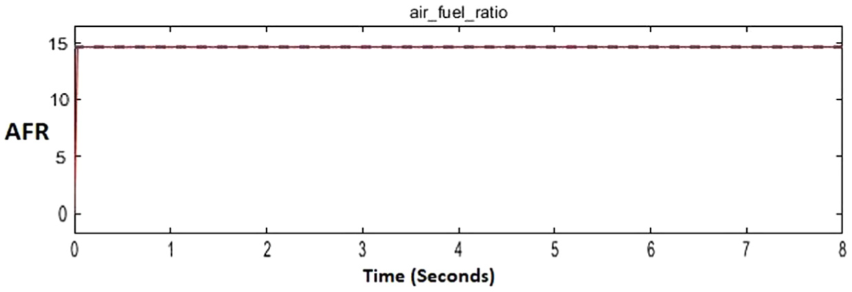
AFR in case of redundant fuel actuator fault.
Comparison with the existing model
Comparison of the proposed approach with the existing MATLAB model of IC engine is made and gaps in the existing model are identified. In this study, several contributions are made to fulfill these gaps. First of all, the existing model does not have a proper FTC structure since a dedicated FDI unit is missing in it. We have developed a proper AFTCS architecture in our model with a dedicated FDI unit. Second, the existing model produces estimated values of the faulty sensors from the lookup tables that are nonlinear making the overall model a nonlinear one. Therefore, linear control techniques cannot be applied directly. We have used linear regression method to produce linear relationships for the MAP and throttle sensors from these nonlinear lookup tables; thus, our model becomes a linear one and linear analysis techniques can thus be applied for further research. Third, the MATLAB model does not have a fuel throttle actuator in the fuel supply line which is an essential component in the practical IC gas engines. We have incorporated that actuator in our model and implemented an efficient AFR controller through this actuator. Fourth, we have implemented redundancy in the sensors and actuators to enhance the reliability of the engine and it makes our model much more reliable than the existing one. Finally, the proposed model is more robust to the faults and noise without suffering from degradation of AFR in faulty conditions.
Conclusion
FTCS are highly reliable control systems for continued operation despite faults in the system components. These systems can be utilized in process plants to avoid costly production loss due to abnormal and unscheduled tripping of the machines. In this paper, advanced FTCS of active type has been proposed for AFR control of IC gas engine in a process plant to achieve greater reliability and availability to avoid shutdown due to faults in sensors and actuators. AFTCS is proposed in which a linear regression–based observer model is used in the FDI unit for fault detection, isolation and reconfiguration. Fuel actuator is introduced in the fuel supply line and proportional feedback controller is implemented to maintain the AFR in faulty conditions. Redundancy in sensors is proposed in the control system to avoid engine shutdown in case of simultaneous faults in more than one sensor. Redundancy in the actuator is proposed to avoid a single point of failure due to fault in the single actuator. Results show that the proposed system remains stable, maintaining AFR well in faulty conditions and is robust to noise.
Future research work may include the use of advanced nonlinear regression techniques in the FDI design for advanced analytical redundancy with convergence theory to support experimental results. Advanced hardware redundancy techniques such as triple modular redundancy (TMR) may also be considered in combination with analytical redundancy with the justification of additional cost over benefits.
Footnotes
Declaration of conflicting interests
The author(s) declared no potential conflicts of interest with respect to the research, authorship and/or publication of this article.
Funding
The author(s) received no financial support for the research, authorship and/or publication of this article.