
Abstract
This paper proposes a novel hybrid fault-tolerant control system (HFTCS) with dedicated non-linear controllers: artificial neural network (ANN) and sliding mode control (SMC) for active and passive parts, respectively. The proposed system can provide both desirable properties of stability to unexpected fast disturbances and post-fault optimal performance. In the active fault tolerant control system (AFTCS) part, the fault detection and isolation (FDI) unit is designed through the use of ANN for the estimation of faulty sensor values in the observer model. In the passive fault-tolerant system (PFTCS) part, the air-fuel ratio (AFR) controller is designed using a robust SMC that allows systems to manage faults in predefined limits without estimation. In the proposed system, SMC will form the passive part to react instantly to faults while ANN will optimize post-fault performance with active compensation. Moreover, Lyapunov stability analysis was also performed to make sure that the system remains stable in both normal and faulty conditions. The simulation results in the Matlab/Simulink environment show that the designed controller is robust to faults in normal and noisy measurements of the sensors. A comparison with the existing works also demonstrates the superior performance of the proposed hybrid algorithm.
Keywords
Introduction
Fault-tolerant control and its types
Fault-tolerant control systems (FTCS) are regarded as modern control systems to achieve higher reliability and stability. A fault is classified as a deviation from the standard operating value of a plant parameter. Faults in a system can jeopardize the desired operation of the whole system. An FTCS may work under faulty conditions and stay stable; however, performance loss can occur. The FTCS may also be used to maintain stability because of the safety of people, and mission-sensitive applications like aircraft, and unmanned air vehicles (UAVs).1–3 Due to variations in architectures and properties, FTCS is divided into two major categories: active and passive. Some symbols and abbreviations related to HFTCS are listed in Tables 1 and 2, respectively.
List of abbreviations.

List of symbols.

In active fault-tolerant system (AFTCS), the fault detection and isolation (FDI) unit is designed to detect the fault in the online mode and it isolates faulty values.4–6 The FDI unit compares the values of the actual sensors with the estimated values being generated from the observer for a residual generation. The fault in the component is declared when the residual value exceeds its predefined limiting value. The controller is then reconfigured to adapt according to the current faulty conditions after fault detection and isolation, with little output deterioration.7,8 Unlike AFTCS, passive fault-tolerant system (PFTCS) may not need a dedicated FDI unit, and any fault in the design stage of the control system is considered beforehand in the offline mode.9–11 PFTCS is, therefore, very swift than AFTCS due to lesser computational cost, but it has the drawback to deal with the faults only that were considered during the construction of the controller.12,13 A combination of all these approaches is also built by integrating both types, namely hybrid fault-tolerant control system (HFTCS). In protective and safety applications, the hybrid system can rapidly respond to faults with the PFTCS property and later optimize itself with the AFTCS property.14–16 In Amin, 14 the HFTCS has been proposed with Kalman Filters in the active part and a high-gain PI controller in the passive part. This algorithm was limited to the linear range of the highly nonlinear sensors of the AFR control system. In Su et al., 15 the HFTCS was proposed for the sensors of the distillation column without using any intelligent control or data-driven technique. In Wang et al., 16 the HFTCS was proposed for the uncertain networked control systems under a discrete event-triggered communication scheme that was not applied to the process plant.
A comprehensive study of the FTCS has been mentioned for the nonlinear system in Li 17 for various fault scenarios. In Yang et al., 18 the non-linear hybrid FTCS design was established for feature extraction, and the actuator fault adjustment control was applied. The artificial neural networks (ANN) technique was applied for the switched-type nonlinear systems in Tang et al.. 19 For a single-tank system with system faults and process disturbances, a fuzzy logic-based passive fault-tolerant control method was proposed in Patel and Shah. 20 In Murtaza et al., 21 a super-twisting control-based unified FDI and FTC system for the air path of diesel engines is reported. Kalman Filters (KFs) were also used in the FDI architecture of gas turbines for faulty sensor estimation22,23 consisting of both hardware and analytical redundancies.
Artificial neural networks
The artificial neural network (ANN) includes the concept of artificial intelligence, whose aim is to allow the systems to learn from experience. ANN works on the same logic as a human brain. It is a smart and modern approach to data-driven problems. 24 This non-linear technique is used in real-time problems like the modeling of the engine because the engine is a highly non-linear system and ANN provides an optimal solution for such highly nonlinear problems.25–27 The architecture of the ANN is shown in Figure 1.

The architecture of ANN. 24
ANN performs a data-parallel function, therefore, sequential simulations are easier than standard systems. The ANN works with both forward and backpropagation. Its multi-layer perceptron model is known as a backpropagation neural network (BPNN).28–30 The input is in the form of samples and is treated with different multiple hidden layers before the required output is mapped through this input. In Gao et al., 30 FTC architecture was proposed with an adaptive neural network for Multi-Input Multi-Output (MIMO) systems. In Wang et al., 31 the ANN is utilized with a backpropagation strategy for the fault-tolerant control system. An adaptive neural network for the unmolded dynamic solution is proposed in Yin et al. 32 The dataset is mapped to real numbers, that is, (x, y) where x represents the selected feature and y translates the health state to this feature. ANN is described in terms of mathematical form is,

where
Sliding mode control
Robust control is a control system architecture technique that can allow systems to manage faults as long as the faults stay within the predefined limits.33,34 Robust control systems are static rather than dynamic and do not adjust to their conditions. For example, a high-gain feedback system is a robust control system due to its high gain, and changes in the other parameters prove negligible due to its robustness. Sliding mode control (SMC) is derived from a variable structure control system that mostly incorporates various control structure features and performs better than existing classical control structures.35,36 There are two phases in the SMC design as represented in Figure 2.
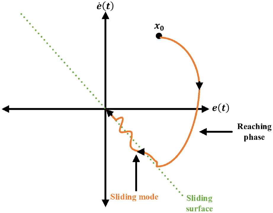
Sliding mode control. 33
SMC triggers chattering in the actuator because of the rapid switching, therefore, a higher-order SMC named as super twisting algorithm is used to reduce the chattering problem. 37 It is a non-linear technique with exceptional robustness properties. In practical terms, SMC facilitates non-linear processes that are subject to large model uncertainties. SMC will form the passive part in our proposed HFTCS to react instantly to faults. 38
A customizable surface needs to be built in the first phase. The second phase should be planned to ensure that the system converges to the sliding surface for a minimum time. The phenomenon in which the motion takes place on a sliding surface is known as a sliding mode. 38
AFR control of IC engines
The internal combustion engine is a type of heat engine in which the combustion of air and fuel takes place inside the cylinder and is used as the direct motive force. These engines transform the chemical energy of a fuel into thermal energy and use this energy to produce mechanical work. Its two main types are known as Spark Ignition (SI) and Compression Ignition (CI). In SI engines, the combustion takes place with the help of spark plugs, while in CI engines, the heat of compression is used for combustion. 39
The term air-fuel ratio (AFR) is defined as a mixture ratio of proper fuel and air in the combustion chamber and it is widely used to enhance the reliability and efficiency of the IC engine. Its mathematical expression can be written as:

where

According to this equation, AFR is said to be the stoichiometric ratio with a value of 14.6:1 for gasoline fuel and is desirable for optimum combustion, fuel energy savings, and reduced emissions levels. If the mixture has AFR greater than 14.6:1, it is known as a lean mixture with greater air than fuel. A mixture with lesser than 14.6:1 is termed a rich mixture with greater fuel than oxygen. However, both of them are considered to be harmful to the engine’s performance and life as it decreases their efficiency. The value of AFR is different for various categories of fuels. For example, methanol values are 6.47:1, 9:1 for ethanol, and 34.3:1 for hydrogen. 40
The air-fuel mixing system of an SI IC engine is shown in Figure 3. Atmospheric air is filtered first and then passes through a throttle actuator. To change AFR more accurately by the AFR controller, the fuel actuator has been designed to adjust the fuel supply. The fuel is then first purified and transferred to the fuel actuator for flow control via the fuel pump. Air and fuel mixture is then made and provided for combustion to the engine cylinders.

Air-fuel ratio control of an SI IC engine. 39
In the AFR control system of the IC engine, four sensors play an important role.
Throttle sensor: Often known as an air sensor. It provides the air throttle position signal to the engine control unit (ECU).
Manifold absolute pressure (MAP) sensor: It is also called a pressure sensor. It provides the suction manifold air pressure value to the ECU.
Speed sensor: It measures the speed of the engine crankshaft and provides to the ECU for controller calculations.
Exhaust gas oxygen (EGO) sensor: It’s often referred to as a gas sensor. The concentration of oxygen in the exhaust of the IC engine is measured by an EGO sensor and provided to the ECU.
In the paper, our contribution is to implement the novel HFTCS for the reliable operation of the IC engine to maintain the AFR in faulty conditions and prevent engine shutdown. In the proposed system, SMC will form the passive part to react instantly to faults while ANN will optimize post-fault performance with active compensation. Lyapunov stability analysis was performed to make sure that the system remains stable in both normal and faulty conditions. The fault tolerance is checked with noisy measurements of sensors to examine the robustness of the proposed controller. The simulation results in the Matlab/Simulink environment show that the designed controller is robust to faults in normal and noisy measurements of the sensors and reliable. Furthermore, the comparison with the existing works is carried out to demonstrate superior performance.
The structure of paper is organized as. Section “Research methodology” discusses the research methodology. Section “Results and discussions” presents the results and discussions. Section “Comparison with the existing works” elaborates on the comparison. Finally, the last section provides the conclusion of the paper.
Research methodology
The proposed HFTCS is implemented on the available IC engine model in Simulink. Mathworks explains preliminary knowledge and model working.41,42 In this model, the AFR system of the gasoline engine is built based on the findings of Crossley and Cook 43 and was fully validated against dynamometer test data. 42 The mathematical equations used for the model construction are in accordance with the mean value engine model (MVEM). 44 Moreover, it gives accurate AFR as found in practical gasoline engines. 40 HFTCS is a combination of AFTCS as well as PFTCS, as previously mentioned. AFTCS is designed using an ANN-based observer to build the FDI unit. In PFTCS, the AFR controller is designed using a robust SMC that allows systems to manage faults without many computations. The engine speed for this study is set at 300 r/min due to the design speed of the available MATLAB engine model. Therefore, a value of 300 is transmitted to the controller by the FDI unit in the case of a fault in the speed sensor. We utilized constant speed in this study since the engines in the process plant run at a constant speed most of the time, and the designed FDI provides the controller with 300 r/min of speed if the speed sensor fails. Because the paper is focused on designing an ANN-based AFTCS system, load changes and their impact on speed are not examined. The data for the MAP sensor and the throttle sensor at 300 r/min is derived using the available Matlab model lookup tables (LTs). To generate nonlinear interactions between the MAP sensor and the throttle sensor, the ANN approach is applied. For the generation of the estimated value of malfunctioning sensors, the FDI unit uses these nonlinear relationships. If the throttle and MAP sensors are faulty, the FDI unit generates an estimated value based on ANN observations and supplies to the ECU. The important parameters used in the model are mentioned in Table 3:

First of all, the engine can work in its normal conditions if there is no fault. On the other hand, if a single sensor fault will happen, SMC will form the passive part to react instantly to faults while ANN will optimize post-fault performance with active compensation. Noise is introduced into the sensors, and their effect on the output is seen in normal as well as in faulty conditions to check the robustness of the proposed HFTCS. Zero seconds have been assumed when the sensors are switched. However, a delay possibly occurs in the switching actions. The limitations of the work are that only the full fault for sensors is carried out without taking partial faults which will be covered in future works.
Engine AFR system modeling
The modeling mentioned in this section is generic for complete theoretical analysis and adopted from well-known literature.40,45 The control of the air-fuel ratio is divided into different dynamics: air dynamics, sensor model, and fuel dynamics.
Air dynamics
The dynamic manifold intake is defined by the mass conservation theory and ideal air gas hypothesis in the following terms:


Where,

The mass flow through the valve is:


where

Fuel dynamics
It is represented as:

Where


Where
The air-fuel ratio is then obtained:

Sensor model
The lambda sensor model is represented as:

where
The time delay

State-space representation
It is represented as:

With


Here “
Controller design
The controller design is adopted from Sui and Hall 46 and given below:


Where the input is

where

Where the predicted output is


Equation (25) shows the mean square error function, so if we take the partial derivative of the previous equation,

The gradient descent algorithm can change the state variables,


Where the estimated inputs are


Add the value of
Lyapunov stability analysis is performed to check the system’s stability. Let’s assume the Lyapunov function is,

Put the values of actual and desired outputs in equation (34),

The error estimation is,


So the Lyapunov function is,

If we change

Where,


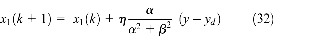
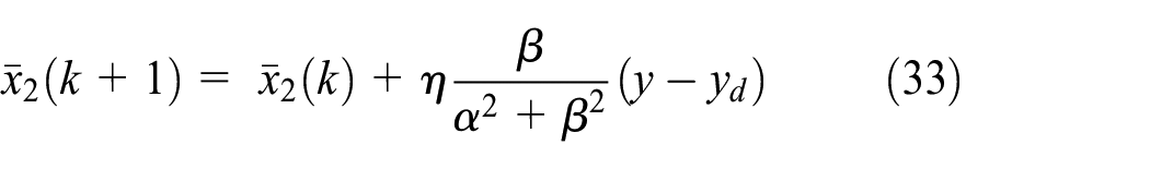
Adding equations (32) and (33) into the (40) and (41) as follows,

Taking the difference between actual and predicted output is,


The Lyapunov function can be written as,

So, the difference between both of them is,


The last equation shows that the difference between both cycles is negative definite and hence the Lyapunov stability proof is successfully achieved. The observer design with ANN was already discussed in Shahbaz and Amin 4 for the AFTCS part.
SMC mostly incorporates various control structure features and facilitates non-linear processes that are subject to large model uncertainties. SMC will form the passive part to react instantly to faults. Consider the MIMO system,


Where

Where

Consider sliding surface:

Where


We can write as:

Where

Where

Where

The remaining system can be handled over:


Unstructured uncertainties are assumed to be handled as:

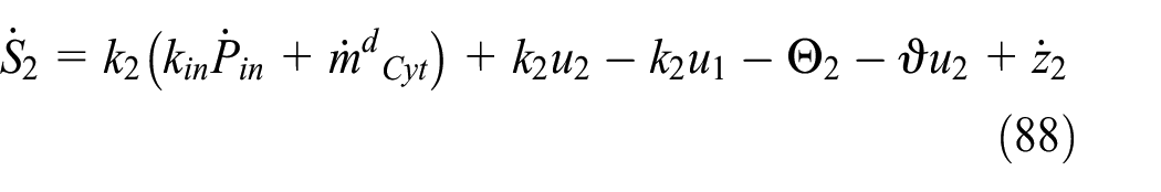
The controller structure

The Lyapunov function is used to get adaptation laws of unknown parameters
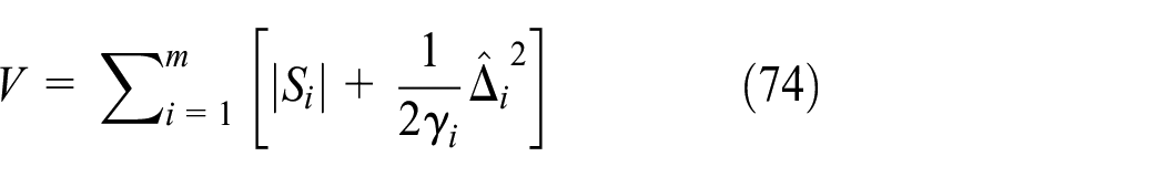
Where

Using equations (71) to (73) in (75).


If

Selecting

We have:

Lyapunov stability analysis in equation (80) provides the best-estimated values of faults and does not require any constraints on structured disturbances.
The non-linear model of the IC engine described earlier provides the most important properties of the proposed controller. From the previous equation (4) of air dynamics, we can write as:

Where


Where

Where

Where

The derivatives of the sliding variables after taking into account structured and unstructured uncertainties are:

Here,


Where

The control action is proposed in equation (67). To work out

For ideal plant:


To design a controller as HFTCS, we have combined the properties of both AFTCS and PFTCS.18,47 The working of the proposed HFTCS is shown in Figure 4.
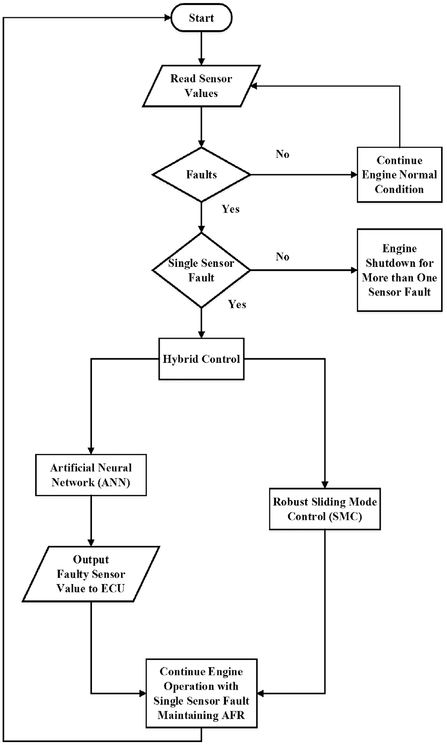
Proposed model of HFTCS.
Results and Discussions
For fault detection, isolation, and reconfiguration of controllers, FDI is implemented in the model with ANN. The FDI unit continuously tracks the sensor values for any fault. If the sensor value exceeds the specified limit, a fault is detected by threshold comparison. Once the fault has been observed, an estimated value of the observer model based on ANN is substituted for the fault value and is supplied to the ECU. The active part performs post-fault optimal performance for the active compensation by providing the estimated value of the faulty sensor by ANN observer using the other healthy sensors. Two ANNs have been introduced for throttle and MAP sensors. Since the engine is running at 300 r/min, this value has been supplied to the controller if a fault occurs in the speed sensor. The AFTCS portion is simulated with sensor faults one at a time and the effects on the AFR are observed at t = 5 s due to the internal warm-up delay of the engine, as shown in Figure 5. Results from Figure 5 show that the AFR is constantly degraded to 11.7 with every single sensor fault on the AFTCS portion alone.

Performance of AFTCS.
The passive part of the system consists of robust SMC. It provides a very quick response against fault, and after a very minor glitch in the output, the system maintains its steady state. Since the AFR decreases to 11.7 in the AFTCS part, the SMC controller with a fuel actuator is designed to keep it to 14.6 in faulty conditions.
In each of the four sensors, the faults are inserted at t = 0 s, and the results on the AFR are detected at t = 5 s due to internal warm-up times of 5 s in the original model. Figure 6 shows the results achieved for each sensor without noise in the sensors. The output response of the proposed PFTCS for faults in each sensor is demonstrated in Figure 6. In the existing model, AFR is affected by faults in each sensor and decreases to 11.7, that is, degradation in the performance in faulty conditions. However, the proposed PFTCS maintains AFR to 14.6 in normal as well as faulty conditions.

Performance of PFTCS.
These results show that the proposed PFTCS is robust to single-sensor faults.
The performance of the overall HFTCS for the four sensors is shown in Figure 7 in normal and faulty conditions. The system maintains an AFR of 14.6 in faulty situations, according to the results. The proposed HFTCS is resistant to sensor faults, preserving its performance and thereby avoiding AFR degradation. The results represent that after a very minor glitch, the system maintains its steady state with the help of a robust SMC controller. Table 4 illustrates the robustness of the proposed HFTCS with ANN and SMC without noisy conditions of sensors.

Performance of HFTCS without noise.
Performance of Proposed HFTCS without noise introduced.

After confirming adequate efficiency in noise-free operation, the system response is tested by integrating noise into sensor measurements. Table 5 shows the noise parameters introduced in the sensors. Greater noise is incorporated for throttle and speed sensor measurements due to high sensor values. Due to the very limited range, smaller noise is added in sensors EGO and MAP. In Figure 8, the effects of AFR are illustrated in normal and faulty conditions. The results demonstrated that after very minor sparks in the output, the system achieves the set point even under faulty conditions. The AFR remains stable with small misfires and the system continues to operate successfully in the noisy conditions of sensors. The performance of the proposed HFTCS with noise introduced is shown in Table 6.
Parameters of noise for sensors.


Performance of HFTCS in noisy conditions.
Performance of Proposed HFTCS with noise introduced.

The output response in Figure 8 is dominated by the PFTCS that is running in parallel with AFTCS. The active part performs post-fault optimal performance for the active compensation by providing the estimated value of the faulty sensor by ANN observer using the other healthy sensors. Since both controllers work in parallel, the active compensation effect does not become much evident due to the dominance of the passive controller. However, it becomes very much evident in only active FTCS as shown in Figure 5.
Comparison with the existing works
In this section, a comparison of the proposed HFTCS with the existing models is discussed. We have designed an HFTCS with dedicated non-linear controllers known as ANN and SMC. The previous work has not used the ANN and SMC together for HFTCS design for the AFR system of the IC Engine. In the proposed system, SMC will form the passive part to react instantly to faults while ANN will optimize post-fault performance with active compensation. Moreover, Lyapunov stability analysis was performed to make sure that the system remains stable in both normal and faulty conditions. The estimated values of the throttle and MAP sensors, as well as the accompanying mean square errors (MSE), are shown in Shahbaz and Amin. 4 ANN approach can cover the complete nonlinear range of the MAP sensor, which is also less computationally expensive than lookup tables and hence preferred. Due to its valuable functionalities of learning, self-organization, and non-linear modeling capabilities, the ANN technique is currently becoming a preferred strategy in fault diagnostics.
In Amin and Mahmood-ul-Hasan, 14 the HFTCS was proposed with Kalman Filters in the active part and a high-gain PI controller in the passive part. This algorithm was limited to the linear range of the highly nonlinear sensors of the AFR control system. In Su et al., 15 the HFTCS was proposed for the sensors of the distillation column without using any intelligent control or data-driven technique. In Wang et al., 16 the HFTCS was proposed for the uncertain networked control systems under a discrete event-triggered communication scheme that was not applied to the process plant. In Yang et al., 48 the authors focused on fault-tolerant control of Markov jump systems (MJS) with Itô stochastic process and output disturbances. A proportional-derivative sliding mode observer (SMO) and an observer-based controller are first devised and fabricated. In Yang et al., 49 the authors provided a fault-tolerant compensation control strategy for Markov jump systems against nonlinearity, simultaneous additive, and multiplicative actuator failures. A fuzzy logic system (FLS) was used to estimate the nonlinear functions and by using the adaptive backstepping approach, an FLS-based adaptive fault-tolerant compensation controller is developed. The proposed methods worked very well for the stochastic disturbances and simultaneous additive and multiplicative type faults in the actuators. However, the stochastic delays and actuator faults were not studied in this paper.
The proposed HFTCS has PFTCS for AFR control, which is based on SMC, and AFTCS based on ANN. With the use of a fuel throttle actuator, the proposed HFTCS will compensate for the AFR degradation by the AFR control. In the proposed system, SMC will form the passive part to react instantly to faults while ANN will optimize post-fault performance with active compensation as shown in Figure 5. The previous works mentioned in the literature have not yet utilized any intelligent control technique like ANN for the AFTCS and regular sliding mode control for the PFTCS, as proposed in this paper. The proposed model was found to be robust to faults in the normal and noisy conditions of the sensors. Therefore, the proposed HFTCS with ANN and SMC presents an optimum and reliable solution for AFR control in SI IC engines. Table 7 provides a comprehensive comparison of the suggested strategy with previously used strategies.

Conclusions
In this paper, a novel HFTCS was proposed for the AFR control of the IC engine based on the advanced non-linear controllers: ANN and SMC. With the use of a fuel throttle actuator, the proposed HFTCS was able to compensate for the AFR degradation with SMC that formed the passive part to react instantly to faults while ANN was able to optimize post-fault performance with active compensation. The Lyapunov stability analysis was also performed to make sure that the system remains stable in both normal and faulty conditions. The fault tolerance was checked with noisy measurements of sensors to examine the robustness of the proposed controller. The simulation results in the Matlab/Simulink environment show that the designed controller is robust to faults in normal and noisy measurements of the sensors and reliable. Furthermore, a comparison with the existing works was also carried out to demonstrate its superior performance.
Future works may include the design of HFTCS with modern control techniques known as Deep learning with Adaptive SMC, Neuro-Fuzzy SMC, and Integral SMC by testing at higher speeds considering load variations. Partial faults may also be considered with these techniques with experimental verification using the hardware-in-the-loop technique. Another direction is to consider the stochastic delays for the fault-tolerant AFR controller design.
Footnotes
Acknowledgements
The authors would like to thank colleagues for suggestions to improve paper quality.
Handling Editor: Chenhui Liang
Declaration of conflicting interests
The author(s) declared no potential conflicts of interest with respect to the research, authorship, and/or publication of this article.
Funding
The author(s) received no financial support for the research, authorship, and/or publication of this article.