
Abstract
A comprehensive computer model of the cerebral circulation, based on both hydrodynamics and electrical network analysis, was used to investigate the influences of arteriovenous malformations (AVM) on regional cerebral hemodynamics. The basic model contained 114 normal compartments: 55 arteries, 37 veins, 20 microvessel groups (MVG), one compartment representing systemic and extracranial vascular resistance, and one representing the heart. Each microvessel group, which represented the arteriolar bed, consisted of 5000 microvessels. Cerebral blood flow autoregulation was simulated by a formula that determined the resistance and therefore the flow rate of the microvessel groups (arterioles) as a function of perfusion pressure. Elasticity was introduced to describe the compliance of each vessel. Flow rate was made a controlling factor for the positive regulation of the diameters of conductance vessels by calculation of shear stress on the vessel wall (vessel dilation). Models containing an AVM were constructed by adding an AVM compartment and its feeding arteries and draining veins. In addition to the basic model, AVM models were simulated with and without autoregulation and flow-induced conductance vessel dilation to evaluate the contributions of these factors on cerebral hemodynamics. Results for the model with vessel dilation were more similar to clinical observations than those without vessel dilation. Even in the presence of total vasoparalysis of the arteriolar bed equivalent, obliteration of a large (1000 mL/min) shunt flow AVM resulted in a near-field CBF increase from a baseline of 21 to a post-occlusion value of no more than 74 mL/100 g/min, casting doubt on a purely hemodynamic basis for severe hyperemia after treatment. The results of the simulations suggest that our model may be a useful tool to study hemodynamic problems of the cerebral circulation.
Keywords
The hemodynamic effects of shunt flow through an arteriovenous malformation (AVM) on surrounding brain are incompletely understood and controversial. Interest is driven not only by a desire to clarify mechanisms of cerebrovascular regulation in health and disease, but also because altered cerebral hemodynamics have been implicated in the pathogenesis of pretreatment neurologic deficits and posttreatment complications. A conceptually attractive but unproven paradigm prevails to explain instances of pretreatment deficits, attributed to cerebral “steal” (Mast et al., 1994; Wade and Hachinski, 1987), and certain catastrophic posttreatment complications of brain swelling and intracranial hemorrhage, termed circulatory breakthrough (Nornes and Grip, 1980; Nornes et al., 1979) and normal perfusion pressure breakthrough (Spetzler et al., 1978). This paradigm is based largely on the observation that in some patients high-feeding artery flow reduces perfusion pressure in neighboring vascular territories (Barnett et al., 1987; Duckwiler et al., 1990; Jungreis et al., 1989; Kader et al., 1994; Miyasaka et al., 1993; Spetzler et al., 1992; Spetzler et al., 1987; Young et al., 1994a; Young et al., 1994b). Reduction in perfusion pressure may place these vascular territories at or below the lower limit of auto-regulation by a combination of arterial hypotension and venous hypertension, which may account for the occurrence of focal neurologic deficits. The evidence for such a pathomechanism is largely indirect and speculative (Mast et al., 1994; Wade and Hachinski, 1987). Chronic arteriolar vasodilation may result in “vasomotor paralysis,” both at sites near and distant from the AVM. Experimental evidence, however, for the pathophysiologic link between pretreatment hypotension and posttreatment hyperemia and subsequent swelling and hemorrhage is lacking (Young et al., 1996).
These perceptions of pathophysiologic mechanisms greatly influence both the interpretation of clinical phenomena and treatment choices. For example, one of the primary reasons for the current approach to staged treatment of AVM (either by embolization or staged surgery) is to prevent complications resulting from too rapid a “redistribution” of blood flow after shunt obliteration (Spetzler et al., 1987).
Although we and others have investigated relevant phenomena both in animal and clinical studies (Kader and Young, 1997; Brown and Spetzler, 1996), there are many questions that arise during interpretation of physiologic measurements (Lo, 1993), which can be addressed by a computer simulation of the pathophysiologic state. For example, if the high shunt flow induces cerebral arterial hypotension, what should be the extent and distribution of the pressure reductions9 If posttreatment hyperemia is a result of chronic cerebral hypotension, what is the extent and distribution-from a purely hemodynamic standpoint-of CBF changes after shunt obliteration? There have been several attempts to model the hemodynarnic consequences of cerebral shunt flow (Hademenos et al., 1996; Lo et al., 1991; Nagasawa et al., 1996; Nagasawa et al., 1993; Ornstein et al., 1994). This study was undertaken to improve on existing work in the area and to extend a model of the cerebral circulation so that it would be rigorous enough to eventually apply to the study of other cerebrovascular disorders.
METHODS
Structure
The structure of the basic model is a blood vessel network (Fig. 1). The element used to construct the model is a group of identical vessels or, as termed by other investigators (Hademenos et al., 1996; Lo et al., 1991; Nagasawa et al., 1996), a compartment. Each compartment has a unique number that is indicated in Tables 1 and 2 and is indicated in the text with the compartment number in boldface, followed by the beginning and ending node in brackets (e.g.,
Geometric and structural parameters of the compartments and vessels shown in Fig. 1
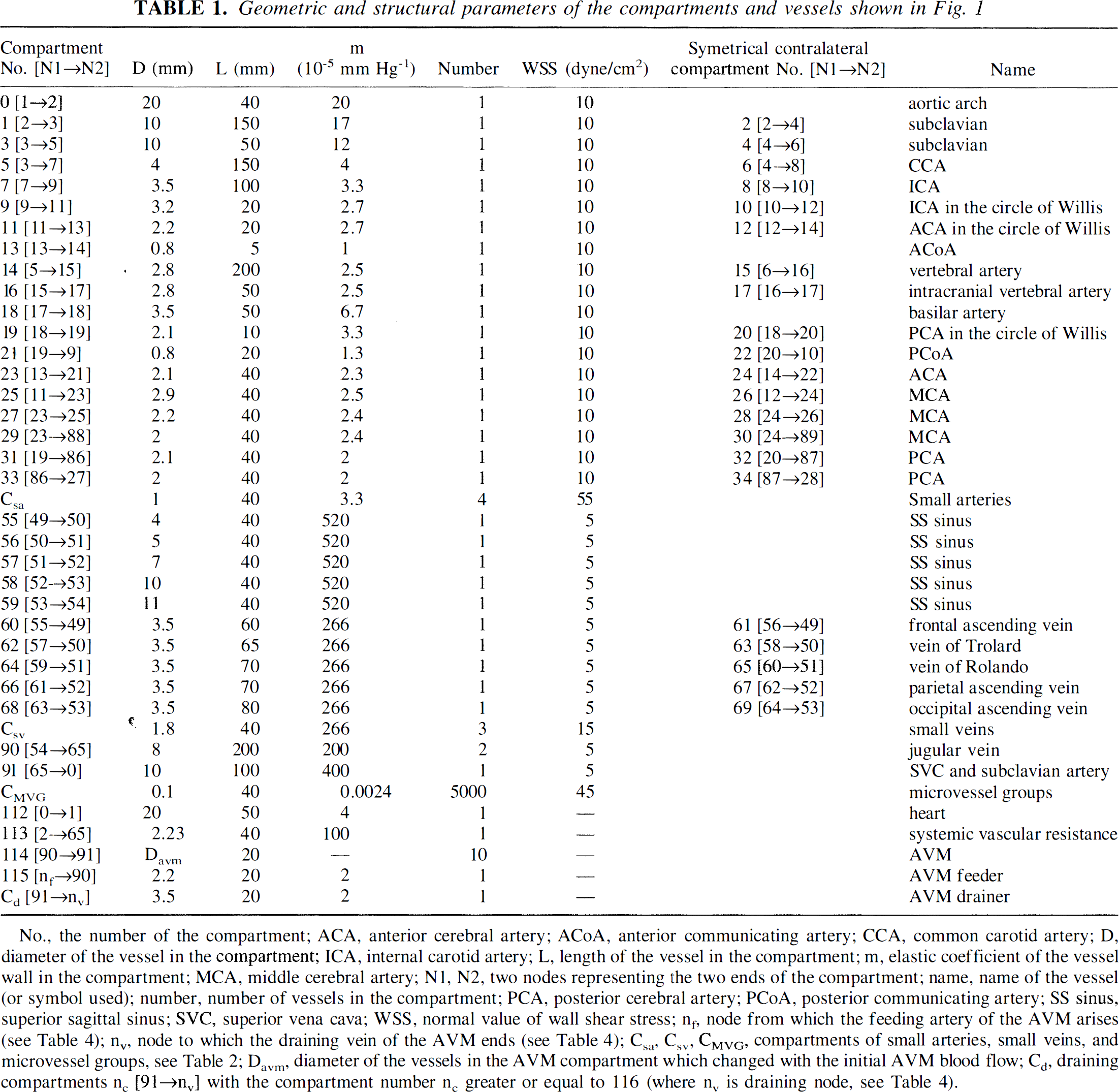
No., the number of the compartment; ACA, anterior cerebral artery; ACoA, anterior communicating artery; CCA, common carotid artery; D, diameter of the vessel in the compartment; ICA, internal carotid artery; L, length of the vessel in the compartment; m, elastic coefficient of the vessel wall in the compartment; MCA, middle cerebral artery; N1, N2, two nodes representing the two ends of the compartment; name, name of the vessel (or symbol used); number, number of vessels in the compartment; PCA, posterior cerebral artery; PCoA, posterior communicating artery; SS sinus, superior sagittal sinus; SVC, superior vena cava; WSS, normal value of wall shear stress; n1, node from which the feeding artery of the AVM arises (see Table 4); nv, node to which the draining vein of the AVM ends (see Table 4); Csa, Csv, VMVG, compartments of small arteries, small veins, and microvessel groups, see Table 2; Davm, diameter of the vessels in the AVM compartment which changed with the initial AVM blood flow; Cd, draining compartments nc [91→nv] with the compartment number nc greater or equal to 116 (where nv is draining node, see Table 4).
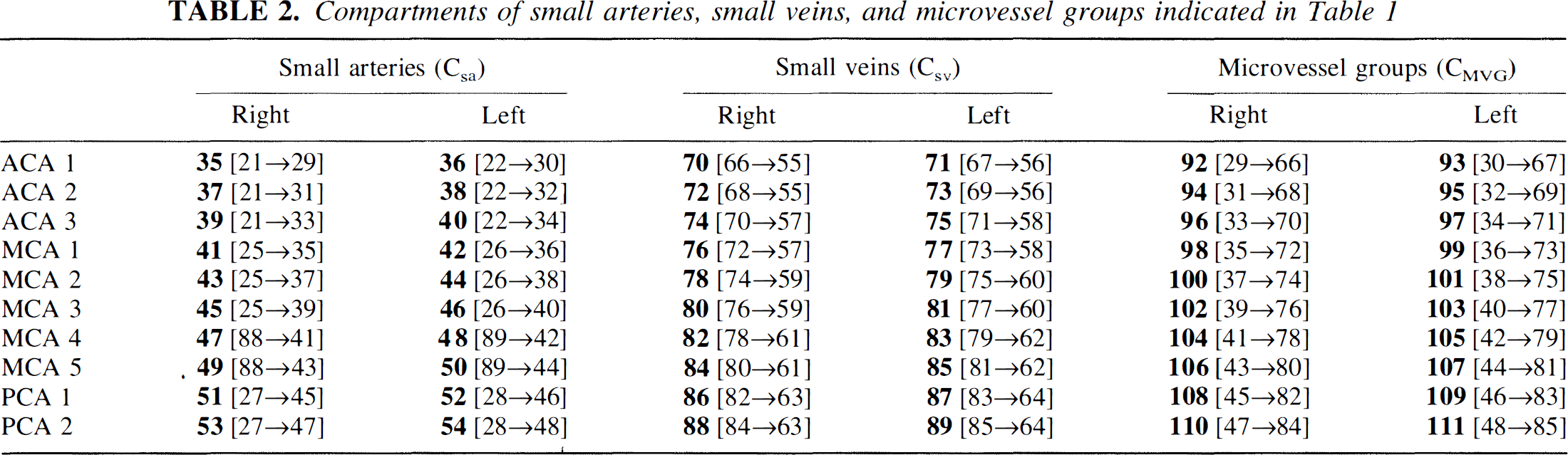
Compartments of small arteries, small veins, and microvessel groups indicated in Table 1
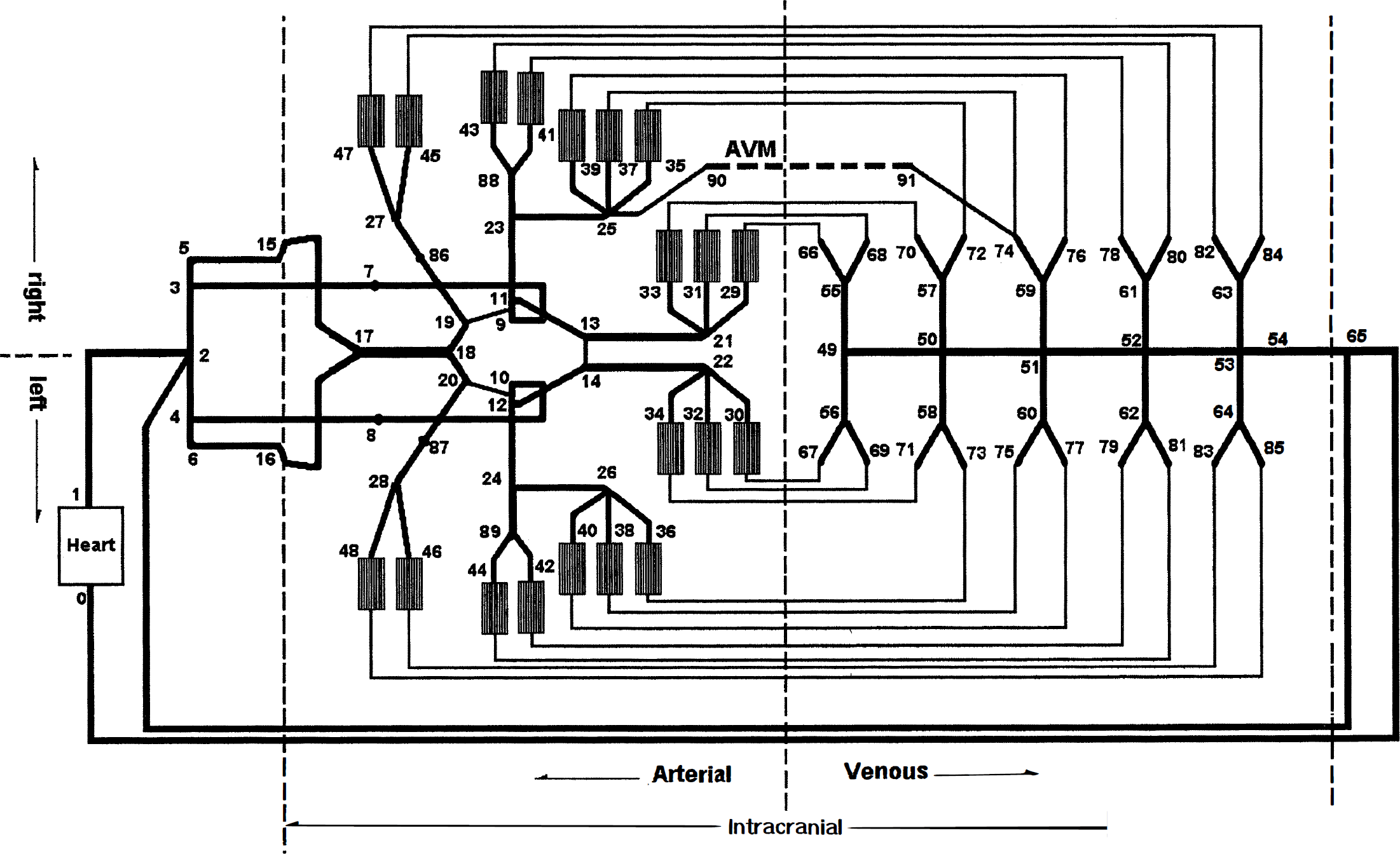
Schematic diagram of the model of intracranial blood vessel network. A thicker line represents a compartment that contains several identical vessels in parallel with each other. The numbers indicate the nodes. Between the arteries and the veins are 20 microvessel groups (MVG), each of which consists of 5000 microvessels. A thinner line between a MVG and a vein does not represent a compartment but indicates a connection between these two compartments. A middle cerebral artery (MCA) arteriovenous malformation (AVM) used in several of the simulations (see simulations 5 and 6 in Table 4) described in Methods also is shown. It connected nodes 90 to 91.
The model is structurally similar to the human cerebral circulation. The geometric and structural parameters of the vessel network of this model, such as radius, length, elastic coefficient of a blood vessel, and the number of vessels in the compartment as well as the position of its two ends within the model, are listed in Tables 1 and Table 2. Most of the parameters were taken from experimental or clinical observations (Hademenos et al., 1996; Huber, 1982; Kretschmann and Weinrich, 1986; Manchola et al., 1993; McDonald, 1974), whereas others were modified to compensate for the loss of resistance caused by approximating the curved blood vessels as straight.
The compartments included in the model can be separated into four groups: (1) those proximal to the circle of Willis, which contains the systemic vascular resistance (equivalent resistance of all systemic and extracranial vessels), (2) those within the circle of Willis and its major branches, (3) compartments that represent both arteriolar vessels and tissue (see later), and (4) intracranial veins. The intracranial compartments can be separated by their locations into right and left hemispheres.
To simulate the arteriolar resistance beds and brain tissue, we introduced microvessel groups (MVG) as special compartments. The model contains 20 MVG, each of them consisting of 5000 parallel small vessels, which are 0.1 mm in diameter, about twice as large as arterioles and about one third in number, as might be expected in the true circulation.* Each MVG is indicated as shown in Table 2. In addition to the nomenclature described earlier to name compartments, each MVG also has a name indicated in Table 2. For example, compartment
As shown in Fig. 1, 6 of the 20 MVG are perfused by the anterior cerebral artery (ACA), 10 are perfused by the middle cerebral artery (MCA), and the remaining 4 are perfused by the posterior cerebral artery (PCA). They are symmetrically distributed in left and right hemispheres. The posterior fossa and subcortical structures were not considered in the model. Assuming a brain weight of 1500 g, each MVG represents a brain tissue weight of 75 g. When we introduce AVM shunts into the model, we use the term near-field to denote one or more MVG immediately adjacent to the shunt compartment.
Mathematical and computational approach
Vessel branching.
For Newtonian fluids, the vessel radii should be related as (Murray's law)
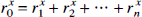
where ro is the radius of the parent vessel, rj(j = 1,2, …, n) are the radii of the daughter vessels, and x (the junction exponent) has a value of 3.00 (LaBarbera, 1995).
The frequency distribution of exponents for junctions of this model is close to the observation results (LaBarbera, 1995).
Hemodynamic properties of a single vessel.
It is well accepted that Poiseuille's formula is a sufficient approximation of single-vessel hemodynamics (Hademenos et al., 1996):

where Q is the flow rate through the vessel, ΔP the pressure drop across the vessel, r the inner radius, L the length, and η the blood viscosity (η = 3.5 centipoise).
If the internal pressure of the vessel is P, the relation between r and P can be approximated as
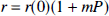
where r(0) is the vessel radius at P = 0, m is the elastic coefficient of the vessel (Ornstein et al., 1994). To estimate m using the essential parameters of the vessel, the following formula was used (Hademenos and Massoud, 1996):
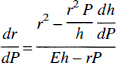
where E is the elastic modulus and h is the thickness. Substituting Eq. 3 into Eq. 4 and assuming that P is small enough to r approximate r(0), and that the terms containing P in Eq. 4 are negligible, the following is obtained: r(0)m = r2(0)/Eh or m = r(0)/Eh.
For the inclusion of autoregulation, the precapillary arterioles (embedded in the MVG) are assumed to regulate flow as a function of the mean perfusion pressure (pressure drop across the MVG).
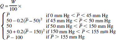
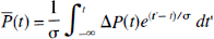
Here W is the weight of tissue perfused by one MVG and P} is the mean perfusion pressure averaged over a recent short period of time, defined as
where σ is a time constant. Function (6) is illustrated in Fig. 2 for σ = 2 seconds. With perfusion pressure between 50 and 150 mm Hg, flow is regulated to 50 mL/100 g/min. In the normal brain model, maximal vasodilation occurred at a mean arterial pressure of 45 mm Hg, and maximal vasoconstriction occurred at a pressure of 155 mm Hg. Thus, beyond these boundary conditions, CBF is proportional to perfusion pressure, like the flow through a rigid tube.
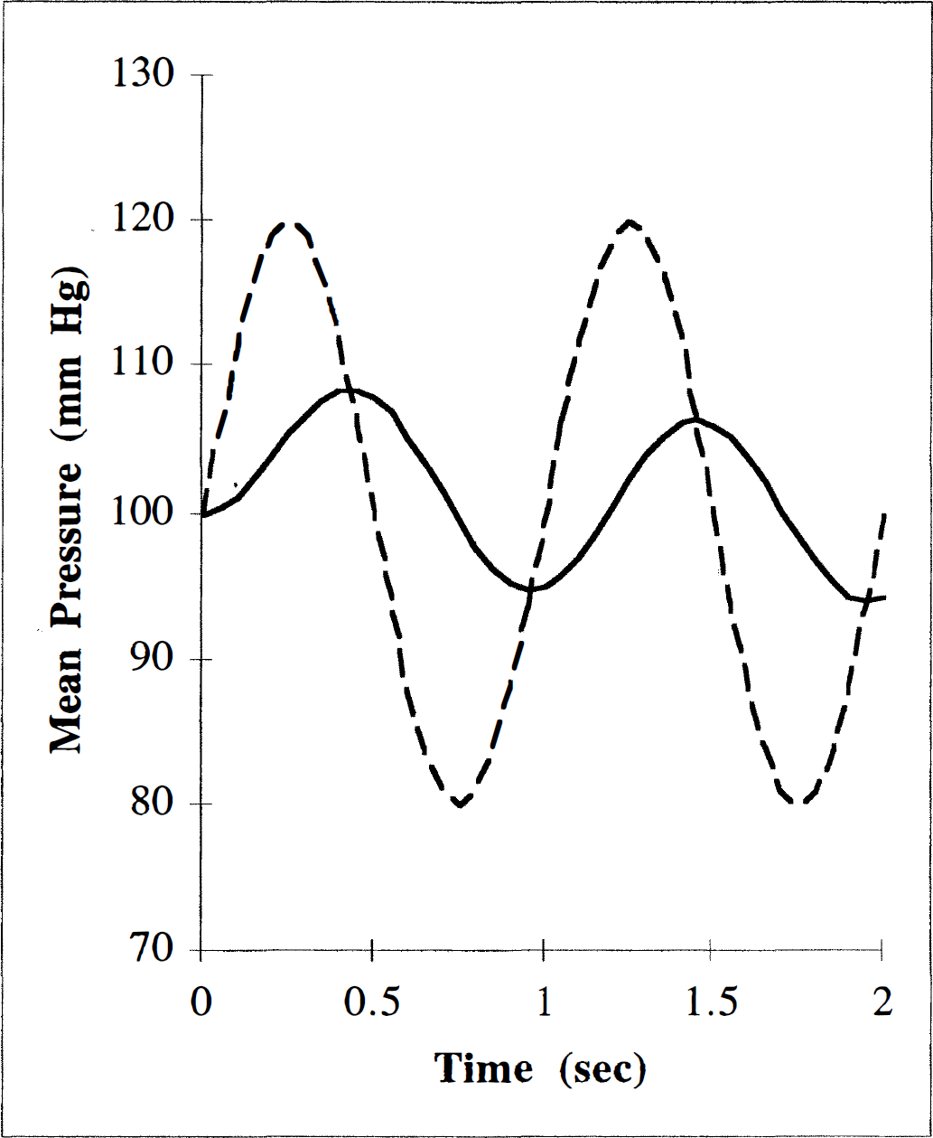
Illustration of mean perfusion pressure. The value of CBF depends on the mean perfusion pressure, which is defined in Eq. 6. The relation between the perfusion pressure ΔP(t) (dashed line) and its exponentially weighted running average defined by Eq. 6, P}(t) (solid line) are illustrated for time constant σ = 2 seconds.
Cerebral hemodynamics.
The entire intracranial cerebral tissue and its perfusing microvessels were divided into 20 identical segments or MVG, each of which is perfused by three small conductance arteries.
Using Poiseuille's law, the wall shear stress can be expressed in terms of the volumetric flow rate (Hademenos and Massoud, 1996)

It is observed clinically that a conductance blood vessel dilates if there is additional blood flow through the vessel. Although the mechanisms of vessel dilation remain unclear, shear stress on the vessel wall is one possible effector of dilation (Bevan and Laher, 1991; LaBarbera, 1995). In this model, when the mean shear stress is greater than 10 times normal, the vessel dilates to adjust shear stress until it is equal to 10 times the normal value. The normal value of shear stress for each vessel is listed in Table 1 (Lipowsky, 1995).
In our model, consisting of NC compartments, the jth compartment contains nj identical vessels, which have a uniform radius rj(0) at P = 0, and length Lj. Two or more compartments meet at a junction called a node. Each node has a unique number that is given in Fig. 1 and indicated in the text in italics (e.g., node 23). Nn is used to represent the total number of nodes of the model. According to Eq. 2, the flow through compartment j is
where rj is the mean radius of vessel j, and Pj,in and Pj,out are the pressures at the two ends of vessel j, nj is the number of vessels in compartment j. If k and k' are the two ends of compartment j,Eq. 8 can be rewritten as
where Qkk, is the flow rate from node k to k' and Qkk' = -Qkk'. According to the law of conservation of mass, a system of Nn node equations may be written for the sum of the blood flowing into node, k, representing the blood imagined to accumulate within these nodes.
where k' is the compartment entering or leaving node k, Δt is a small time interval, and Vk is the effective volume of node k.
In our model, each vessel serves as a bridge between two nodes. The volume of each vessel is assumed to be completely filled with blood, with half of the volume being associated with each node so that
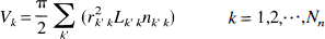
In Eqs. 10 and Eq. 11, k' is summed over all compartments connected to node k. Substituting Eqs. 3 and Eq. 11 into Eq. 10
where Δrk'k is the change of rk'k from t to t + Δt, and Δrk'k ≪ r k'k. In (equation 12) the approximation

is also used.
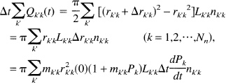
A series of distinct points in time are used to represent the change of time: t = {ti}, where ti < ti+l, (i = 0,1,2 …) and ti+l – tt = δt. δQ refers to the increase of flow Q during the time interval from ti to ti+l. Similarly, δP stands for the increase in pressure P. Substituting ti and ti + δt into Eq. 12, respectively, two equations are obtained. Subtracting these two equations, one gets
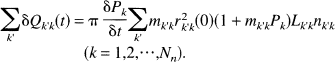
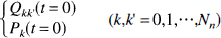
From Eq. 2, it can be seen that Qk'k (k,k' = 0,1, … Nn) depends on Pk, Pk, (k,k' = 0,1, … Nn). Starting with a proper set of initial conditions Eq. 14 can be solved:
As a special case, the heart not only has the common vascular properties of other vessels, but also is a driving pressure source. The systemic pressure and heart rate are changeable in the model, but normal baseline values of 120/80 mm Hg and 60 beats/min were assumed.
Creation of an arteriovenous malformation.
Right hemispheric AVM arising from either the ACA, MCA, or PCA was simulated. Three phenomena were investigated: (1) the influence of shear stress-induced vasodilation; (2) the effect of stepwise occlusion of the shunt; (3) the location of the AVM in the circulation. The initial AVM “nidus” (compartment
The influence of shear stress-induced vasodilation
An AVM of the MCA (Fig. 1) was simulated with stepwise 100-mL/min increments of shunt flow from 100 to 1200 mL/min to investigate the effect of conductance flow on diameter, blood flow velocity, and shear stress. These simulations were carried out with and without flow-induced vasodilation. The pressure distributions along the course of the ipsilateral MCA were simulated for a medium and a large MCA AVM.
The effect of stepwise occlusion of the AVM shunt
We studied the effects of AVM occlusion by reducing the number of vessels in the AVM compartment. We adapted the terminology of Nagasawa and associates (Nagasawa et al., 1996; Nagasawa et al., 1993) and present the results of gradual obliteration of shunt flow as percent occlusion of AVM. Obliteration of shunt flow was calculated as follows:

where 10 is the original number of the vessels in the AVM compartment, and x is the number of these vessels during the simulated occlusion.
The stepwise occlusion of AVM shunt flows were simulated for a medium (500 mL/min) and a large (1000 mL/min) AVM. The process of occlusion was designed as follows. The size of the feeding vessel was calculated during zero occlusion and was maintained at the calculated radius despite further occlusion. The CBF of MVG MCA2, compartment
Results were simulated with and without autoregulation (see later). Simulations also were performed eliminating autoregulation only in those MVG in which preocclusion perfusion pressure was lower than 50 mm Hg, which may have more clinical relevance.
The location of the AVM in the circulation
The simulations to estimate the effects of the location and the volume of the near-field tissue were conducted. A large AVM was placed in either ACA, MCA, or PCA. The near-field tissue was selected to be either one or three MVG for both ACA and MCA AVM, and either one or two MVG for PCA AVM. A large AVM arising from a more proximal level on the MCA tree was simulated with the selected near-field tissue of five MVG.
Computational approach
A computer program was written using C++ to simulate the model circulation. This program calculates the flow rate, flow velocity, diameter, wall shear stress for every vessel, and pressure for every node. This program has two “switches,” which can change the properties of the model. One switch is the autoregulation switch (+a/-a). If this switch is turned on (+a), the arterioles actively autoregulate the blood flow; otherwise (-a), they function as passive vessels. Another switch is the dilation switch (+d/-d). If this switch is turned on (+d), the conductance vessel dilates when the wall shear stress of the vessel exceeds its given critical value; otherwise (-d), the vessel is insensitive to the shear stress (or blood flow).
RESULTS
The model circulations were simulated for both the basic (normal) model and models containing an AVM. Both switches (+a/-a) and (+d/-d) were used to change the properties of the model. The simulation also was conducted for AVM occlusion.
Comparison with normal circulation
The computed results of the basic model (without AVM) are listed and compared with observed normal values in Table 3. The differences in diameters (proximal ACA, MCA, and PCA) and CBF between the simulated results and the observed ones (Hassler, 1986b; Lipowsky, 1995; Manchola et al., 1993; Sakai et al., 1985) are less than 4%, the difference in velocities is less than 18%. The cerebral blood volume for brain tissue is 2.1 mL/100 g. This value is smaller than experimental observations, which are in the range of 4 ∼ 5 mL/100 g (Lipowsky, 1995; Sakai et al., 1985). The model demonstrates a smaller cerebral blood volume because it does not include true capillary beds, which contain more blood than the arterioles (Table 3). The shear stress of the blood flow on the wall of the vessel is comparable with published data (Lipowsky, 1995) and is shown in Fig. 3. Except for large arteries, the calculated shear stress is close to previously reported results. For large arteries, we found shear stress to be 50 dyne/cm2, which is close to the value calculated from experimental observations and is discussed later (Fig. 4). The pressure distribution of the basic model was simulated and is discussed in the next section.
Comparison of the results with clinical observations
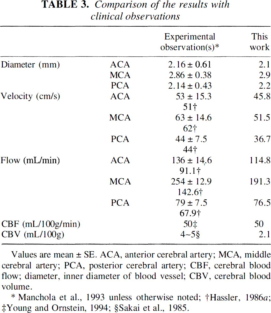
Values are mean ± SE. ACA, anterior cerebral artery; MCA, middle cerebral artery; PCA, posterior cerebral artery; CBF, cerebral blood flow; diameter, inner diameter of blood vessel; CBV, cerebral blood volume
Manchola et al., 1993 unless otherwise noted;
Hassler, 1986;a
Young and Ornstein, 1994;
Sakai et al., 1985.
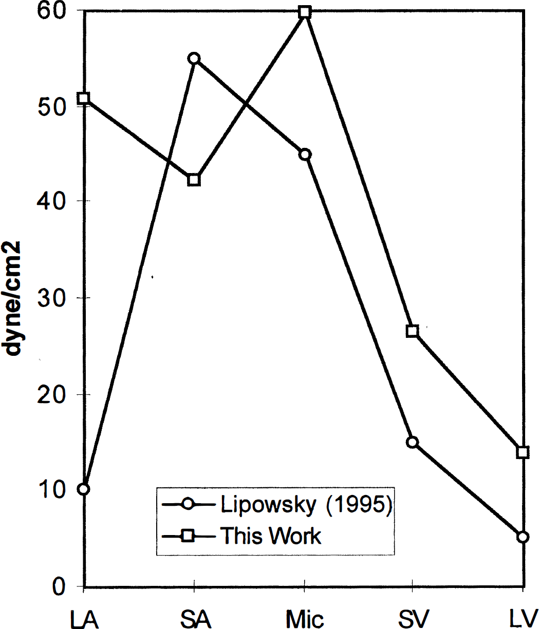
Shear stress on the wall of middle cerebral artery (MCA) and its branches as well as draining veins in the basic model. Data from our model (squares) are close to those from Lipowsky (circles), except for the large arteries (Lipowsky, 1995). For large arteries, the result of our model, 50 dyne/cm2, is close to the values calculated from the observations (Fig. 4) (Hassler, 1986b; Manchola et al., 1993; Nornes and Grip, 1980). LA: large MCA arteries; SA: small arteries; Mic: microvessels; SV: small veins; LV: large veins.
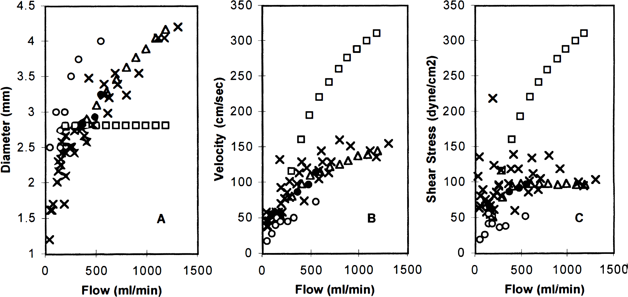
Effects of vessel dilation on the large middle cerebral artery (MCA) diameter
The influence of shear stress-induced vasodilation
The effects of vessel dilation are illustrated in Fig. 4. The computed diameter of a large MCA vessel (vessel 27 in Table 1), velocity of the blood flow through it, and the shear stress on its wall for the (+a+d) model are compared with those for the (+a-d) model and the observation results (Hassler, 1986b; Manchola et al., 1993; Nornes and Grip, 1980). The results of the (+a+d) model were more similar to experimental observations than those of the (+a-d) model; the error of the (+a-d) model became large if the AVM shunt flow was large. For example, in the (+a-d) model, if the flow of the AVM is 1200 mL/min, the error of the MCA diameter is 50%, the error of the MCA blood flow velocity is 100% and the error of the wall shear stress is 200%. However, in the (+a+d) model, these three errors are negligible. Thus, the vessel dilation function is necessary to simulate the dynamic response of a blood vessel network to a large AVM.
The pressure distributions along the course of the ipsilateral MCA are illustrated for a medium AVM and a large AVM in Fig. 5. For large arteries, such as the internal carotid and proximal MCA, the pressure remained approximately the same because the vessel dilation partially attenuated the additional pressure loss caused by the increased blood flow. For more distal arterial sites, approaching the level of the pial circulation, the pressure decreased more for the large AVM than for the medium one. The simulated pressures are compared with clinical observations (Fogarty-Mack et al., 1996a) in Fig. 6. The predicted values of our model for the medium AVM are close to the mean values of the experimental observations of Fogarty-Mack and coworkers.
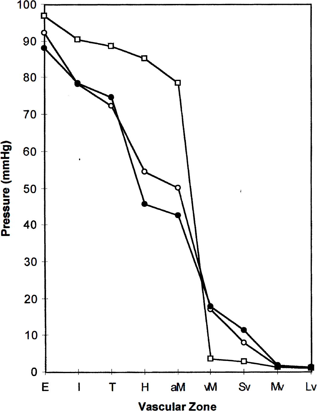
Pressure distributions of the ipsilateral middle cerebral artery (MCA) in the presence of either a medium arteriovenous malformation (AVM) (open circles) or a large AVM (closed circles) compared with that in the normal model (squares). The pressures at proximal conductance vessels decreased and the venous pressure increased in the presence of an AVM. E, extra-cranial: systemic pressure at level of coaxial catheter in extracranial vertebral artery or internal carotid artery (in this model, node 7); I, intracranial: supraclinoid internal carotid artery or basilar artery (in this model, node 11); T, transcranial Doppler insonation site: A1, M1, or P1 (in this model, node 23); H, halfway: arbitrarily “halfway” between T and the feeding artery (in this model, H, node 25; feeding artery, node 90 or zone F in Fig. 6); aM, arterial side of the microvessels (in this model, node 37); vM, venous side of the microvessels (in this model, node 74); Sv, small vein (in this model, node 59); Mv, medium vein (in this model, node 51); Lv, large vein (in this model, 53); E, I, T, H: vascular zones taken from Fogarty-Mack and associates (Fogarty-Mack et al., 1996a).
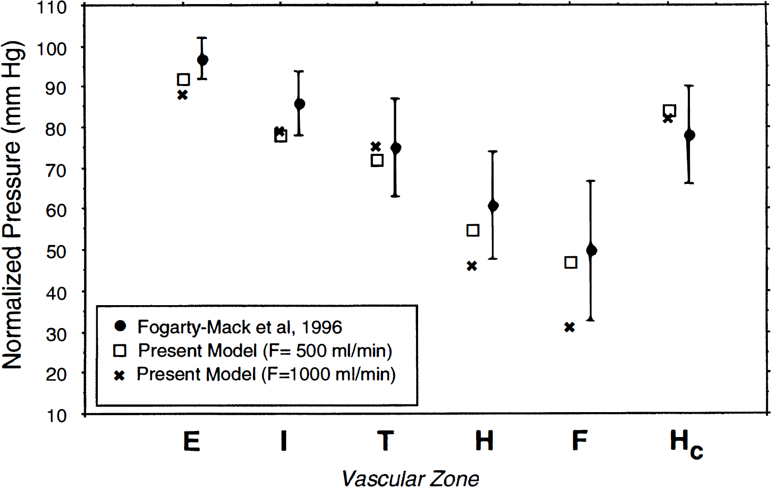
Normalized pressure ratios in zones E, I, T, H, F, and Hc compared with clinical observations. The predicted values of our model for the medium arteriovenous malformation (AVM) are close to the mean values of the experimental observations of Fogarty-Mack et al. (Fogarty-Mack et al., 1996b). E, extracranial: systemic pressure at level of coaxial catheter in extracranial vertebral artery or internal carotid artery (in this model, node 7); I, intracranial: supraclinoid internal carotid artery or basilar artery (in this model, node 11); T, transcranial Doppler insonation site: A1, M1, or P1 (in this model, node 23); H, halfway: arbitrarily “halfway” between T and the feeding artery (in this model, node 25); F, feeder (in this model, node 90); Hc, contralateral distal arterial pressure (in this model, node 26); E, I, T, H, F, and Hc: vascular zones taken from Fogarty-Mack and associates (Fogarty-Mack et al., 1996a).
The effect of stepwise occlusion of the AVM shunt
The CBF of MVG MCA2 adjacent to the AVM (near-field tissue compartment) perfused by ipsilateral MCA is plotted as a function of the percent occlusion of the AVM for both medium (A) and large (B) AVM in Fig. 7, corresponding to an AVM in the anatomic location shown in Fig. 1. Arterial and venous pressures are also indicated. This simulation assumed the presence of vessel dilation due to shear stress (+d). Both presence (+a) and absence (-a) of autoregulation are simulated and compared with each other. As the percent occlusion increased from 0 to 100%, the AVM flow decreased to zero from 500 mL/min for the medium AVM and from 1000 mL/min for the large AVM. For the model with autoregulation (+a), the perfusion pressures increased from 33 to 66 mm Hg for the medium AVM (Fig. 7A) and from 21 to 70 mm Hg for the large AVM (Fig. 7B). Before occlusion, the CBF in the near-field tissues compartment (MVG represented by compartment 100 [37→74] in Table 2) was 33 mL/100 g/min for the medium AVM and 21 mL/100 g/min for the large AVM. When the percent occlusion was larger than 70% for the medium AVM or larger than 90% for the large AVM, the CBF of the near-field tissue returned to a normal level (approximately 50 mL/100 g/min). The CBF in the model without autoregulation (-a) increased further with a percent occlusion of greater than 70% for the medium AVM and 90% for the large AVM. With complete occlusion, CBF increased to 66 mL/100 g/min for the medium AVM and 71 mL/100 g/min for the large AVM. For constructing Fig. 8, only regions where the preocclusion perfusion pressure was lower than 50 mm Hg lacked autoregulation.
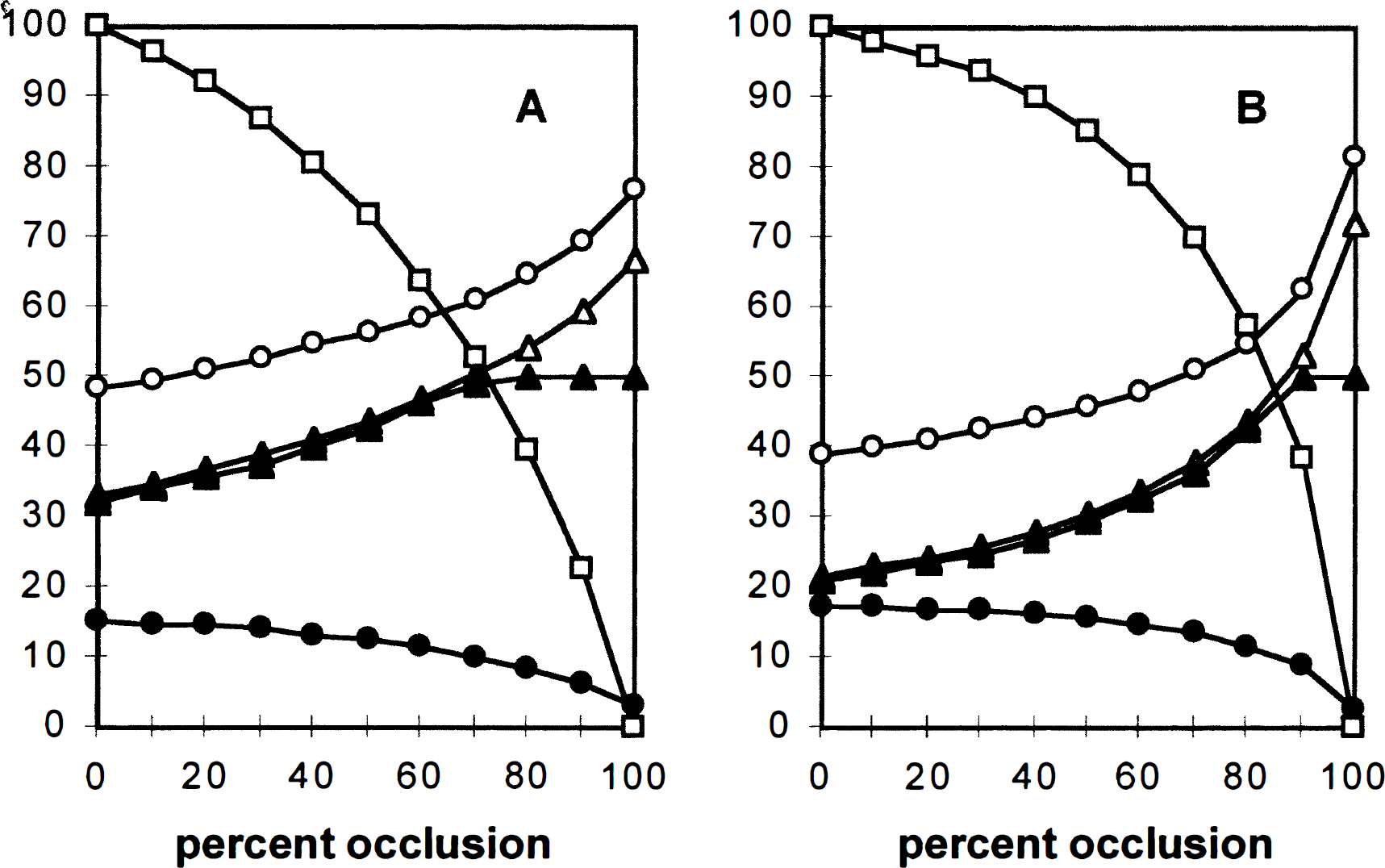
Effects of stepwise occlusion for medium
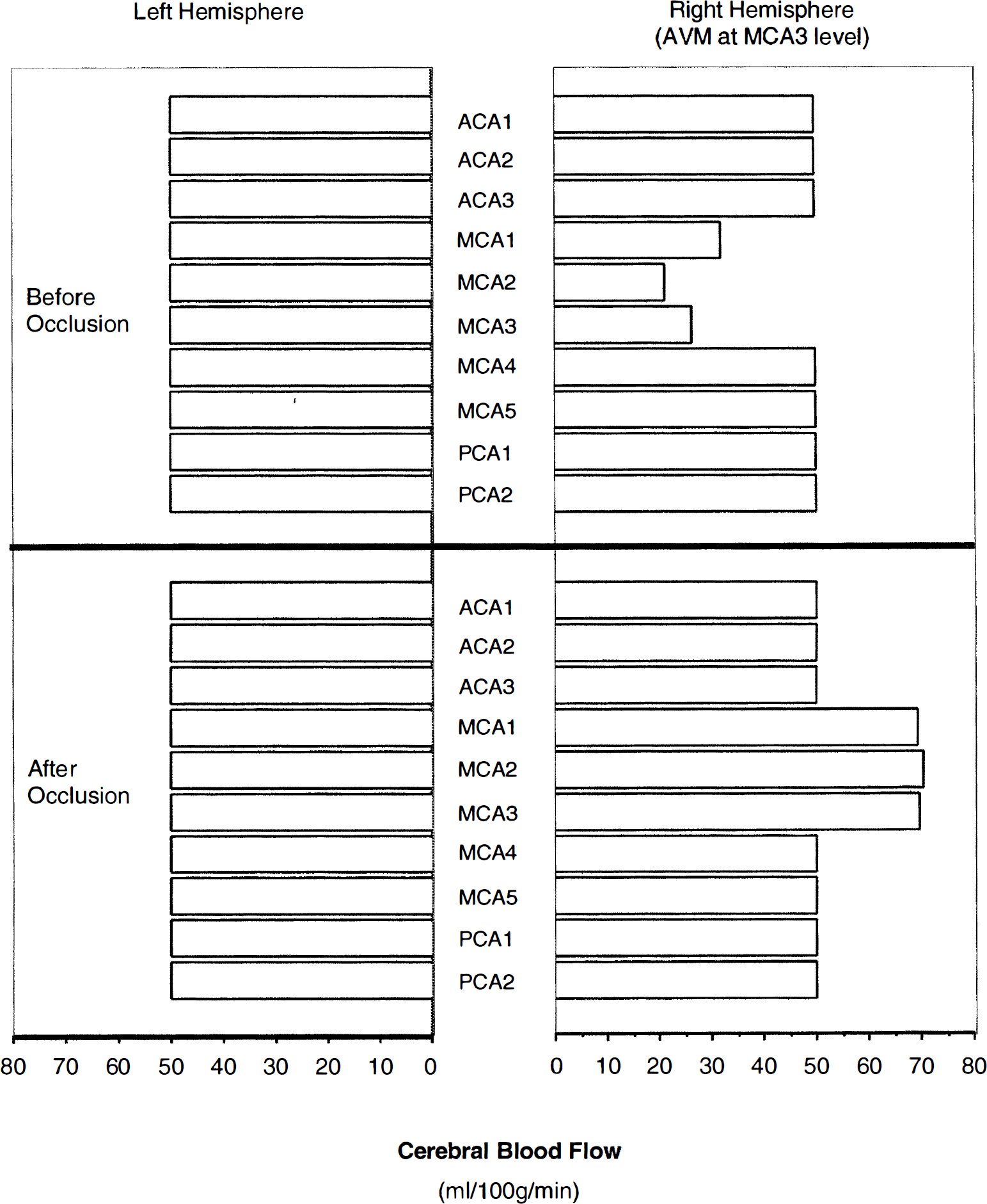
Regional CBF in the presence of a large middle cerebral artery (MCA) arteriovenous malformation (AVM) (located at the right hemisphere, corresponding to no. 5 in Table 4) compared with that after complete occlusion of the AVM. In the presence of the AVM, the CBF of ispilateral fields MCA1, MCA2, and MCA3 decreased from normal values of 50 mL/100 g/min to 32, 21, and 26 mL/100 g/min, respectively. In other ispilateral regions and the contralateral hemisphere, the CBF was normal. After occlusion, the CBF of ispilateral MCA1, MCA2, and MCA3 increased to approximately 70 mL/100 g/min because of the absence of autoregulation in these three regions, suggesting a limited potential for severe increases in CBF after shunt occlusion purely on a hemodynamic basis.
Because we introduced conductance vessel dilation in the simulation of the AVM, the dilation introduced for full shunt flow was maintained throughout the stepwise occlusion up to a nidus shunt of zero and is therefore not the same as in our model of the normal circulation.
The location of the AVM in the circulation
To estimate the influence of the location and the volume of the near-field tissue of AVM, 14 models were simulated by changing the location and the size of its near-field tissue compartment for both “with” and “without” autoregulation. Table 4 shows the summary of our simulation conditions and the computed CBF of the near-field tissue compartment (MVG adjacent to the AVM) both before and after occlusion of the AVM. From Table 4, it can be seen that the location of AVM and the volume of its near-field tissue made no significant difference in CBF. On average, CBF increased from 29 to 72 mL/100 g/min for a large AVM after AVM occlusion, assuming no autoregulation (Fig. 9). With autoregulation, CBF increased from 29 to 50 mL/100 g/min for a large AVM after AVM occlusion. Small AVM with initial flow of 200 mL/min also were simulated for each of the 14 conditions listed in Table 4; however, the changes in CBF were clinically insignificant and not presented.
Summary of the simulation conditions and the results of CBF for large AVM in differing locations
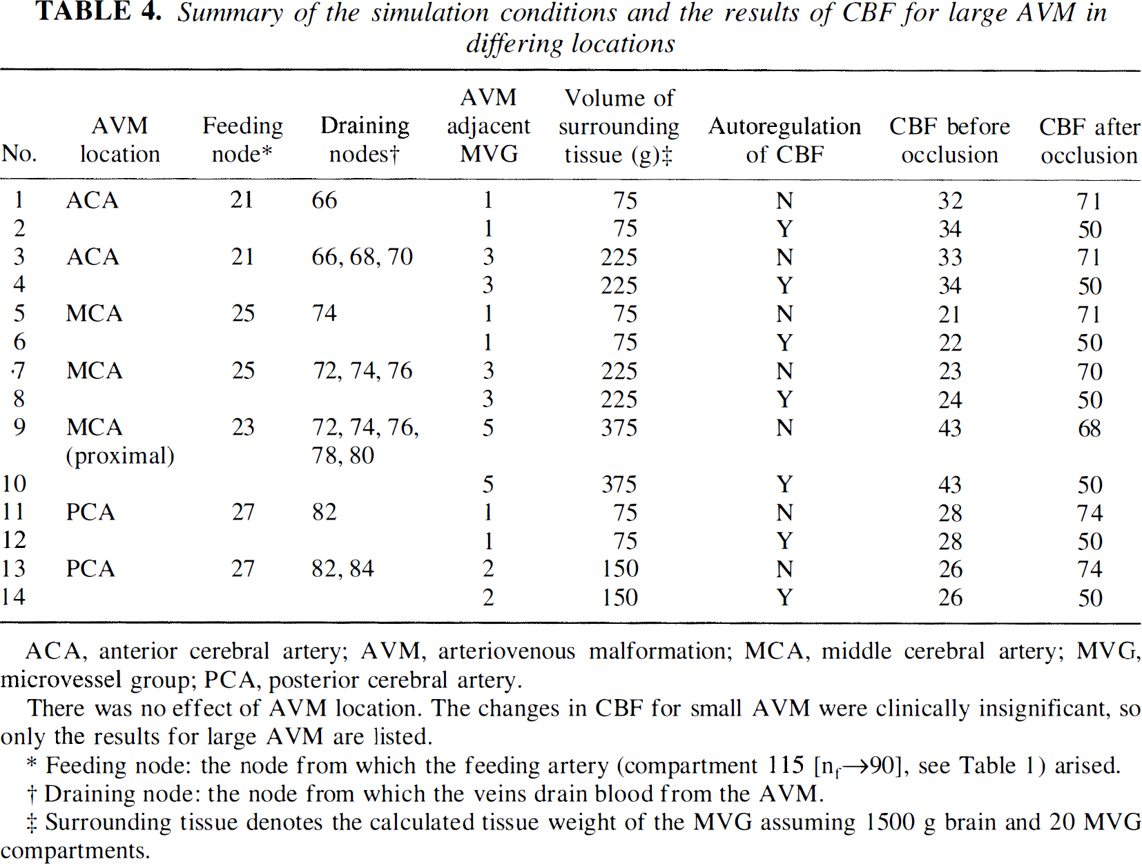
ACA, anterior cerebral artery; AVM, arteriovenous malformation; MCA, middle cerebral artery; MVG, microvessel group; PCA, posterior cerebral artery.
There was no effect of AVM location. The changes in CBF for small AVM were clinically insignificant, so only the results for large AVM are listed.
Feeding node: the node from which the feeding artery (compartment 115 [nf→90], see Table 1) arised.
Draining node: the node from which the veins drain blood the AVM.
Surrounding tissue denotes the calculated tissue weight of the MVG assuming 1500 g brain and 20 MVG compartments.
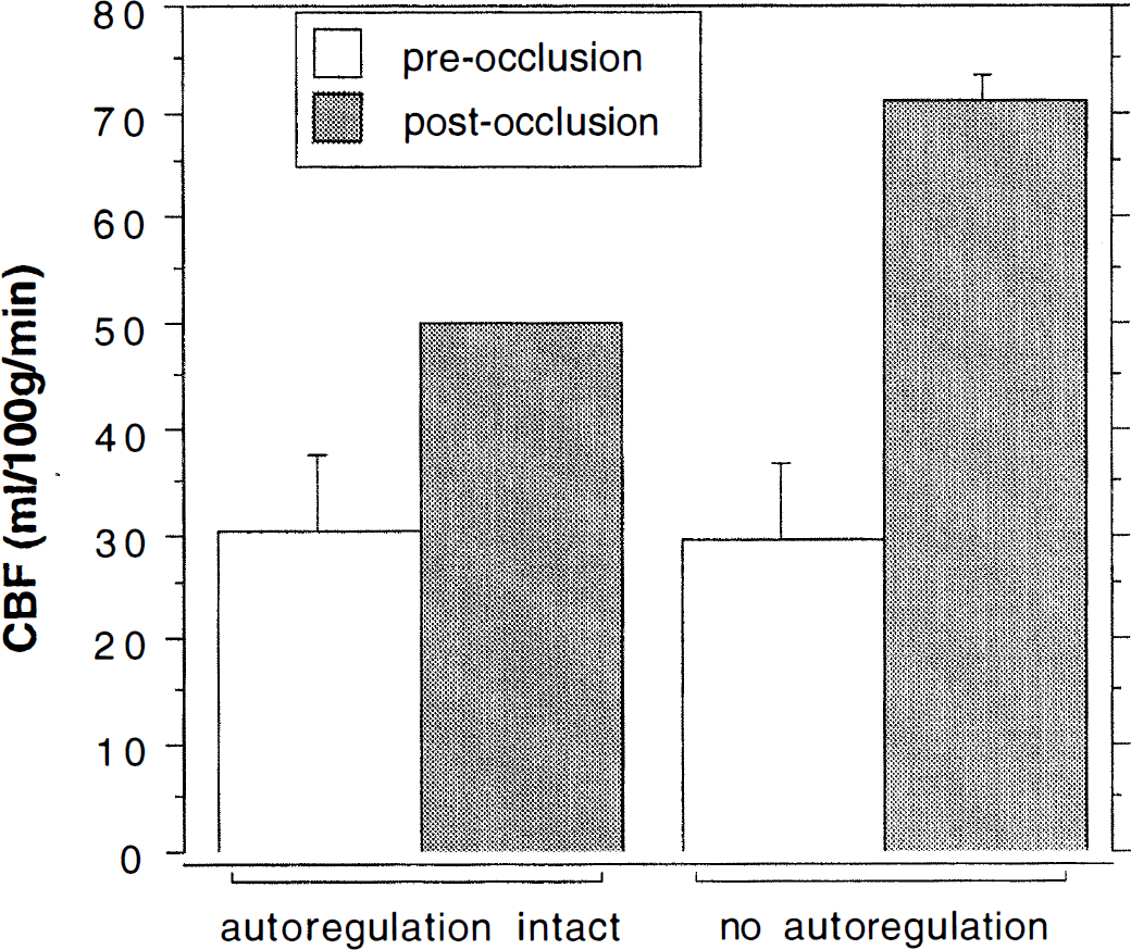
Illustration of the mean increase in CBF after arteriovenous malformation (AVM) obliteration in the various simulations of near-field regions with and without the presence of autoregulation that are detailed in Table 4.
The result simulated for a large AVM arising from more proximal level on the MCA tree also are listed in Table 4 (simulations 9 and 10). Placing the AVM in a more proximal location did not greatly affect the post-occlusion hemodynamic changes.
DISCUSSION
A comprehensive theoretical model of the cerebral circulation was constructed and simulated for both normal and abnormal circulations. The abnormal models included either a small-, medium-, or a large-sized AVM. Shear stress-induced vessel dilation was introduced in our model (to our knowledge, for the first time). The simulated results for most of the derived vascular parameters are close to clinical observations, which suggests that this model has the potential to be a useful tool for simulation of a wide variety of cerebrovascular perturbations. Notice that even in the presence of total vasoparalysis of the arteriolar bed equivalent, obliteration of a large shunt flow AVM resulted in a limited, near-field CBF of no higher than 74 mL/100 g/min, casting doubt on a purely hemodynamic basis for severe global or even hemispheric hyperemia after treatment.
In the construction of this model, previous studies and clinical observations were taken into consideration. A comparison of the characteristics of this model with other models is shown in Tables 5 and Table 6.
A comparison of several models of cerebral arteriovenous malformations
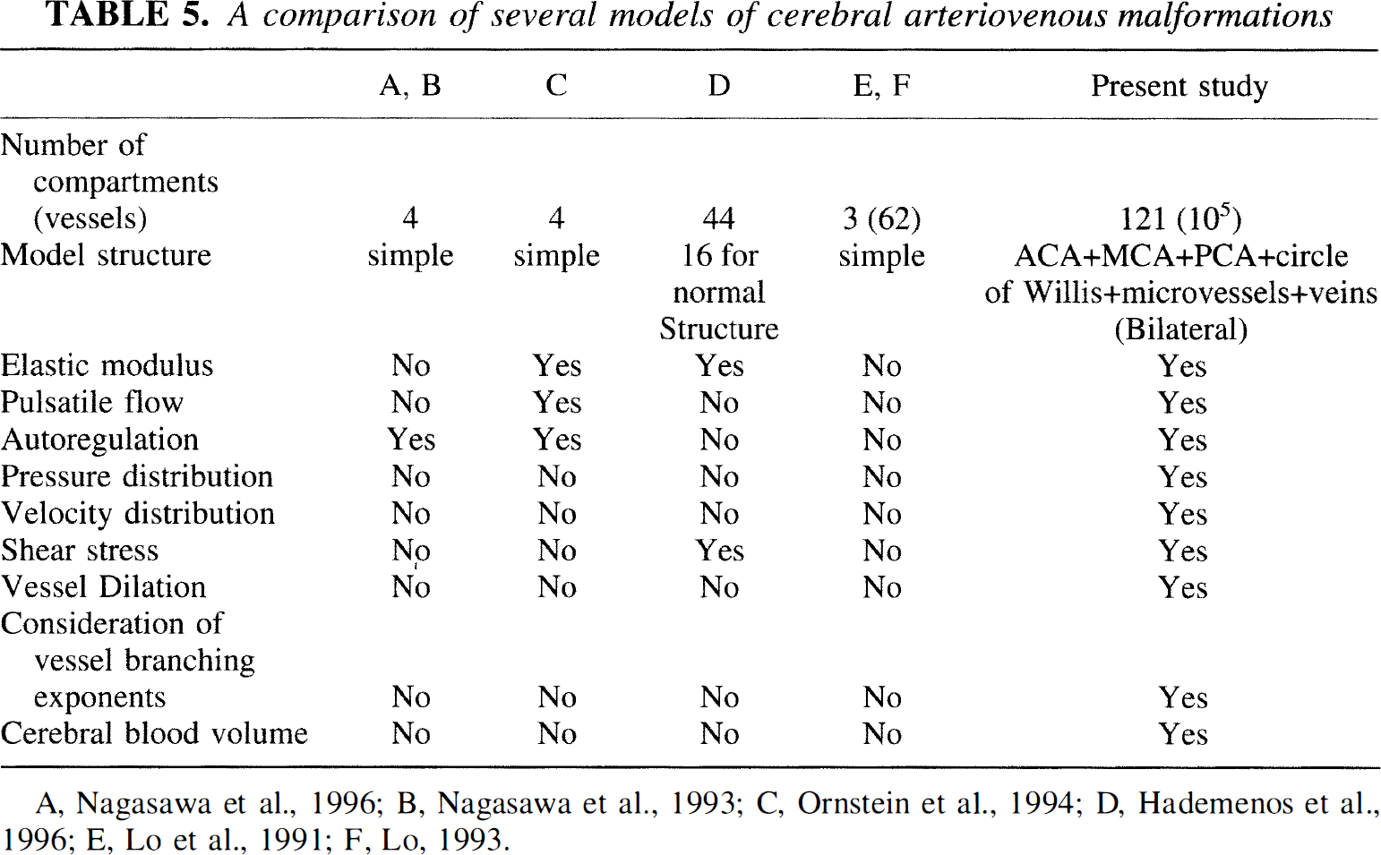
A, Nagasawa et al., 1996; B. Nagasawa et al., 1993; C, Ornstein et al., 1994; D, Hademenos et al., 1996; E, Lo et al., 1991; F, Lo, 1993.
Comparison of some intracranial vessels with previous work
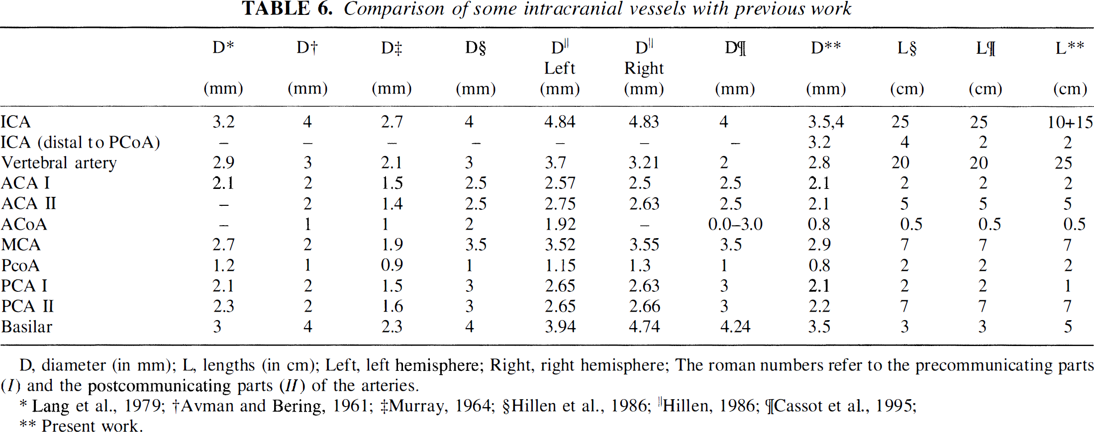
D, diameter (in mm); L, lengths (in cm); Left, left hemisphere; Right, right hemisphere; The roman numbers refer to the precommunicating parts (I) and the postcommunicating parts (II) of the arteries.
Lang et al., 1979;
Avman and Bering, 1961;
Murray, 1964;
Hillen et al., 1986;
Hillen, 1986;
Cassot et al., 1995;
Present work.
The number of vessels in a model is important. The model used by Lo and coworkers (Lo et al., 1991) has three compartments (vessels) to represent the AVM, each one consisting of several identical vessels, and has one normal vessel to represent the surrounding vasculature. Others (Nagasawa et al., 1996; Ornstein et al., 1994) used four vessels in their models, representing feeding artery, the supply to the surrounding brain, the AVM fistula, and the draining vein. The model used by another group (Hademenos et al., 1996) has 44 vessels, including a complex AVM network. However, the 16 vessels, which are used to build the supplying and surrounding structure of the AVM, seem to be insufficient because six electromotive force generators were necessary, in addition to the heart, to adjust the pressures (or flows) to normal values.
Our model consists of 114 normal compartments and several other compartments representing the AVM. To simulate the hydrodynamic properties of the microvessels, 20 of the 114 compartments are used to represent 20 MVG, each of which consists of 5000 identical microvessels. Because this model contains a greater hierarchy of vessels than any previous model, its hemodynamic properties are more similar to real intracranial circulation. In this model, we have included adjacent circulatory beds of the long circumferential (ACA, MCA, PCA) arteries. This results in a more accurate prediction of the effects of AVM shunt flow on tissue perfusion and pressure in neighboring territories. Moreover, in the future, it will enable modeling of AVM that are fed by multiple arteries, which is the usual clinical circumstance.
The structures of the previously reported models are relatively simple and differ from the real blood vessel network. Our model contains the essential segments of an intracranial blood circulation system and the necessary supplying vessels. It includes the heart, aortic arch, subclavian arteries, carotid arteries, vertebral arteries, basilar artery, the circle of Willis, ACA, MCA, PCA, arteriolar resistance vessels (MVG), and a venous system. The structure of our model makes it possible to study the distribution of parameters such as pressure, flow rate, flow velocity, and shear stress at multiple points along the vascular tree. Because of the inclusion of the circle of Willis, ACA, MCA, and PCA, our model can be used to compare the effects of the same disease on different regions of the brain. This is particularly important for modeling attempts to predict the effects of interventions on the pressure or flow distributions along the length of major vessels that may be treated by endovascular methods.
In previous models, for instance that of Hudetz, the vessel usually was regarded as a simple resistor (Hudetz et al., 1993). Many other authors tried to include more vascular properties, such as elasticity of the vessel wall, into their models (Hademenos et al., 1996; Ornstein et al., 1994). Autoregulation was introduced in several previous simulation studies; however, it was more precisely described by a new function in our model. Nagasawa and others studied the autoregulation of cerebral blood flow by changing the flow resistance of the branch of normal surrounding tissue to produce a constant perfusing flow (Nagasawa et al., 1996). In their compartmental flow model, the AVM flow was expressed as a function of the AVM resistance by eliminating the resistance of the surrounding brain tissue. However, such an elimination is suitable only for a simple model and has no physiologic validity. In our model, there is no need to eliminate resistances of brain tissue. Ornstein and colleagues introduced autoregulation into their model by applying a function to control the radius of the vessel in terms of the transmural pressure (Ornstein et al., 1994). However, it is difficult to use this simple function to obtain an ideal result. In our model, we used a function to control the flow directly that depended on the mean perfusion pressure, which is more easily used in computer programs than that of Nagasawa and others, and is more precise than that of Ornstein and colleagues.
In addition to elastic characteristics and autoregulation, proximal conductance vessel dilation was introduced into our model. The current model is the first one that introduces conductance vessel dilation in response to increase in blood flow and uses the wall shear stress as the control factor. The contributions of vessel dilation on cerebral hemodynamics were evaluated by comparison of the models with and without dilation. The computed results for the model with vessel dilation are more similar to clinical observations (Hassler, 1986b; Manchola et al., 1993; Nornes and Grip, 1980) than those for the model without vessel dilation, which indicates that vessel dilation is important for model simulation. Although the precise nature of flow-mediated control of blood vessel tone has not been clearly elucidated (Bevan, 1991), it is likely that consideration of this phenomenon will become of increasing importance in trying to understand the regulatory functions of the cerebral circulation.
Our model cannot discount the possibility of AVM shunt flow inducing hypotension in neighboring beds to a degree capable of causing cerebral ischemia. The extent of the predicted flow reduction was in the range of ≈20 mL/100 g/min. Depending on the clinical state of the patient, this may be low enough to elicit symptoms. There are two important caveats, however, with interpretation of this low CBF value in the model as it is presented below.
First, the current model may overestimate the extent of venous hypertension relative to arterial hypotension. In this purely hemodynamic model, draining vein pressure was inversely proportional to feeding artery pressure. In clinical studies, on the other hand, we have shown a positive correlation (i.e., the higher the arterial pressure the higher the draining vein pressure), whereas other studies have shown no clear relation (Young et al., 1994a). Our speculative explanation for this dichotomy is that the high flow rates through the venous system elicit flow-related changes that will have to be addressed in future simulations and compared with clinical findings. Second, clinical evidence suggests that the lower limit of autoregulation may be shifted to a lower pressure in the setting of chronic cerebral hypotension (Hacein-Bey et al., 1995; Young et al., 1994b).
The CBF values calculated for normal brain regions after AVM shunt flow obliteration in the absence of autoregulation, which is analogous to “vasomotor paralysis” of the arteriolar bed, were not significantly higher than those that might be encountered during carbon dioxide inhalation (Young et al., 1990). Although “hyperemia” is a relative term and one may not rule out some deleterious effect of increased perfusion rates through abnormal or damaged vascular territories, our observation of limited regions of increased CBF casts further doubt on a purely hemodynamic basis for severe global or hemispheric hyperemia after AVM treatment (Young et al., 1996). What remains to be explored further is the influence of shifts in the lower and upper limits of autoregulation in the presence of an AVM, thereby extending our experimental observations (Hacein-Bey et al., 1995; Young et al., 1994b) and a previously reported simulation (Nagasawa et al., 1996; Nagasawa et al., 1993).
For the reasons discussed earlier, the current computer model holds promise as a useful tool for further study of intracranial cerebral circulation. For further investigating hemodynamic consequences of AVM and their treatment, the model may be useful for studies of the relation between relatively normal (i.e., nonhypotensive) feeding artery pressures (Kader et al., 1994) or abnormal venous angioarchitecture (Hademenos and Massoud, 1996) and the occurrence of spontaneous intracerebral hemorrhage. Other potentially important applications for extensions of the model include study of collateral circulation during either planned or pathologic conductance vessel occlusion and simulation of the effect of delivery of endovascular therapeutic agents, such as coils or glues, on cerebral hemodynamics.
Footnotes
Abbreviations used
*
For example, a 20-kg dog has 2.8 × 10⁶ arterioles, each of which is 0.05 mm in diameter (McDonald, 1974). Assuming that one tenth of the arterioles are located in the brain, the number of resistance vessels corresponding to our MVG would be 14,000.
Acknowledgements
The authors thank Joyce Ouchi and Steven Marshall for assistance in preparation of the manuscript. The authors also thank Dr. Andrei Osipov and the other members of the Columbia University AVM Study Project for their support and contributions.