
Abstract
A high-strength low-alloy steel, AISI 9254 (54SiCr6), is widely used for suspension spring production in the automotive industry. In this work, industrially manufactured zinc phosphate coated helical springs are subjected to detailed microstructural and surface analysis for better understanding of corrosion evolution. The material's free corrosion potential and anodic/cathodic behaviour were investigated in NaCl solutions and corrosion propagation mechanisms were studied using potentiostatic polarisation on cross-sectional and external surfaces. The bulk material is fully martensite with uniformly distributed MnS inclusions, while the spring surface has a 2-3 μm mechanically deformed region introduced by shot-peening and a thin zinc phosphate coating. The corrosion open circuit potential of bulk material and shot-peened spring surface was about –0.7VSCE without significant difference, while phosphated surface is more noble (more positive potential). MnS inclusions, stimulating the anodic attack in the steel, influence corrosion propagation and pit morphology to a large extent that can have an impact on the spring performance.
Introduction
Low-alloy steels in various chemical compositions offer excellent mechanical properties than carbon steels. Specific alloying additions along with carbon, combined with tailored microstructure make them a special group of materials called ‘high-strength low-alloy (HSLA) steels’. Fully martensitic or sometimes dual-phase microstructure [1 -8], evolved during manufacturing and/or after appropriate heat treatment process to achieve the desired combination of properties, makes HSLA steels suitable candidate for a wide range of engineering applications. For specific applications, different alloying elements (commonly used Mn, Si, Cr, Mo, Nb, V, Ti etc.) have an impact on bulk microstructure and consequent level of mechanical properties, usually elasticity, strength and toughness being general criteria.
Elemental composition of 54SiCr6 (in wt-%).
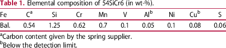
aCarbon content given by the spring supplier.
bBelow the detection limit.
Hardened and tempered springs coiled from SAE9254 are in use in the automotive industry, carrying the entire load of a vehicle and provide the required elasticity to absorb the road shocks. There have been increasing demands to improve the material performance with the aim to increase the fuel efficiency and reduce CO2 emission by reducing automotive components’ weight. As an attempt to satisfy such demands, the efforts have been focused to improve the spring material's mechanical performance (elasticity, strength, fatigue) by alloying additions and thermo-mechanical treatments [6 -9,15,16]. Coil surface is also shot-peened which generates compressive residual stresses to enhance the fatigue properties and significantly affects the ultimate life of the spring [15,16]. However, not much work has been reported on corrosion studies of 54SiCr6/SAE9254 coil spring steels. Materials of in-service automotive components degrade owing to dynamic loadings enhanced by environmental factors and global disparities such as heat, humidity, road conditions, salts resulting in decrease of components’ performance (called aging) and functionality. Corrosion is a commonly observed material degradation process in road suspension springs, affecting their mechanical properties and stiffness, threatening their structural integrity and life. Corrosion is a critical phenomenon which starts at the material's surface with its interaction with external environments and propagates with time and sometimes can lead to abrupt failure. As a general rule, two determinants initiate corrosion: (i) an active metal surface and (ii) a corrosive environment (mainly moisture and chemicals) which are abundantly available on the road in the form of water, dust/mud or salts. Although layered surface protection systems are applied to springs before deploying them in a vehicle various factors such as mechanical wear, stone chipping, dynamic loading or chemical compounds cause the protective coating to damage and corrosion to initiate. If localised corrosion (pitting) occurs, uneven surfaces and stress concentration fields are generated at the tip (bottom) of the pits acting as notches under loading and may cause cracking in the material in the worst scenario. In case of general corrosion, the spring rod diameter (material) will reduce with time, resulting in decreased complex dynamic stiffness. Different degrees of corrosion on various coils of a spring and/or various locations of a coil results in variable and uneven stiffness in four suspension springs of a vehicle and hence may affect the whole vehicle dynamic behaviour which may impact on drive comfort. Further, to achieve high-performance low-weight springs for reduced fuel consumption and environment protection, it intensifies the needs for better understanding of the corrosion damage by studying its evolution and growth.
A variety of coatings are in practice to achieve desired properties on components’ surfaces for protection against mechanical wear or corrosion for certain application. Phosphate treatments (zinc, manganese and iron) are commonly used in different industrial fields to fulfil various purposes, to provide corrosion/wear resistance, lubrication or electrical insulation [17,18]. Zinc phosphate (Zn.P) coatings are well known in the automotive industry as pre-treatment for painting. As an important surface treatment, they are used for corrosion protection on ferrous metals and can be applied by immersion or spraying, or a mixed spray-dip process [17]. Phosphate coatings are generally porous and are considered to favour/to improve paintability [19,20] offering better adhesion with the metal surface. The coating morphology, thickness (weight/area) and porosity depend on the applied process, conditions and additives [18,21,22]. The performance of the coating to resist corrosion is determined by the thickness and porosity [18 -22].
This work is focused on detailed microstructural analysis and corrosion characterisation of industrially manufactured and processed 54SiCr6 coil spring steel for better understanding the damage mechanisms involved when in service. Fabrication history and relative microstructure in rolled coil form and surface morphology with protection systems are described. The role of coating in corrosion protection and damage is characterised during testing. Corrosion characteristics of the steel, its initiation and growth mechanism as the influence of microstructure will be presented from various electrochemical experiments and microscopic characterisations of corroded regions. The study is a significant step for understanding spring degradation from metallurgical aspects and further development towards weight-reduced automobiles with better economy.
Materials and experimental work
Composition, manufacturing and heat treatment
Various low-alloy spring steels are used in various conditions to provide suspension, 54SiCr6 (AISI 9254) being common grade applied in the automotive industry. Steel 54SiCr6 is hot rolled to ‘BS EN 10089’ bars and hardened and tempered to be used as the spring steel. The investigated spring was hot-coiled and oil-quench-hardened at 880 °C with the aim to form fully martensite and tempered (about 30 min) at 410 °C to produce desired mechanical properties and elasticity. The material specifications are Young's modulus (E) 206 GPa, shear modulus (G) 78.5 GPa and hardness in the range of 575-610 HV with an average grain size of 8-9 µm. The chemical composition of the alloy analysed by X-ray fluorescence spectroscopy is given in Table 1. The Vickers hardness (HV) was measured on polished transverse-cross-section surfaces (200 µm from the edge to the middle of the rod at a distance of 500 µm) using a micro-hardness tester at 1 kg loads, for a dwell time of 10 s.
Surface treatments and coatings
All surface treatment processes were conducted by the manufacturer at the industrial scale. The spring alloy was single shot-peened with carbon steel cut-wire shots (avg. size 0.8 mm) after coil forming and heat treatment (Figure 1). Shot-peening generates 200-250 µm deep compressive residual stresses near the surface which enhances the crack initiation resistance under fatigue loadings. Shot-peened coils were passed through pre-cleaning and surface activation stages for spray Zn-phosphating and passivation processes, forming a zinc phosphate coating of 1.3-2.8 g/m2 and 10-20 µm crystal size. Coils were then rinsed with demineralised water and dried before applying a final powder paint coating. For this study, shot-peened and Zn-phosphated (before the final paint coating) coils were also collected from the manufacturing line.
Illustration of industrially applied spring protection system and various samples prepared from different directions (transverse and longitudinal cross sections).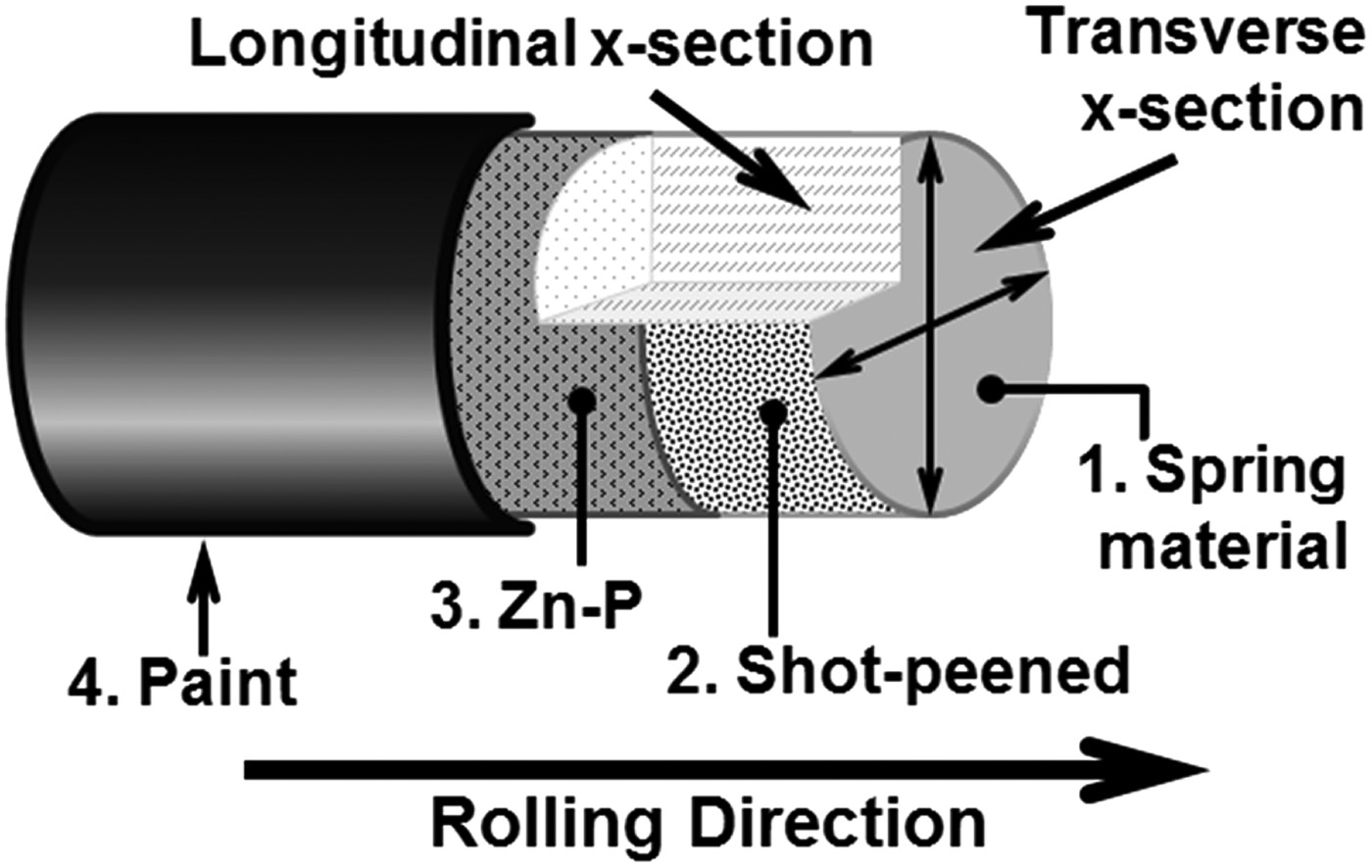
Microstructure and corrosion characterisations
Microstructural characterisations on finely polished (un-etched) and etched (2% nital – for 5 s) samples were conducted by optical and electron microscopy as well as X-ray diffraction (XRD) for phase identification. A Zeiss Ultra-55, field emission gun scanning electron microscope (SEM) equipped with in-lens, backscattered electron detector and energy-dispersive X-ray (EDX) detector was used for microstructural characterisation. Cross-sectional samples both in transverse and longitudinal directions (parallel to the rolling direction) were analysed. All samples were ground using ethanol instead of running water and carefully polished till 0.25 µm diamond paste and rinsed properly with ethanol during various steps to remove the remnant particles from grinding or polishing. A few samples were also polished using colloidal silica suspension for SEM studies.
Corrosion behaviour of the alloy was studied in naturally aerated 3.5 and 0.5% w/v NaCl solutions on standard polished transverse-cross-sectional as well as on actual external (shot-peened and Zn-phosphated) surfaces to better understand the corrosion initiation and propagation mechanism. However, the reliability of the paint coating was not studied in this work. Electrochemical measurements and corrosion tests were performed at room temperature, using a three-electrode cell consisting of test samples as working electrode, a saturated calomel electrode (SCE) as the reference electrode and a platinum as the counter or auxiliary electrode. The cathodic and anodic behaviours of the alloy were assessed in 0.5% NaCl through potentiodynamic/electrochemical polarisation. Samples were polarised from open circuit potential (OCP) to ± 150 mV at a scan rate of 6 mV/min. Electrodes were exposed to the solution for 1 h before the polarisation measurements to stabilise corrosion potential.
The potentiostatic tests were also conducted to study the material's accelerated corrosion. In the potentiostatic method, the potential of the working electrode is controlled using a potentiostat at a fixed appropriate value above the OCP. This instrument uses a feedback circuit to pass appropriate currents to the working electrode so that its potential measured against the reference electrode is maintained at the desired value, regardless of variations in current which correspond to changes in the rates of the corrosion reactions. The tested samples were held at a suitable potential of 100 mV above the OCP for different times (from 0.5 h to 5 days) after conditioning by immersion in corroding solution for 1 h to stabilise the free corrosion potential. All corrosion tested samples were also subjected to optical and SEM observations.
Results and discussion
Microstructure and phases
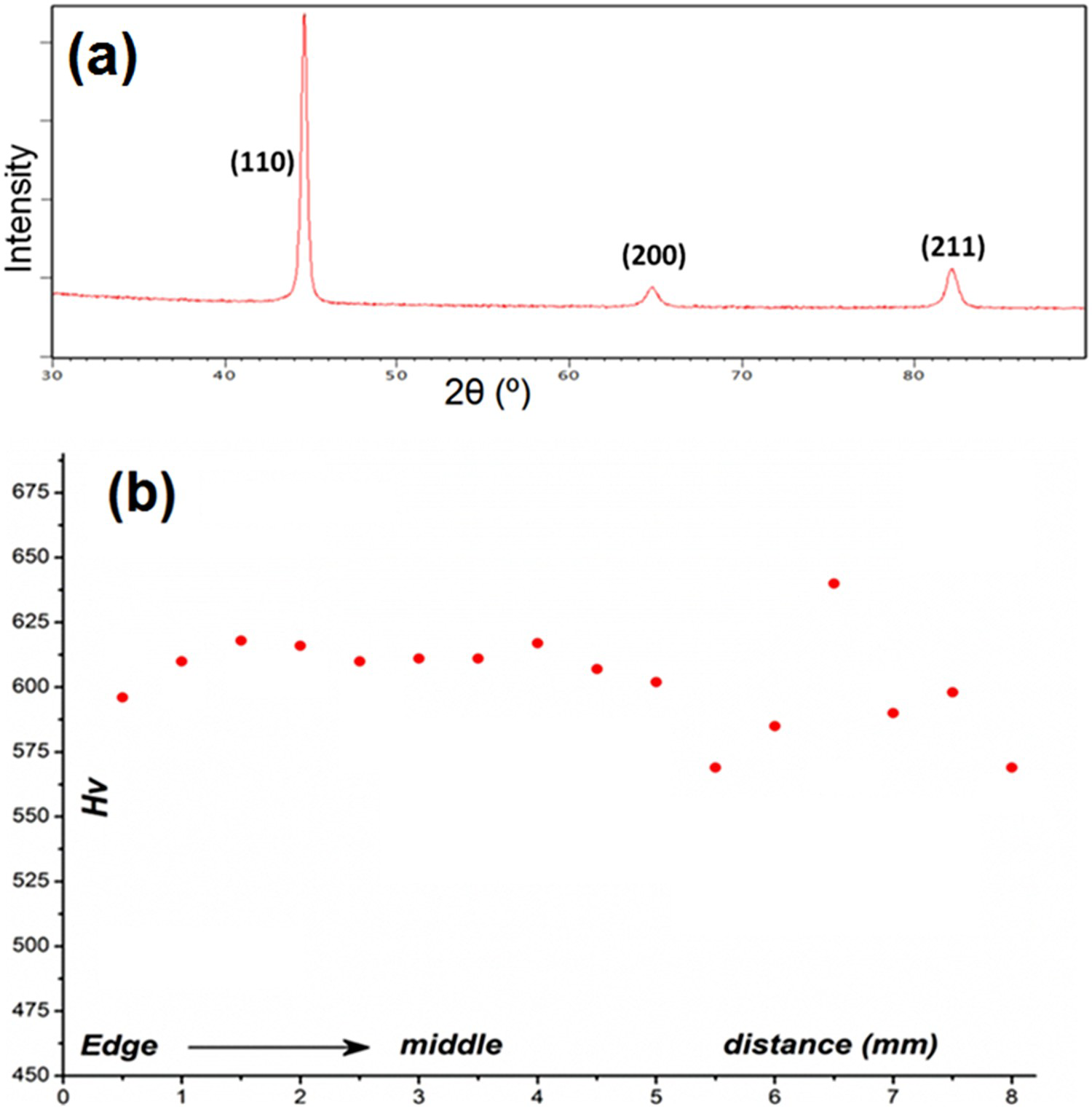
Polished surfaces were etched with freshly prepared 2% nital solution to reveal the general microstructure. As observed by optical and SEM, the microstructure was almost fully martensite as shown in Figure 2. Prior to coiling and quenching, the alloy was austenitised by induction heating (880 °C), subsequently carbon was homogenised in solid solution resulting in fine martensitic plates. The alloy was tempered at 410 °C for about 30 min. The decomposition of retained austenite, if present, starts at 450 °C [7], which was also evidenced during examination of samples as no precipitated carbides at grain boundaries were found in HR-SEM analysis. However, the presence of retained austenite was not confirmed by optical or SEM examination and XRD was conducted to further verify the bulk material phase which showed fully martensitic phase (Figure 3(a)). These microstructural results are in agreement with those already reported in the literature [7,10,15]. Figure 3(b) presents the Vickers hardness measured across the transverse-cross-sectional sample and the spread in values from the edge to the middle of the sample. The hardness range of the alloy given by the manufacturer is 575-610 Hv.
Martensite microstructure revealed after etching with 2% nital. Sample from transverse-cross section of coil viewed by optical microscope (a) and (b) SEM – secondary electron image, (c) SEM – mechanically deformed region (pointed by arrows) near shot-peened surface in the longitudinal x-section sample. (a) XRD of bulk material and (b) Vickers hardness (Hv1) measured across the sample's transverse-cross section from the edge to the middle.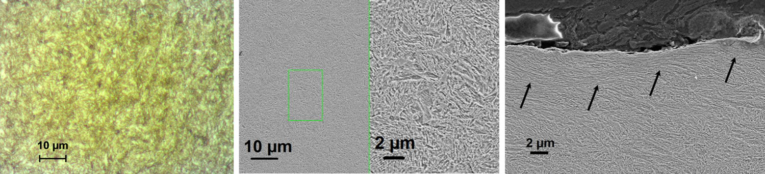
Inclusions
All steels contain non-metallic inclusions to a greater or less extent depending upon impurity levels and quality maintained during the melting, secondary metallurgy and casting processes. Polished (un-etched) surface was investigated by optical and electron microscopy to analyse the non-metallic inclusions present in the material. Four types of inclusions were found, including:
MnS inclusions Duplex oxy-sulphide inclusions Oxides of Al, Mg (with or without Ca, Si) Carbides of V, Ti, Nb
Type A and B inclusions are shown in Figure 4. Majority of inclusions analysed were sulphides or oxi-sulphides. MnS inclusions (type A) are common in steels depending upon the S content and are distributed as the chain-like formation or thin precipitates (Figure 4(a)). They are usually elongated in the rolling direction along the grain boundaries (Figure 4(b)) owing to deformation in the rolled material. Duplex inclusions (Figure 4(c), (d)) are oxide inclusions covered by MnS and are formed during steel melting and solidification. MnS segregates during casting on already existing impurities coming from the refractory lining, crucible materials or slag (Al2O3, MgO, silicates) [23]. During mechanical working, MnS undergo deformations while oxides are usually hard inclusions. Their EDX elemental analysis revealed Al-Mg-O with or without Ca, Si or sometimes complex composition associated with K and Na as well.
MnS inclusions in (a) transverse and (b) longitudinal x-section samples. Duplex oxy-sulphide inclusions where dark grey complex oxides of Al, Mg, Ca, Si (elements detected by EDX analysis shown from different regions) are surrounded by light grey MnS in (c) transverse and (d) longitudinal cross-section samples.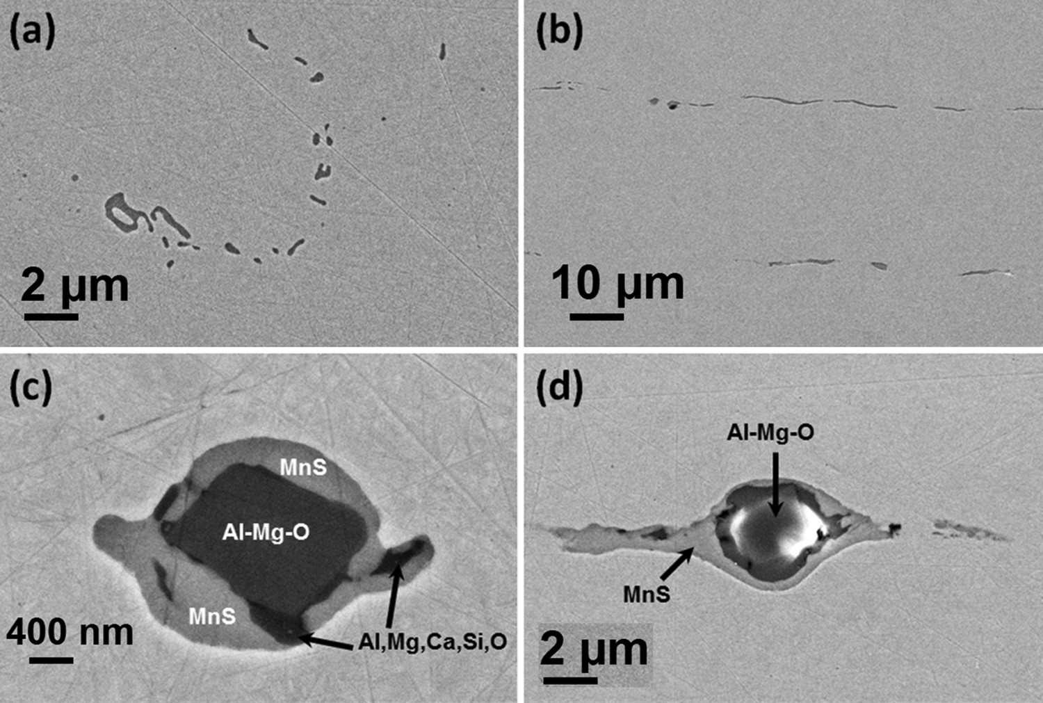
As a matter of fact, the alloy has approximately 0.75 wt-% manganese (Mn) and MnS inclusions are spread in the material. In low-alloy and carbon steels, from a corrosion point of view, MnS inclusions are more noble than the matrix, stimulating the anodic attack in the steel matrix immediately surrounding them [24]. While in stainless steels, MnS is anodic (less noble) as compared to the passive stainless steel and will be preferentially attacked in the corrosive environment [25]. Figure 5(a) reveals an overview of MnS distribution, shape and size in transverse (to the rolling direction) cross-section sample. The inclusions were found to be elongated in the rolling direction (Figure 4(b)) and continuous with large aspect ratio, such elongated inclusions are shown in Figure 5(b).
MnS inclusions (a) in transverse-cross section showing overall distribution (BSE image) and (b) optical micrograph showing elongated inclusions in sample parallel to the rolling direction.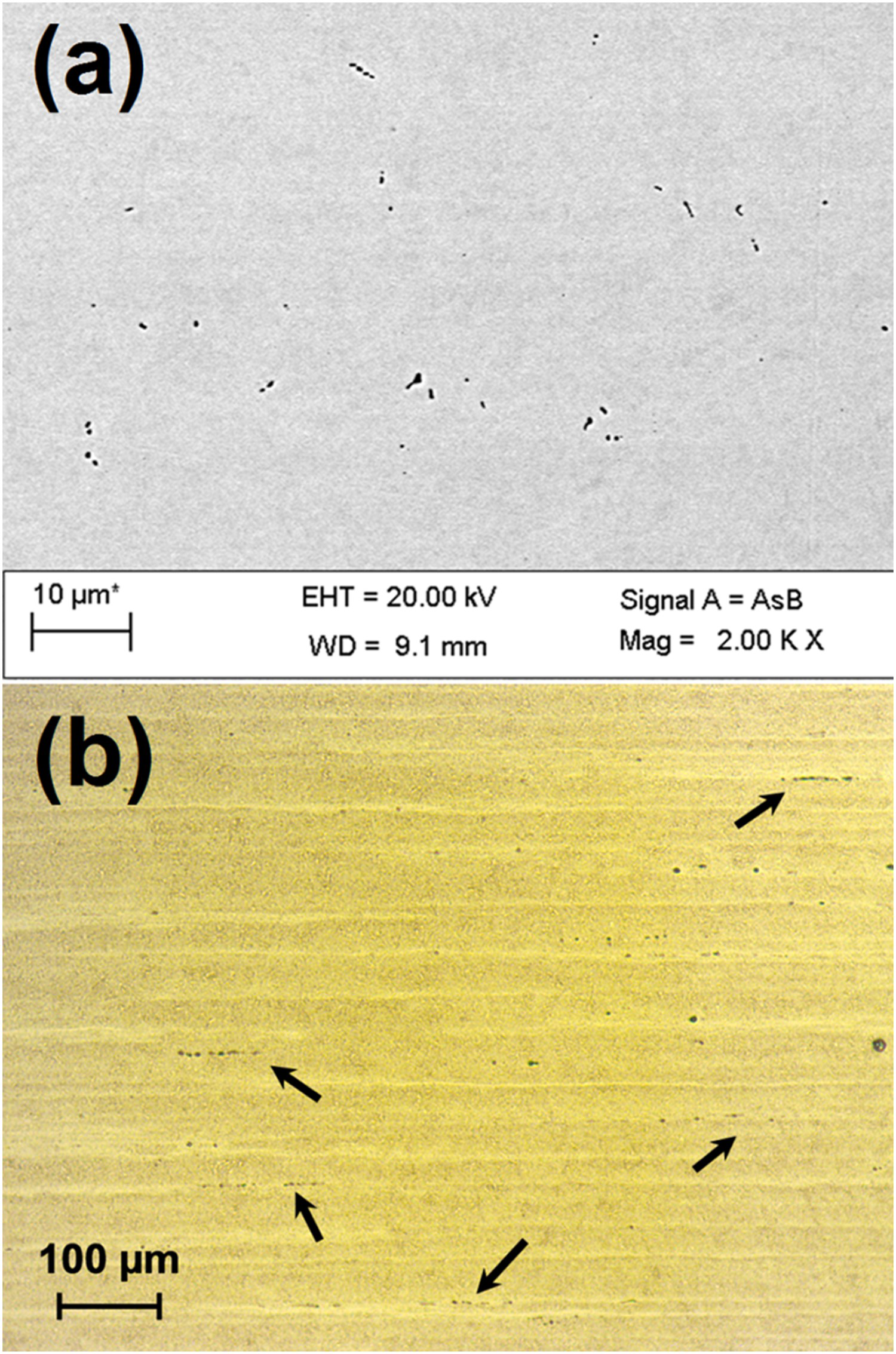
Beside the duplex oxy-sulphide inclusions, some oxide-based impurity inclusions (Type C) were also revealed in optical and SEM characterisation (Figure 6). Figure 6(a) shows a very large oxide inclusion (≈35 µm) while insets show SEM and EDX spectrum collected from this inclusion. This inclusion was about 1-2 mm distance from the edge of spring. Such inclusions can be detrimental for the material as they deteriorate the mechanical properties and may cause a failure under cyclic fatigue loading. High local stresses and defect (inclusion) size may lead to stress concentrations above the threshold of crack initiation and propagation [26]. Figure 6(b) and (c) shows the size and shape of a few other similar types of inclusions (Al-Mg-oxide).
Type C oxide inclusions: (a) optical, SEM and EDX spectrum (Al, Mg, Si, Ca, O) from a very large inclusion close to the edge, (b, c) a few Al-Mg-oxide inclusions.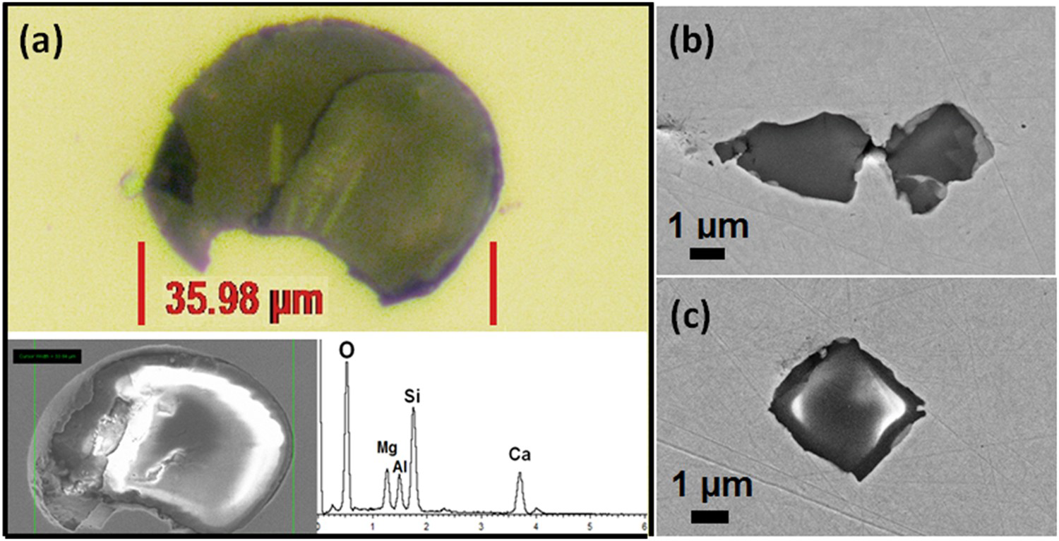
The fourth type of intermetallics (D) observed in the material were carbides of V, Ti and Nb (Figure 7) and sometimes were associated with MnS. These carbides are harder than the matrix and appeared as bright or yellow second-phase particles in optical microscopy.
Various carbide inclusions in steel (elements detected in EDX: Ti, V, Nb, C).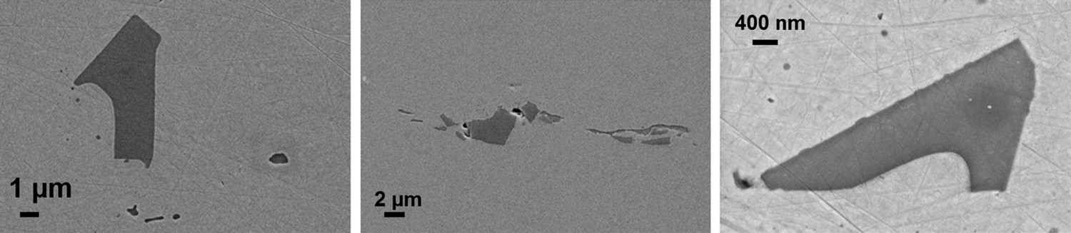
Coatings and near-surface morphology
As received shot-peened and Zn-phosphate coil surfaces are shown in Figure 8, where surface roughness and micro surface cracks can be noticed in the shot-peened surface (Figure 8(a), (b)). These surface cracks (Figure 8(b)) were produced during peening process owing to smearing or lapping of material as revealed in the transverse-cross-sectioned sample in Figure 8(c). During hot metal processing and heat treatment steps, scale (oxide layer) is formed on the metal surface. Since the shot-peening process is not subjected to remove scale (contrary to the sand blasting or others scale removing methods), Fe-oxide was also present on the coil surface as shown in the elemental EDX map (Figure 8(d)) and under the smeared materials (Figure 8(c)). MnS inclusions were not detected on the shot-peened surface of the coil when characterised by EDX mapping (Figure 8(d)), in contrast to the cross-sectional samples (Figure 5). SEM observations of coated samples revealed full surface coverage with Zn-phosphate having ultrafine and tiny flake-like crystals, as shown in Figure 8(e). The surface generated during peening (microcracks and roughness) were unchanged. Coating thickness was not revealed in any of polished cross-sectioned samples, although Zn and P were detectable by EDX analysis (Figure 8(f)), showing that short-time spray process generated a thin layer of Zn.P, unlike the dip process.
Overview of (a) shot-peened coil surface and (b) magnified SEM image showing overlapped material and microcracks while (c) is the cross-sectional view of shot-peened surface revealing Fe-oxide under smeared material. Elemental EDX map (d), showing oxide distribution (O Kα1) on shot-peened coil surface and results for Mn and S. Coil surface after Zn phosphate coating (e) and EDX spectrum (f) from Zn.P coating.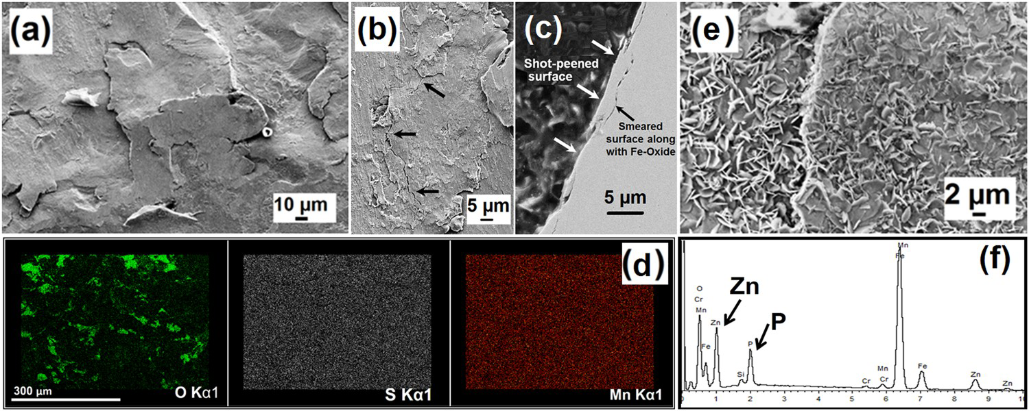
Near the surface in cross-sectional samples, almost 2-3 µm mechanically deformed region was observed (Figure 2(c)) which is probably as a result of shot-peening. Paint coating was measured from various rings of the coil spring. The variations in thickness were noticed on each analysed sample from various rings and coating was found to be in the range of 28-120 µm.
Corrosion characteristics
OCP
The OCP of 54SiCr6 HSLA was monitored on polished cross sections (transverse and longitudinal) as well as external spring surfaces (both shot-peened, and final Zn.P coated) in 0.5% (w/v) NaCl solutions while the only transverse-cross section in 3.5%. Figure 9(a) shows representative OCP curves among various tests conducted for each type of surface and exhibits their behaviour over 48 h immersion time. The measured free corrosion potentials of several polished and shot-peened samples in 3.5 and 0.5% NaCl environments were almost ≈–700 (± 20) mVSCE (Figure 9(a)) and no clear difference was noted. From various tests and immersion times, it was observed that potential versus time curves were not identically stable until the first few hours (e.g. 4-6 h). The corrosion potentials (OCP) for the first few hours were not reproducible for identical specimens, which may affect the polarisation and accelerated corrosion results, as to be discussed later in the polarisation section.
(a) OCPs from polished transvers cross-section (in 3.5 and 0.5% NaCl) and longitudinal cross-section, shot-peened and Zn-phosphated surfaces (in 0.5% NaCl), (b) a typical anodic and cathodic polarisation curve among several tests (potential versus log-current density) assessed on transvers cross-section polished surfaces in 0.5% NaCl solution at room temperature. (c) Sample immersed for 30 sec in NaCl solution showing corrosion initiation zone and nearby un-attacked areas with different inclusions (MnS: white arrows).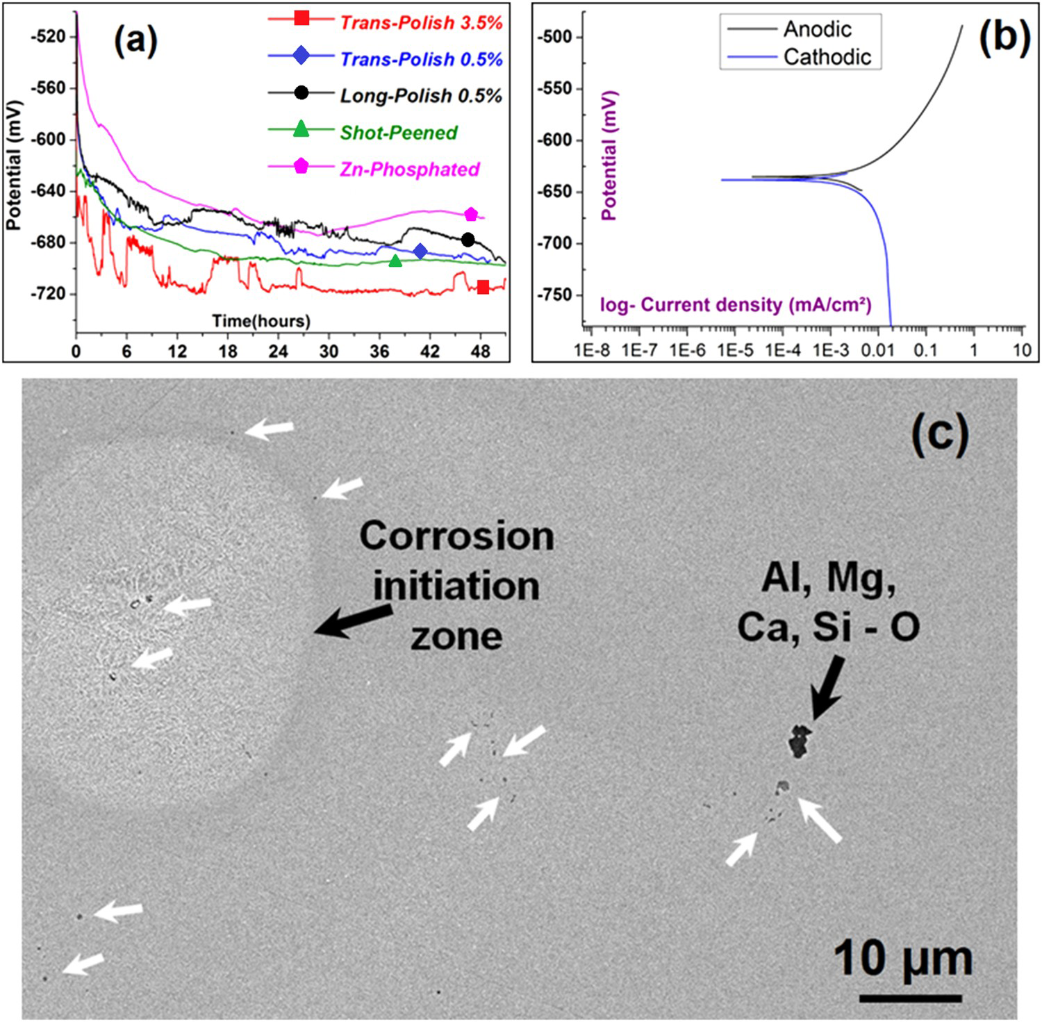
To investigate the corrosion initiation, samples were immersed in NaCl solution for short intervals (5 min to 30 s) and the zones where attack had initiated were analysed in SEM. Close examinations of corroded zones revealed that MnS inclusions are more active as compared to the other Type-C inclusions (oxides of Al, Mg, Ca and Si). Such a zone is shown in Figure 9(c) where corrosion is initiated in surroundings of MnS but not Type-C inclusion. Duplex oxy-sulphide inclusions were also responsible for initiation of corrosion, probably owing to the present of MnS. Various zones were analysed to find if the size/shape or distance between MnS inclusions plays a role to initiate corrosion but no such relation could be established.
As a matter of fact, the grain morphologies in transverse-cross section and external longitudinal surface are not the same. The polished surface has many exposed MnS inclusions (Figure 5) acting as active sites while the external shot-peened surface of spring is smeared and has deformed grain structure covered with Fe-oxide scale, resulting in less exposed MnS active sites (Figure 8(d)). Variations in the curves of all polished surfaces over time (Figure 9(a)) show initiation of different corrosion activities on the exposed surface, however, no significant behaviour is observed in OCP of shot-peened deformed surface which has compressive residual stresses. Among different OCP tests of shot-peened surface samples, considerable variations in the potential values were noted which may be related to Fe-oxide scale or smeared deformed layer present on the peened surfaces.
On the other hand, it can be perceived that the OCP value of Zn-phosphated surface had shifted towards more positive values (nobler) than the shot-peened substrate (Figure 9(a)). Phosphate coatings provide a barrier and act as an interlayer between the metal and corrosive medium (electrolyte) and prevent corrosion of the substrate. The shift in corrosion potential is a function of coating thickness or density (wt/area) and morphology (structure, compactness, coverage and porosity) [18,20 -22]. Thicker the coating, lesser the porosity and hence yields in better protection characteristics against corrosion.
It is established that phosphate coatings are porous insulators. Their insulation protection and corrosion failure mechanisms have been elucidated by Weng et al. [18]. The corrosion occurs on the exposed steel substrate. The electrolytic solution (Cl− ions) diffuses into the pores and reaches the substrate through the coating [17]. The corrosion products and reactants are hindered under the film at the interface causing the corrosion to spread along the substrate surface, known as under-film corrosion of phosphated steels. During the test (Figure 9(a)), OCP value of the phosphated steel was gradually reduced close to that of the base metal with the passage of time, indicating the deterioration of coating and that the substrate was exposed to the solution. The literature suggests that corrosion resistance of zinc phosphate coating is limited compared to manganese phosphate and shows less protective characteristics [for instance, Ref. [18]]. The main purpose of zinc phosphate application on springs is to provide a better adhesion between the epoxy paint and the alloy surface.
Polarisation
Polished transverse-cross-sectional samples were polarised up to 150 mV from free corrosion potential (OCP), respectively. OCPs recorded for all samples were found to be between −610 and −640 mVSCE after 1 h immersion. Figure 9(b) indicates a typical ‘potential versus current density’ curves for anodic and cathodic reactions of such samples. The onset of diffusion control at an early stage in oxygen dissolved solution system shows that corrosion of this steel is controlled by mass transportation. It is noted that the anodic polarisation of this steel displays a characteristic of active dissolution and no passive behaviour appears.
Potentiostatic held experiments are generally conducted to study the passive state of a material under corrosion however in this case these tests were done for accelerated corrosion to study microstructural relation to corrosion propagation over time. The polished transverse-cross-sectional samples were held at specific potentials, +100 mV versus OCP, for various times. OCP and current densities recorded for samples held at + 100 mV versus OCP for 6 h (Sample A) and 18 h (Sample B) are shown in Figure 10. The two curves seem to have identical behaviour; however, values of current are different, exhibiting different corrosion rates (Figure 10(b)). This difference can be related to the different static potentials at which samples were held. As discussed earlier, OCP values were not reproducible in the first few hours for identical specimens. Sample B in Figure 10(a) with higher OCP (≈−625 mVSCE) was tested at higher i.e. more anodic potential (≈−525 mVSCE) and shows higher recorded current density and hence the higher corrosion rate. As a matter of fact, it was difficult to achieve close OCP values (after 1 h immersion) and hence the corrosion rates in various potentiostatic polarised samples were not the same.
(a) OCP curves during 1 h immersion of samples A and B before potentiostatic polarisation in 0.5% NaCl, (b) current densities recorded versus time when held for 6 and 18 h at + 100 mV versus OCP.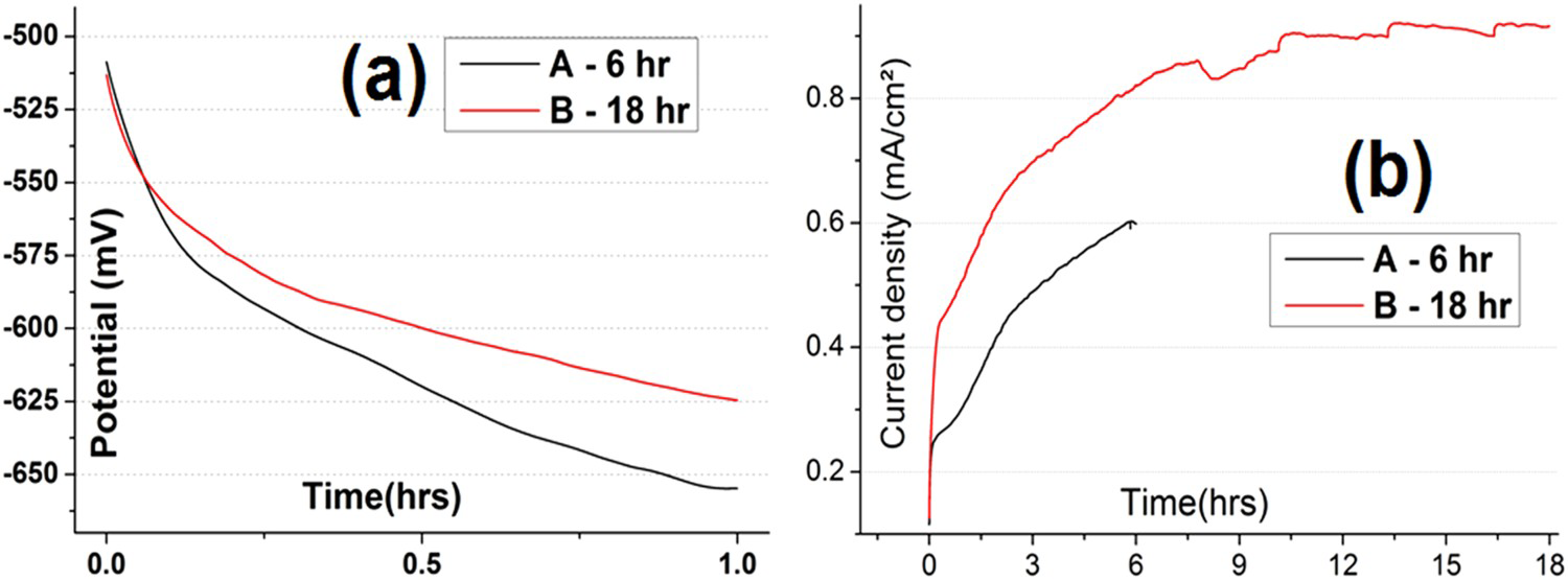
The influence of grain elongation and inclusion distribution
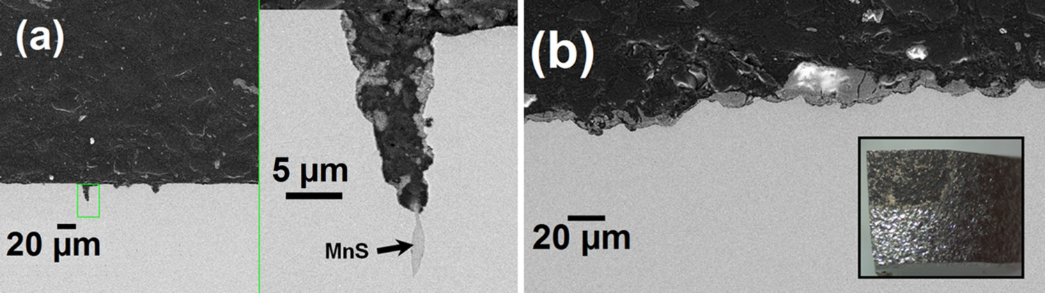
Both pitting and general corrosion occurred during accelerated testing as can be seen in the surface as well as cross-sectional views of samples (optical and SEM images) in Figure 11. The width, depth and density of pits increase with increasing the test time to 18 h (Sample B). MnS inclusions were found at the growing tips of many pits and further confirmed by EDX in SEM (Figure 12(a)). It is evident that in transverse-cross-sectioned tested samples A and B, majority of pits had larger depths than their widths (Figures 11(e) and 12(a)). As discussed in earlier sections, MnS inclusions are very active in this steel to initiate corrosion and microstructural investigations revealed that the grains and MnS inclusions are elongated in the rolling direction (Figure 5(b)). Hence, it can be concluded that when transverse-cross-sectioned samples were tested, the corrosion started likely in the vicinity of MnS inclusions (Figure 9(c)) and propagated along the inclusions resulting in deep pits formation in the direction of elongated grains. It can be assumed that the corrosion propagation and pits morphology will be different in longitudinal cross-sectional samples when exposed to corrosion. Likewise, the outer surface of spring which is exposed during service and is subjected to corrosion can have different pits morphology corresponding to the surface microstructure. To confirm this and determine the real corroding scenarios, the final external surfaces of spring (shot-peened and phosphated) were also potentiostatically held at + 100 mV versus OCP for 18 h and 5 days. Figure 12(b) shows the cross-sectional view of corrosion morphology in surface sample accelerated corroded for 5 days. The corrosion progression is more general type rather than pitting when the external surface of spring is exposed (Figure 12(b)). Because the grains of external surface are in the longitudinal direction and hence resulting corroded regions are wider than the depth in contrast to the transverse-cross-sectioned sample results (Figure 11). For instance, no pit was observed in the external surface sample when tested at 100 mV above the OCP for 5 days while in the transverse-cross-sectioned sample, about 20 µm deep pit is formed only in 6 h (compared in Figure 12(a), (b)).
SEM images from surfaces view of tested samples A (a, b) and B (c, d) and depth profile of corrosion damage from (optical) cross-sectional view (e). Morphology of corrosion revealed in SEM-cross-sectional view for samples held potentiostatically, (a) when transverse-cross section surface exposed for 6 h, showing a typical higher depth/width pit with MnS inclusion at growing front of the pit. (b) Shot-peened external surface sample tested for 5 days, while stereo surface view (in-set) after 18 h exposure.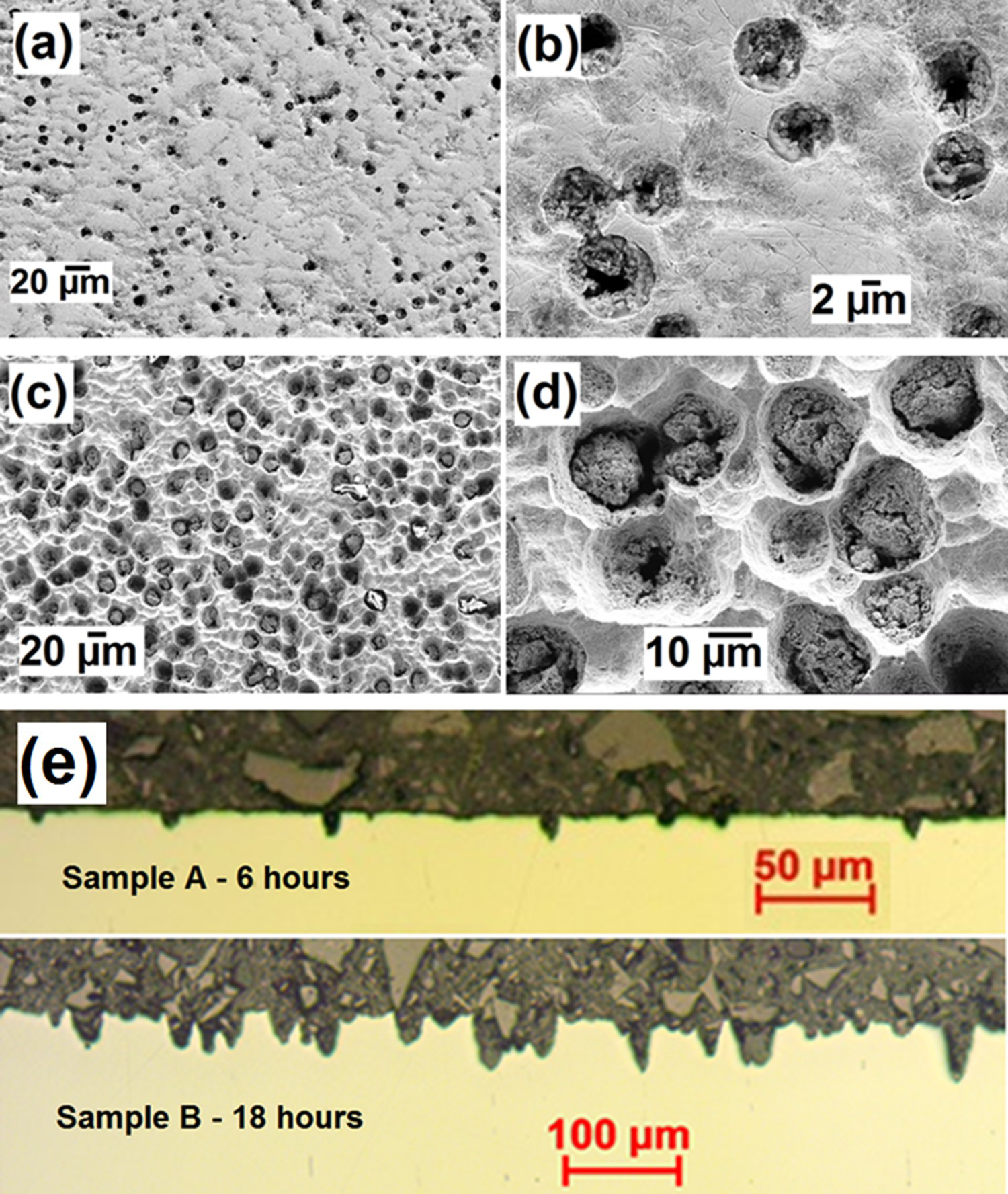
This characterisation and testing are essential to understand the impact of microstructure evolved during spring manufacturing and surface treatments on the corrosion behaviour during service. In a parallel work, the corroded springs from service and proving ground tests are also under investigation to simulate the effect of corrosion damage on performance [27]. The aim of that work is to develop material models for automotive spring degradation owing to corrosion and to study performance (mechanical properties) loss over time (aging) during service. The results from current publication and related work will be used to develop more accurate finite element models.
Summary
In the present work, the evolved microstructure and corrosion behaviour of hot-coiled, quenched and tempered 54SiCr6 steel springs with shot-peened and Zn-phosphated surfaces were investigated. The material's microstructure uniformly consists of fine-plate martensite mainly with MnS inclusions distributed at grain boundaries along with traces of carbides and oxide/slag inclusions. The grains and sulphide inclusions are present as stringers elongated in the rolling direction while surface has a 2-3 μm shot-peen generated mechanically deformed region. The following findings can be drawn:
The material's stable OCP in 3.5/0.5% NaCl solutions was about –0.7 VSCE without showing significant change after shot-peening. MnS inclusions were active in martensite matrix and mainly responsible to start corrosion in surrounding matrix owing to their cathodic nature. Spray Zn-phosphating produced a thin layer of Zn.P which pushed the OCP to a bit noble side (more positive); however, OCP reduced close to that of base metal within 12 h in NaCl solution which reflects the interaction of electrolyte solution with the base metal. Corrosion propagation during accelerated tests showed that damage growth in a given environment is affected by microstructure and inclusion morphology. The elongated MnS inclusions and grain structure evolved during fabrication have an impact on corrosion and the severity of the attack is more pronounced in the transverse direction. When the transverse-cross-section is exposed for the attack in solution immersion, corrosion propagates and pits with higher depth-to-width ratio are generated owing to directional microstructure. The corrosion attack observed after accelerated tests on external shot-peened or Zn-phosphated surfaces was of a general type.
Footnotes
Acknowledgements
The authors of the work are grateful to Mr Ian Knight, Mr Lorenzo Gagliardi and Mr Elliot Hemes of JLR for providing materials and technical support during the project. Dr M. A. Yar acknowledges Dr Alexander Cassell, PDRA at School of Materials, The University of Manchester, for his assistance and many fruitful discussions during this research work.
Disclosure statement
No potential conflict of interest was reported by the authors.