
Abstract
This paper reports a comparison of the gait patterns of trans-femoral amputees using a single-axis prosthetic knee that coordinates ankle and knee flexions (Proteor's Hydracadence® system) with the gait patterns of patients using other knee joints without a knee–ankle link and the gait patterns of individuals with normal gait. The two patient groups were composed of 11 male trans-femoral amputees: six patients had the Hydracadence® joint (Group 1) and five patients had other prosthetic knees (Group 2). The reference group was made up of 23 normal volunteers (Group 3). In this work, trunk, hip, knee, and ankle 3-D motion was assessed using the VICON® system. Kinetic data were collected by two AMTI® force plates, and the knee moment was calculated via the 3-D equilibrium equations. An original questionnaire was used to assess the participants' activity level and clinical background. The results reveal that, during stance, all knee types guaranteed security. After heel strike, the plantar flexion of the ankle enabled by the Hydracadence® prosthesis seems to increase stability. During swing phase, hip and knee sagittal motion was nearly the same in both Group 1 and Group 2. By contrast, hallux and sole vertical positions were significantly higher in Group 1 than in Group 2; thus, it seems the link between the ankle joint and the knee joint makes foot clearance easier. No alteration of the lateral bending of the trunk was observed. The protocol proposed in this paper allows a functional comparison between prosthetic components by combining clinical data with objective 3-D kinematic and kinetic information. It might help to determine which prosthetic knees are best for a specific patient.
Introduction
Gait patterns of trans-femoral amputees differ from normal gait. Since muscles are absent in the prosthetic limb, a substitute stabilization device has to be found. Many devices have been developed to guarantee security during the stance phase by avoiding any uncontrolled flexion, such as mechanical knee brakes, hydraulic stance phase control, and polycentric knees. Prosthetic knees also have to allow mobility between the thigh and lower leg during the swing phase. Many devices accelerate the lower leg during the swing phase, and pneumatic or hydraulic systems also control the deceleration of the prosthetic leg at the end of this phase in order to minimize the impact transmitted to the socket (Fitzlaff and Heim 2002). Among all prosthetic knees, only one coordinates ankle and knee motions: the Proteor Hydracadence® prosthetic knee, a single-axis joint with a hydraulic swing-phase control system. Its uniqueness lies in the mechanical link between the prosthetic knee and the prosthetic ankle that allows dorsal flexion of the ankle when the knee flexes more than 20°. It is designed to facilitate foot clearance by controlling the height of the sole. The Hydracadence® system also allows plantar flexion of the ankle at heel strike. The intended functional consequence is more security during the stance.
There are currently few objective criteria for choosing a prosthetic knee for a specific patient because of the lack of 3-D kinematic comparisons of gait with several prostheses. Indeed, few studies have been carried out to compare different prosthetic knee joints. De Vries (1995) made a strength and weakness analysis of eight different polycentric knee joints. The conclusions drawn from this study are limited, however, because the data were based on the theoretical mechanical behaviour of the prosthetic knees and not on their behaviour during gait. Perry et al. (2004) assessed energy expenditure of a bilateral trans-femoral amputee walking with three different types of prostheses, and showed the efficiency of the Otto Bock C-leg® compared to the stubby and the non-computerized Mauch® SNS. However, the study was conducted with only one amputee and the functional gait analysis only concerned the C-leg®. Finally, Boonstra et al. (1996) evaluated gait patterns of 28 trans-femoral amputees whose prostheses incorporated a 4-bar linkage knee joint with either mechanical swing-phase control (3R20®) or pneumatic swing-phase control (Tehlin®). Their study was based on kinematic analysis in the sagittal plane and questionnaires about the participants' feelings. Measurement of velocity, phase duration, and gait symmetry provided objective, quantitative elements in addition to the more subjective measures of participants' feelings. However, the comparison only concerned swing-phase behaviour in one plane. There was no comparison with normal gait.
The purpose of this study was to describe gait patterns of trans-femoral amputees using two different single-axis knee joints with a hydraulic swing-phase control, and especially to study the effect of a mechanical knee–ankle link. At the same time, gait patterns of amputees were compared to normal gait in order to evaluate the functionalities of each knee joint. An objective 3-D kinematic and kinetic gait analysis revealed strategies chosen in response to security problems during the stance phase and kinematic coordination between hip, knee, and ankle motion during the swing phase. Moreover, an original questionnaire was used to assess participants' activity level and feelings.
Methods
Participants
In total, 11 male trans-femoral amputees were considered during their clinical gait-analysis examination. No ethical approval was required, since the protocol of our study was completely non-invasive and painless. Moreover, gait analysis was added to the usual clinical evaluation only if both the patient and their doctor agreed. The protocol was performed with a medical doctor and a prosthetist.
All the amputees included in the study walked with their own prosthesis and their own shoes. None had undergone amputation for vascular reasons. They were divided into two groups. Group 1 comprised six patients who all used the Proteor Hydracadence® prosthetic knee. The mean age was 58.5 years (range 45–71 years); amputation had been performed an average of 32.8 years previously (range 19–41 years). One of the patients (S31) uses feet with a built-in carbon leaf system. Participant S32 is used to walking with a stick but this patient walked without assistance during the experiment. Details of the participants in Group 1 are presented in Table I.
Participant characteristics of Group 1 (with Hydracadence® knee joint)
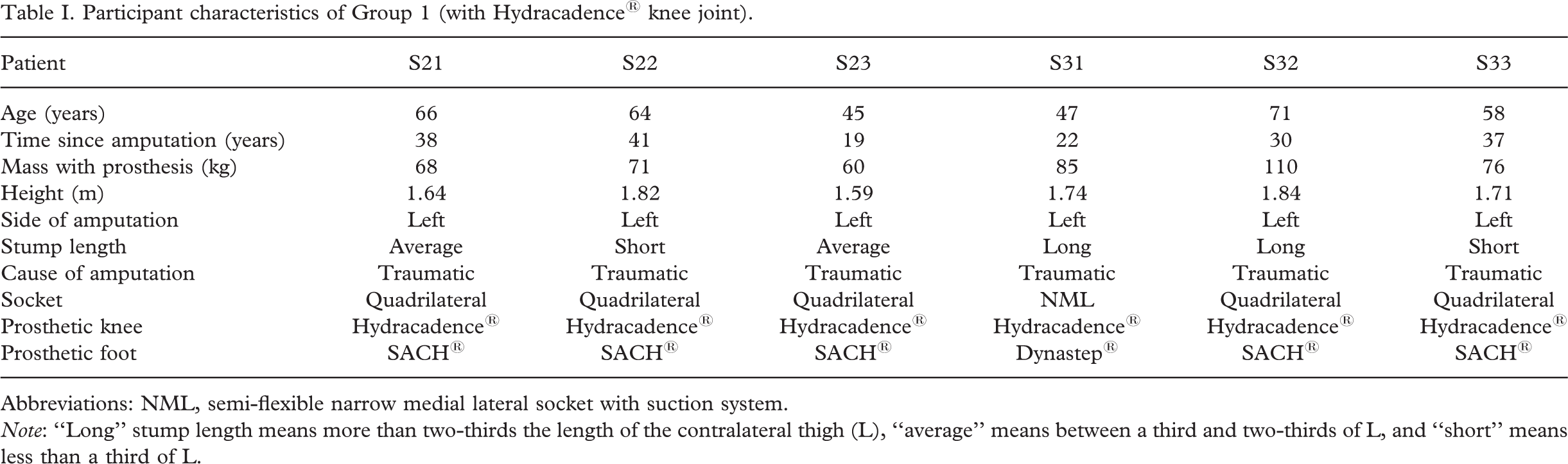
Abbreviations: NML, semi-flexible narrow medial lateral socket with suction system.Note: “Long” stump length means more than two-thirds the length of the contralateral thigh (L), “average” means between a third and two-thirds of L, and “short” means less than a third of L.
Group 2 comprised five patients who used single-axis prosthetic knees with a hydraulic swing-phase control device, but with no knee–ankle link. The mean age was 53.4 years (range 34–71 years) and the mean time since amputation was 34.6 years (range 11–56 years). Details of the participants in Group 2 are presented in Table II.
Participant characteristics of Group 2 (with other single-axis, hydraulic swing-phase control prostheses)
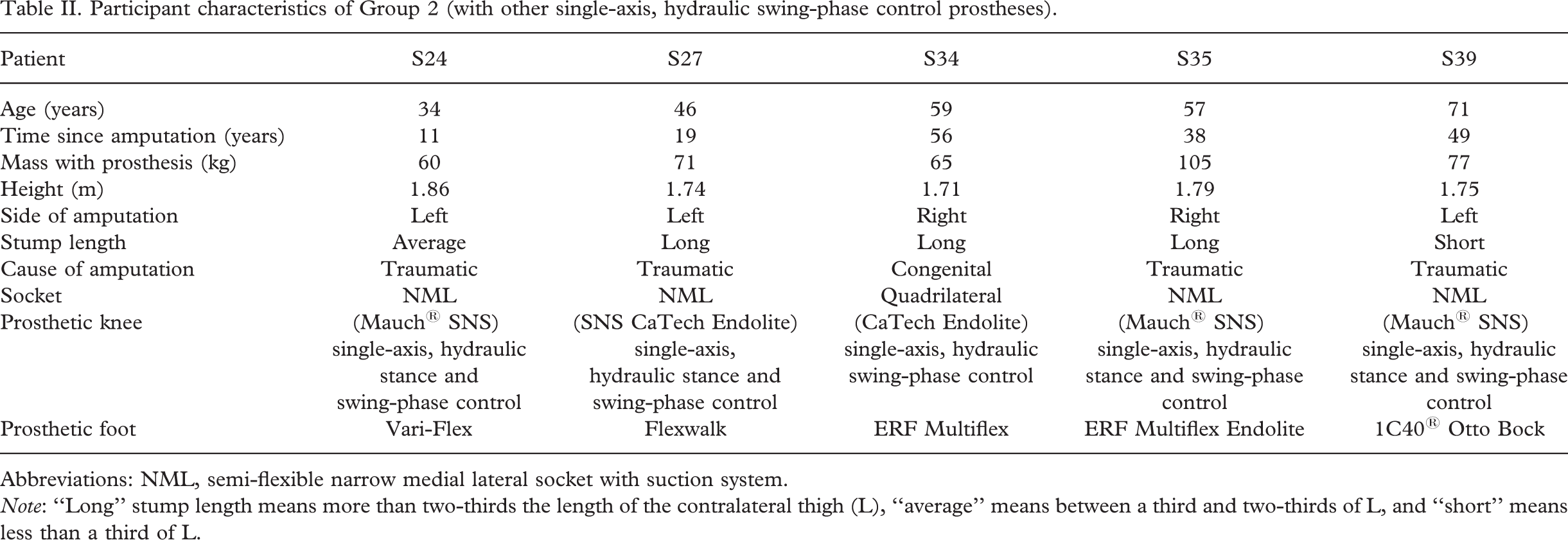
Abbreviations: NML, semi-flexible narrow medial lateral socket with suction system.
Note: “Long” stump length means more than two-thirds the length of the contralateral thigh (L), “average” means between a third and two-thirds of L, and “short” means less than a third of L.
From 53 normal participants who have no problems walking, we selected a reference group (Group 3) composed of 23 participants in the age range of the amputees (34–71 years). The mean age of Group 3 was 50.9 years. All reference-group parameters are expressed for the left side.
Protocol
The study was performed at the CERAH (Centre d'Etude et de Recherche sur l'Appareillage des Handicapés, France). The materials and experimental procedure are the same as in the protocol described by Goujon et al. (2005): kinematics and kinetics were collected respectively by means of an optoelectronic motion system (Vicon® 524) and two force plates (AMTI®).
Anthropometric measures of the lower-limb segments—length and diameter of the foot, shank, and thigh—enabled the personalization of an anthropometric model representing these segments with simple geometric shapes. Thanks to this model, supposing that the density is homogeneous and the mass distribution is axisymmetrical, the mass and the position of the centre of mass was evaluated for each segment in order to calculate the joint moments due to the gravitational force on the segments. The ground reaction force and moments were measured by the AMTI® force plates.
A questionnaire, created with a medical doctor, was added to the initial protocol (see Appendix I for an English translation of the original French-language questions). This questionnaire is divided into three parts. Part 1 evaluates the activity level of the participant. Since it is difficult for amputees to assess the distance and time they are able to walk without rest, information about their gait activity is preferred. Thus, the questionnaire takes into account not only ambulation during leisure time or job activity, but also accommodation type and daily small journeys. Part 2 is about the participant's medical background, and Part 3 assesses the participant's feelings concerning the prosthetic components' characteristics.
Data analysis
Data were processed using Matlab® software. Filtering was performed using the Woltring method automatically included in the VICON® post-processor.
Joint kinematics. Joint kinematics was calculated using the methods described by Goujon et al. (2005):
Angular-speed calculation. The relative angular speed between the thigh and the lower leg was calculated from VICON®-collected kinematic data. A spline, corresponding to the evolution of the relative angle between the thigh and the shank during gait, was calculated for each trial in the three planes. The derivative of the spline function was then calculated for each trial. Finally, the angular speed was calculated as the average of the previous derivatives.
Foot-clearance evaluation. Foot clearance depends on the magnitude of the hip flexion and the knee flexion. When hip flexion is inadequate, ankle dorsiflexion may not be sufficient to increase foot clearance, since the sole could drag along the floor. Thus, foot clearance is evaluated from the vertical positions of both the hallux and the middle of the metatarsals during the swing phase.
Two minima were observed in the curve representing the vertical position of the hallux for normal participants. The first is a global minimum and corresponds to the toe-off. The second is a local minimum and appears just before the ankle returns to its neutral position (when foot anatomical frame is perpendicular to the shank anatomical frame). The minimal vertical position of the hallux during swing phase is the difference between these two vertical minima.
The height of the sole during swing phase was evaluated from the vertical position of the middle of the first and the fifth metatarsi. The height of the sole corresponds to the difference between the minimal vertical position of the middle of the metatarsi during swing phase and the minimal position during stance.
Knee moment calculation
Mechanical action exerted by the thigh on the leg was calculated via 3-D equilibrium equations from ground reaction forces and moments. The inertial terms were neglected. Thanks to the anthropomorphic model, created for both sound and prosthetic limbs and described above, lower-limb inertial segment parameters (mass and position of the centre of mass) were evaluated. These parameters are necessary to express knee-joint forces and moments due to the weight of the leg. To compute the force and moment equations at the same time, the wrench notation was used. The moment representing the action of the thigh on the leg is called the ‘knee moment’. The moment about the media-lateral axis of the knee, which balances the moments due to body mass and the load transmitted by the contra-lateral leg is called the ‘knee sagittal moment’. To compare the action of this component at the beginning of stance phase, the area under the knee sagittal moment curve is calculated between 10% and 20% of the gait cycle. This parameter, representing the average value of the moment when the weight is being transmitted to the leg during single-limb stance on the prosthetic side, is called the average knee moment (KA).
Questionnaire analysis
Participants' activity levels were assessed via a scoring method. The participant's level of activity, evaluated on 24 points, takes into account the housing (3 points), the job (7 points), leisure activities (9 points) and other displacements (9 points). The greater the number of points, the greater the inferred activity level. Participants' activity levels were classified into five categories: poor (0–6); basic (7–10); average (11–14); high (15–18); or very high (19–24) activity. The calculation of the activity score is described in Appendix II.
We selected the below parameters for the comparison study:
Walking speed and activity score to evaluate global gait efficiency. During the stance phase: sagittal plane knee motion and KA in response to security demand; and vertical and anterior–posterior components of the ground reaction force (in the sagittal plane, respectively upwards and backwards) and ankle motion in order to evaluate how loads are transmitted through the prosthesis. During the swing phase: sagittal plane ankle and knee motions; sagittal plane hip motion to show how the prosthesis is actuated; and foot clearance so as to describe lower-leg kinematics.
Statistical analysis
Differences between groups were evaluated with the Wilcoxon non-parametric test, which is particularly adapted to small groups (fewer than 8 participants). The level of significance was set at p = 0.05.
Results
Global evaluation
Age and time since amputation
The mean age and time since amputation were similar in both amputee groups. Mean age was 58.5 ± 10.6 years in Group 1, compared with 53.4 ± 14.0 years in Group 2 (p = 0.53), and time since amputation was 31.2 ± 9.0 years in Group 1, compared with 34.6 ± 19.2 years in Group 2 (p = 0.79).
Activity
Participants in Group 1 were slightly less active than participants in Group 2, but the difference was not significant (the activity score was 10.5 ± 4.3 in Group 1 and 14.4 ± 0.6 in Group 2, p = 0.13).
Walking speed
Amputees walked significantly more slowly than did the normal participants (mean speeds of 1.0 ± 0.2 m/s and 1.2 ± 0.1 m/s, respectively, p = 0.011). No significant difference was found between Group 1's and Group 2's mean walking speed (1.0 ± 0.2 m/s and 1.1 ± 0.2 m/s, respectively; p = 0.54).
Influence of age
For all the traumatic amputees of both Groups 1 and 2, the older the participants, the slower was the gait observed. However, the relationship between age and activity level was less clear: in Group 1, the older the participants, the lower the activity level, but this is not true for Group 2. (These relationships were not statistically significant.)
Gait analysis: During stance phase
As expected, the duration of stance on the prosthetic limb was 1–5% shorter than for normal participants. The ratio of the duration of the stance phase on the prosthetic side to that on the normal side characterises the symmetry of the gait. Groups 1 and 2 combined had an asymmetrical gait compared with that of Group 3 (mean ratio of 0.9 and 1.0, respectively, p < 0.0001), but no significant difference was found between Groups 1 and 2 (0.9 ± 0.05 and 0.9 ± 0.03, respectively, p = 0.47).
Security during stance
Kinematics and kinetics of the trans-femoral amputees during stance were completely different from the kinematics and kinetics of those with normal gait. The sagittal knee moment generates the complete extension of the prosthetic limb throughout the stance phase. By contrast, the flexion moment, which appears between 0% and 25% of the gait cycle, makes the knee flex until 11° at the beginning of the stance phase (Figures 1 and 2).
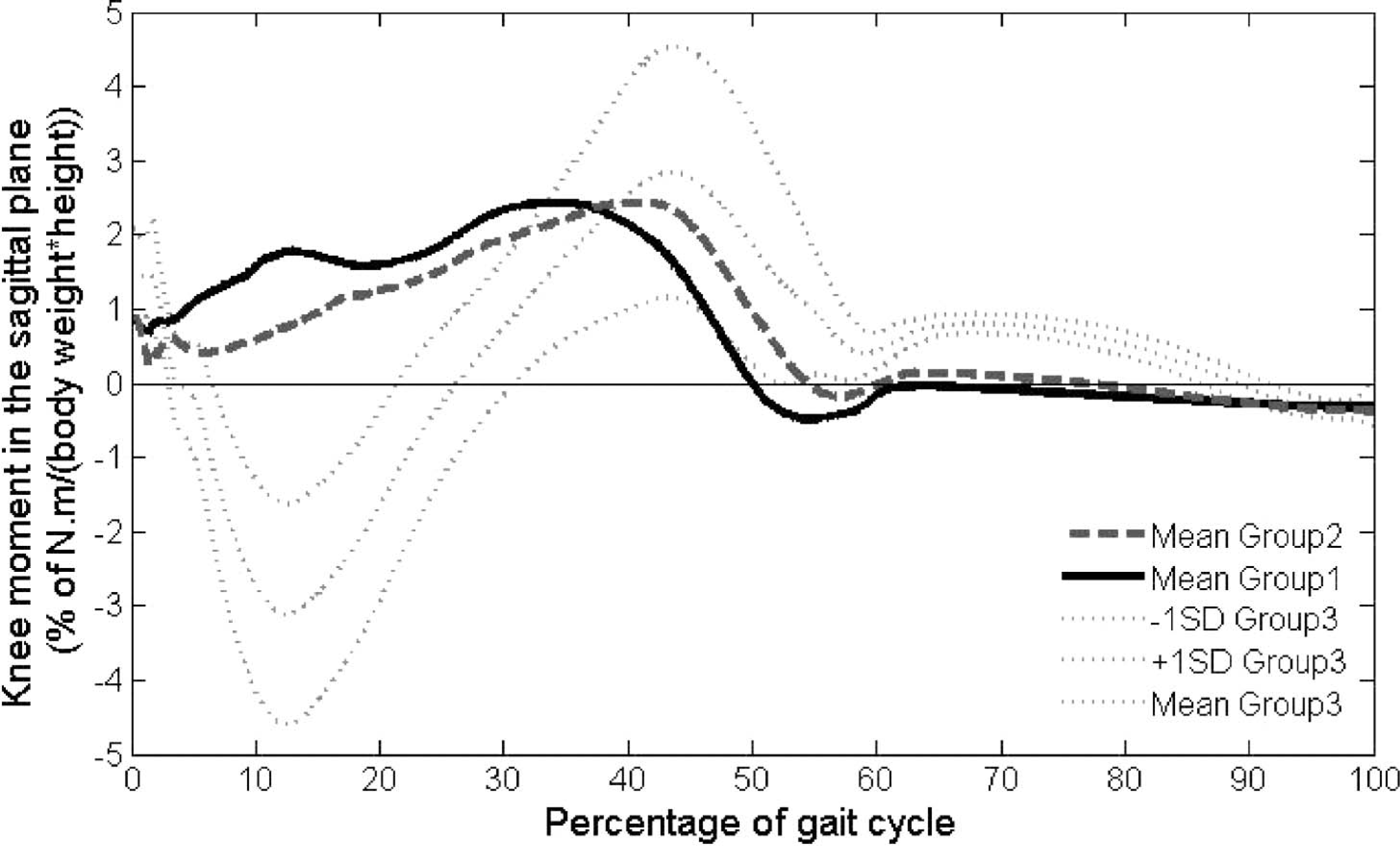
Knee moment in the sagittal plane: Comparison between the prosthetic sides of Group 1 and Group 2 and the left side of Group 3. Positive values indicate extension moment, and negative values indicate flexion moment.
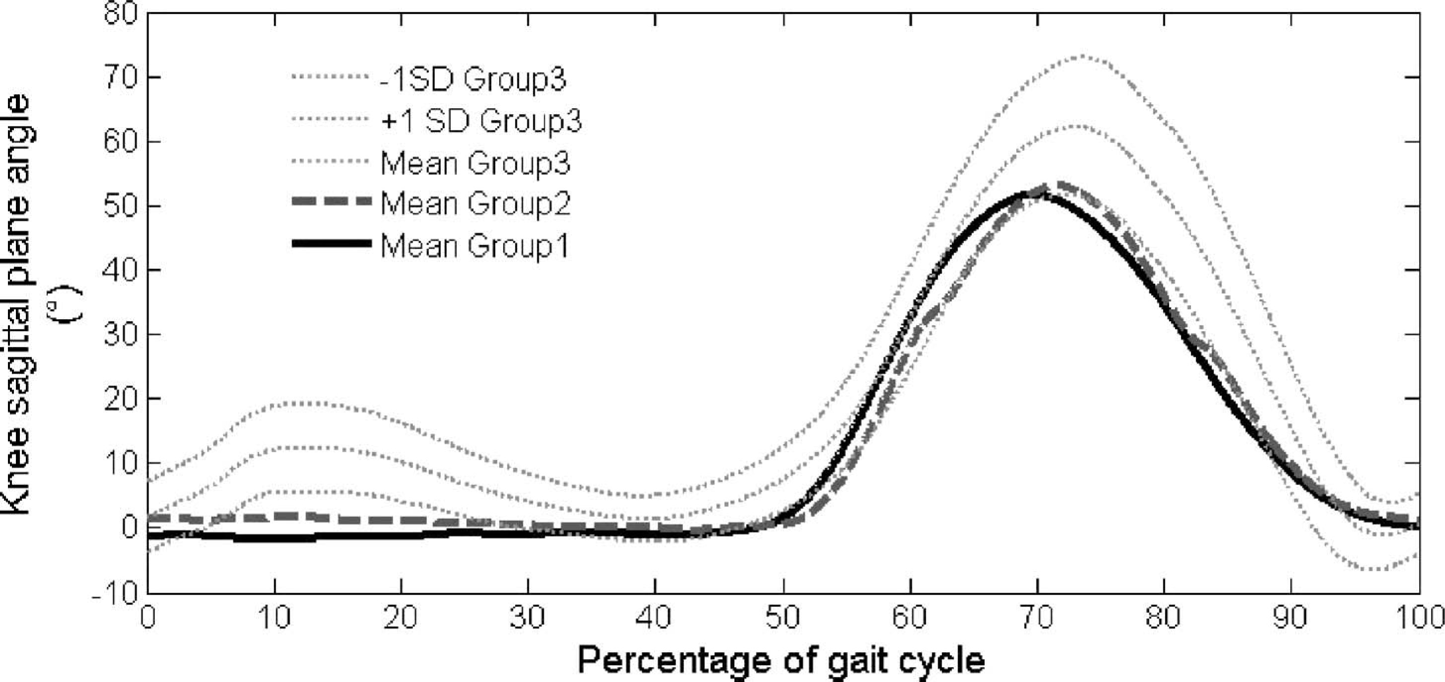
Knee flexion-extension: Comparison between the prosthetic sides of Group 1 and Group 2 and the left side of Group 3. Positive values indicate flexion moment, and negative values indicate extension moment.
To quantify and compare the knee sagittal plane moment of the prosthetic limb in Groups 1 and 2, the parameter KA was considered for each amputee. Within Group 2, KA was a third lower for the four participants using a hydraulic knee brake than it was for the fifth participant, who does not use one (6.73 ± 0.56 Nm/(%body weight ∗ height) for SNS system vs 20.4 Nm/(%body weight ∗ height) for S34). Comparison of the mean KA of Group 1 with that of the first four participants in Group 2 revealed that mean KA was significantly higher for the participants in Group 1 (16.7 ± 7.39 Nm/(%body weight ∗ height) for Group 2, compared with 6.73 ± 0.56 Nm/(%body weight ∗ height) for Group 1, p = 0.04).
The value of the moment at the knee in the sagittal plane depends both on the magnitude of the ground reaction force and on the position of the joint axis relative to the direction of the force. The vertical component of the ground reaction force did not significantly differ between the Groups 1 and 2 during stance (first maximum of the curve: Group 1 = 106.7 ± 7.7% body weight, Group 2 = 108.7 ± 8.9% body weight, p = 0.93, Figure 3). Therefore, the magnitude of the ground reaction force only depends on its anterior/posterior component (A/P reaction force).
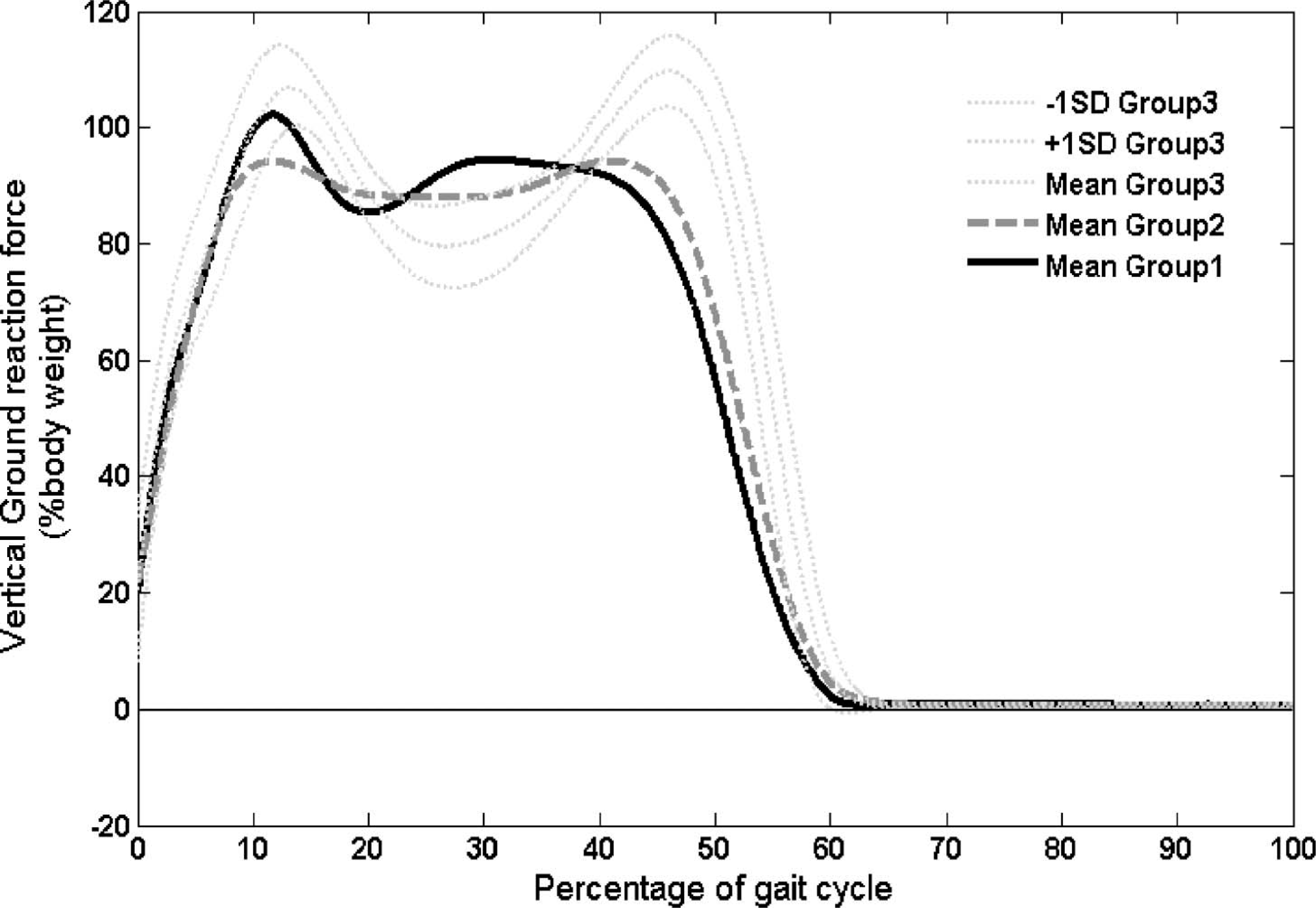
Vertical ground reaction force: Comparison between the prosthetic sides of Group 1 and Group 2 and the left side of Group 3.
A/P reaction force
This force component mainly depends on prosthetic-foot type. Since participants used their own feet (conventional feet in Group 1, dynamic feet with a carbon leaf system in Group 2—see Tables I and II), comparison between the two groups of amputees is limited.
Braking with the prosthetic limb (0–10% of the reference gait cycle)
At the beginning of the stance phase, the A/P reaction force (in the postero-anterior direction) corresponds to the braking effort. Considering the prosthetic side, the maximum absolute value of this effort (Br) is higher for Group 1 than for Group 2 (Br-Group 1 = –14.3 ± 4.4% body weight vs Br-Group 2 = –10.3 ± 3.8% body weight, p = 0.03—see Figure 4). It occurs nearly at the same time for the two groups (9.4% of the gait cycle for Group 1 vs 7.9% for Group 2, p = 0.43). Thus, from 0 to 10%, the magnitude of the global ground reaction force is higher for Group 1 than for Group 2.
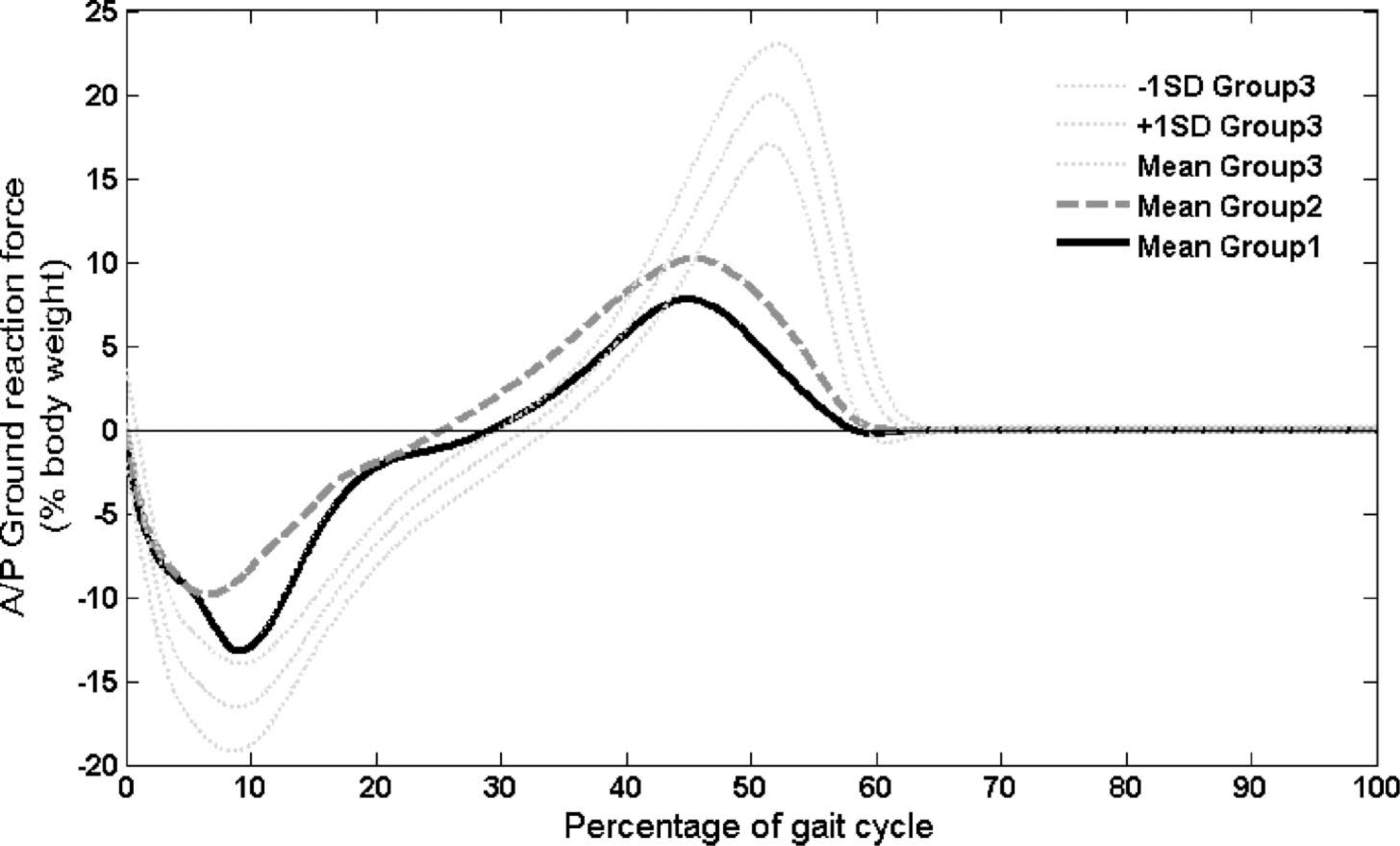
Anterior/posterior ground reaction force: Comparison between the prosthetic sides of Group 1 and Group 2 and the left side of Group 3.
Mid-stance: The loading and the single-limb stance on the prosthesis (10–40% of the reference gait cycle)
No significant differences are noticeable in the evolution of the anterior/posterior effort during this period between Group 1 and Group 2 (Figure 4).
A/P Propulsion with the prosthetic limb (40–60% of the reference gait cycle)
At the end of the stance, the A/P reaction force on the prosthetic limb corresponded to the way the prosthetic foot pushed on the ground. We noticed that the values of this force component at the end of the stance were, on average, very close in Groups 1 and 2 (Figure 4), even when the types of feet were very different. A/P ground reaction force was much lower in Groups 1 and 2 than in Group 3.
Gait analysis: During swing phase
Hip sagittal plane motion. No significant difference of hip sagittal plane motion was noticed between the three groups during the swing phase. Comparison of Group 1 and Group 2 (sound side) with Group 3 showed that the amplitude of hip flexion–extension was the same. Amplitude of hip flexion–extension was the same on both sound and prosthetic sides in Groups 1 and 2. The speed of flexion–extension of the hip was not related to the type of the prosthetic knee. However, it decreased with the stump length (Table III).
Speed of hip flexion: Relationship with the type of prosthetic knee and stump length
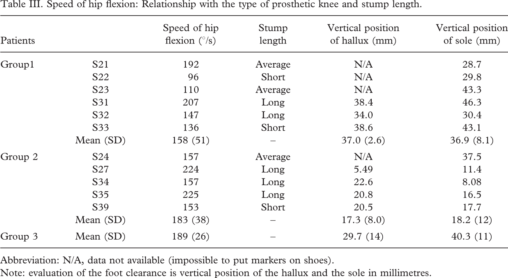
Abbreviation: N/A, data not available (impossible to put markers on shoes).
Note: evaluation of the foot clearance is vertical position of the hallux and the sole in millimetres.
Pendulum effect
Knee sagittal plane motion. Prosthetic knee joints flexed progressively to reach a maximum at 70% of the gait cycle. The amplitude of knee flexion-extension of Group 1 and Group 2 was lower than the one of Reference Group 3, but the difference was not significant. Prosthetic knee flexion was lower for Group 1 than for Group 2, but again this difference was not significant (p = 0.72, Figure 2).
Ankle sagittal plane motion. Ankle flexion–extension during swing phase varied between the groups. While the participants in Group 3 plantar-flexed the ankle, the participants in Group 2 had the ankle in neutral position, and the participants in Group 1 dorsi-flexed their ankle (significant difference between Groups 1 and 2, p = 0.045, Figure 5).
Ankle flexion-extension: Comparison between the prosthetic sides of Group 1 and Group 2 and the left side of Group 3. Positive values indicate dorsiflexion (flexion) moment, and negative values indicate plantar flexion (extension) moment.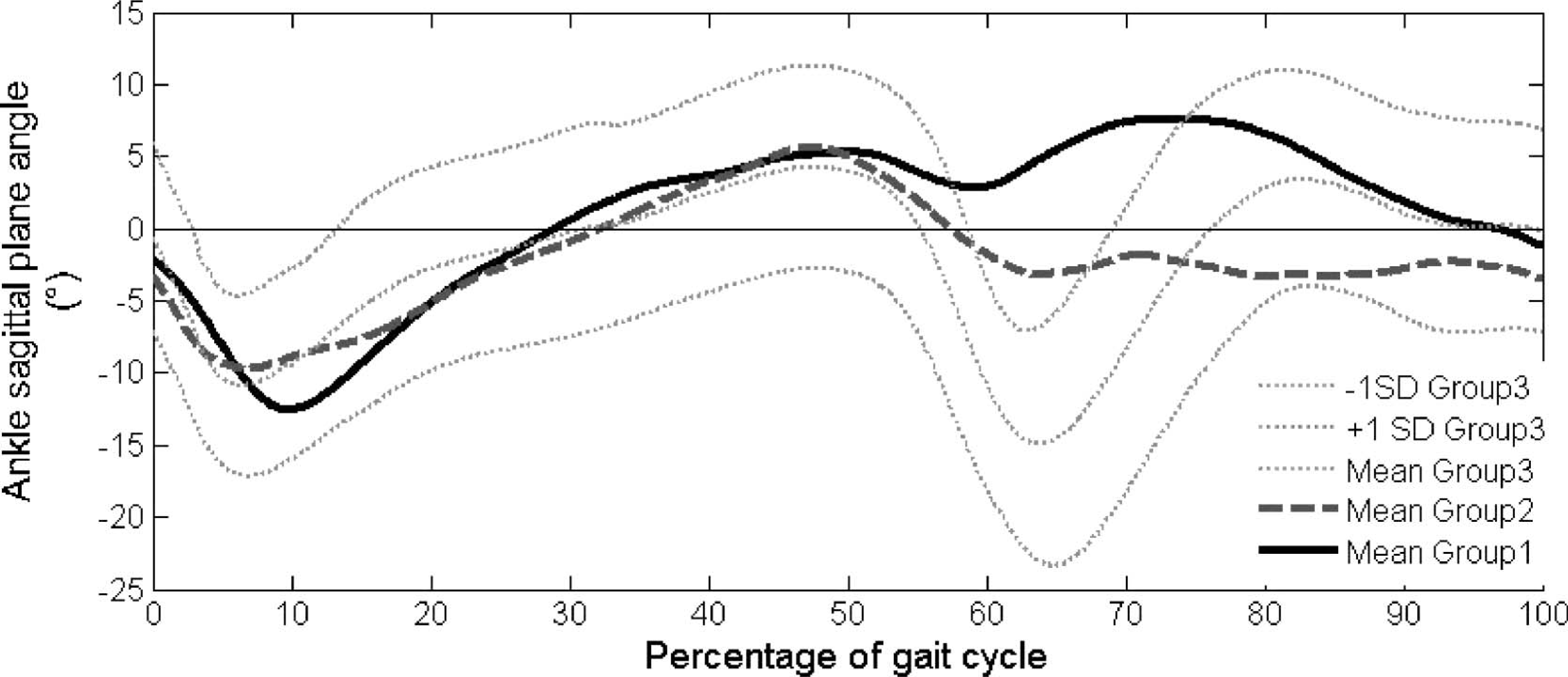
Pelvis lateral motion. The amplitude of the pelvis lateral motion was nearly the same in Groups 1 and 2. In contrast to the participants with normal gait, amputees displayed a contra-lateral bending during swing phase (Figure 6).
Pelvis medio-lateral tilt: Comparison between Group 1, Group 2, and Group 3. Positive values indicate contralateral moment, and negative values indicate ipsilateral moment.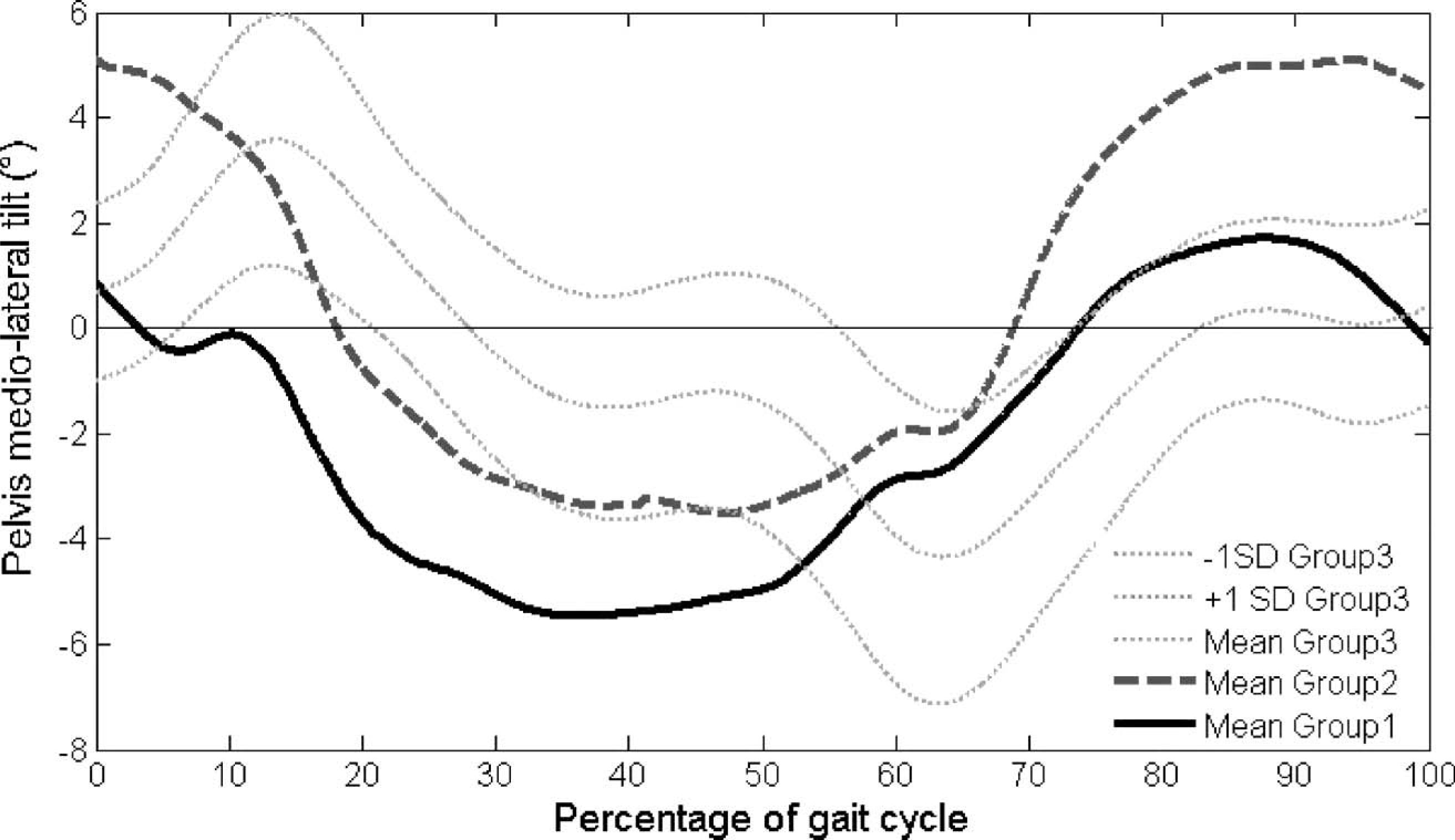
Foot clearance. The vertical position of the hallux of the participants in Group 1 was twice as high as that of the participants in Group 2 (Table IV). For participants in Group 1, the minimal vertical position of the hallux was slightly higher on the prosthetic side than on the sound side. The minimal position of the hallux was the same for the prosthetic side of Group 1 and Group 3 (Table IV, no statistical test made because of missing values). As expected, the results found for the vertical position of the sole were exactly the same.
End of swing phase: The slow down. At the end of the swing phase, the knee extension velocity did not significantly differ between Groups 1 and 2 (−324 ± 50°/s and −320 ± 31°/s, respectively, p = 0.9).
Comparison of the mean kinematic and kinetic parameters of Group 1, Group 2, and Group 3
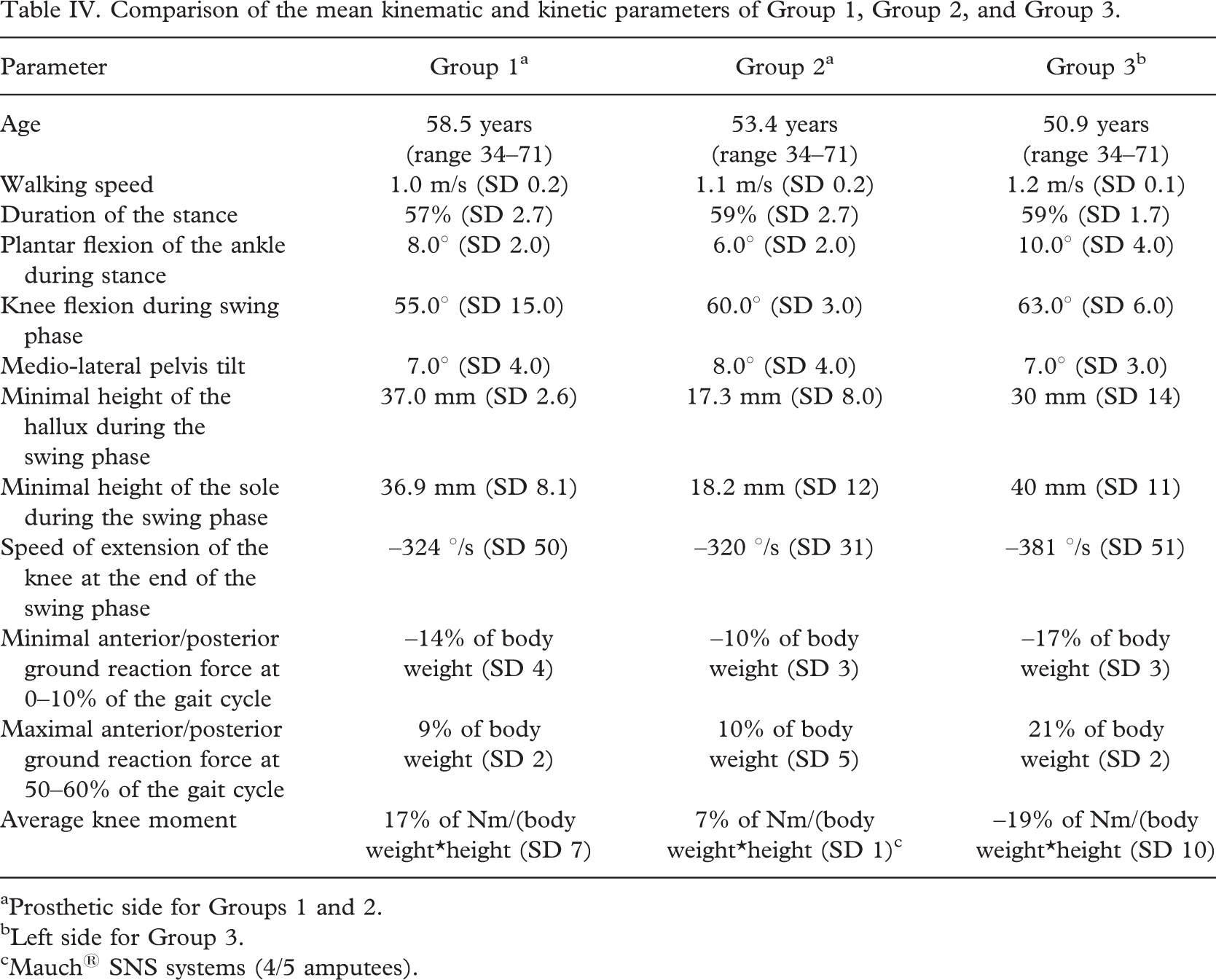
aProsthetic side for Groups 1 and 2.
bLeft side for Group 3.
cMauch® SNS systems (4/5 amputees).
Discussion
The purpose of this study was to study the gait patterns of trans-femoral amputees using two different single-axis knee joints with hydraulic swing-phase control, and especially to study the effect of a mechanical knee–ankle link. To evaluate specific functionalities of knee joints, the gait patterns of the two groups of amputees were also compared with those of individuals with normal gait.
Quantitative gait evaluation by means of 3-D motion analysis has previously been used to evaluate gait patterns of trans-femoral amputees, especially in regards to lower-limb kinematics (Blumentritt et al. 1998), and to quantify the effects of specific gait rehabilitation (Sjödahl et al. 2002). Using gait analysis to evaluate lower-limb prosthetic devices is more unusual. We followed a protocol that allowed a double comparison, first between two groups of amputees with different types of knee joints, and then between these groups and a reference group. This method enabled, in a single study, the evaluation of a specific device and the evaluation of functional gait patterns using each prosthetic system, compared with normal gait patterns. A questionnaire was used to propose an original clinical criterion by quantifying, and then ‘objectivizing’, the participants' activity levels.
Our study has several limits. Firstly, the number of participants was limited. Secondly, as participants were considered during their clinical gait-analysis examination, they were evaluated using their own prostheses. Although this is advantageous in that the participants were used to their prostheses, it does imply heterogeneity in the two amputee groups. Thirdly, our protocol was based on two distinct groups of patients, in contrast to the single-blind study by Boonstra et al. (1996). Thus, the comparison was somewhat biased, since inter-individual differences were not corrected.
However, several parameters showed that the comparison between the two groups of amputees is valid. A global analysis revealed that age and time since amputation were the approximately the same in Groups 1 and 2. Information extracted from the questionnaire revealed that gait velocity and activity level did not significantly differ between groups, either. There was a clear relationship between patient age and gait velocity: for all the traumatic amputees, the older the patients, the slower the gait. However, the relationship between patient age and activity was not so clear-cut: in Group 1, the older the patients, the lower the activity level was, but this was not true for Group 2.
The results of our kinematic and kinetic gait analyses are described for the successive phases of the gait cycle in order to refer to the functional demands that prosthetic knees are expected to provide.
In response to the need for security during stance, the knee moment in the sagittal plane makes the prosthetic joint remain in full extension during the stance on the prosthetic limb, contrary to the behaviour of people with normal gait. The value of the sagittal plane knee moment during weight bearing on the prosthesis (KA between 10% and 20% of the gait cycle) is significantly higher for the patients of Group 1 than for the patients of Group 2 using hydraulic stance systems. As expected, the patients wearing the Hydracadence® system needed to generate a more complete extension moment during stance to guarantee complete security, compared with the patients with the SNS system, since an additional hydraulic brake prevents uncontrolled flexion in these prostheses.
Kinetic analysis revealed that the vertical component of the ground reaction force as a fraction of body weight was similar for both groups of amputees during the whole stance. Differences in magnitude of the resultant force, therefore, depend only on the A/P component of the ground reaction force.
The results concerning the ground reaction force show that, at the beginning of stance (0–10% of the gait cycle), the maximal A/P ground reaction force, corresponding to the braking effort, occurred precisely when the plantar flexion of the Hydracadence® prosthetic ankle was maximal. Therefore, it is possible that the plantar flexion of the ankle allowed by the Hydracadence® system has a direct impact on the braking effort.
During the remaining time of stance (10–60% of the gait cycle), there was no significant difference between the two groups of amputees. It means that, for these trans-femoral amputees, the prosthetic components did not significantly change the kinetic patterns of the gait during this period.
Kinematic analysis enabled us to quantify the position of the axis of the joints relative to the direction of the force. The effect of the position of the knee flexion–extension axis has already been quantified for the very specific rotary hydraulic prosthetic knee mechanisms 3R80® (Blumentritt et al. 1998) but not for other prosthetic devices. Here, we show that the plantar flexion of the ankle of the Hydracadence® system during the first part of stance makes the prosthetic knee move forward later, so that knee joint axis remains far behind the direction of the ground reaction. This plantar flexion partly explains the increase of the knee-extension moment and assists stability during stance.
During swing phase, the prosthesis is activated by flexing the hip. According to the current results, this flexion does not depend on the prosthetic knee-joint type. This is consistent with Boonstra et al.'s (1996) study. Moreover, as Jaegers et al. (1995) have shown, hip flexion–extension depends on the stump length. We observed this tendency in our study, also.
Knee sagittal plane motion is nearly the same with the two types of knee joints. Boonstra et al. (1996) did not find the same results, comparing the Tehlin® knee and the 3R20® prosthetic joint: the flexion with the Tehlin® knee was 5° lower than with the 3R20®, but one patient was excluded from the group using the 3R20®. In our study, two patients of Group 1 (S23 and S32), did not flex their prosthetic knee as they should during swing phase (knee flexion lower than 20°). Indeed, participant S23 requested a prosthetic limb shorter than the sound leg to avoid lateral bending of the trunk, which generates a lower knee flexion. Participant S32 is accustomed to walking with a stick, but walked without an assistive device in the study. During the swing phase, he kept the prosthetic knee completely in extension and abducted the prosthetic leg to one side. We decided to keep them in the study to avoid reducing the statistical significance of the analysis. However, some gait patterns with the Hydracadence® knee-joint, especially during swing phase, may be modified by these patients, who walked poorly.
As expected, the original knee–ankle relationship of Hydracadence® prosthetic knees is noticeable during swing phase. The results show that the ankle begins to dorsi-flex when the knee flexes more than 20° (Figure 5). The minimal vertical position of the hallux during swing phase is higher for patients using the Hydracadence® prosthesis. If hip flexion is poor, the dorsi-flexion of the ankle would facilitate the foot clearance, but might not be sufficient, since the sole could drag on the floor. The minimal vertical position of the middle of the sole is also higher for Group 1 than in Group 2. Thus, foot clearance is facilitated for Group 1.
If foot clearance is facilitated for Group 1, no alteration of the pelvis tilt was noticed in this study. An explanation is the lack of proprioception, which probably leads amputees to elevate their pelvis even if this movement is not necessary. Specific re-education could solve this problem, and a gait trial on uneven ground might reveal differences between the two groups of amputees.
Finally, the speed of extension of the prosthetic knees during the deceleration did not differ between the two groups of amputees. Even though the swing-phase control systems were different, the hydraulic-damping properties were similar for the trans-femoral amputees considered.
Conclusions
This article reports on an objective kinematic and kinetic comparison of two different types of knee joints, with reference to normal gait. Clinical data, especially patients' activity and feelings, were added to the quantitative 3-D gait analysis by means of a questionnaire.
The number of patients was limited and the study contains several biasing factors. An extensive study should be carried out to confirm our results. Keeping in mind these remarks, our main findings were as follows:
the plantar flexion of the ankle after heel strike allowed by the Hydracadence® hydraulic system increases stability; the Hydracadence® knee joints have the same sagittal-plane motion as the other single-axis prosthetic knees with hydraulic swing-phase control systems; the Hydracadence® knee-joint system allows dorsi-flexion of the ankle during swing phase, which facilitates foot clearance; and no alteration of the kinematics of the pelvis is observed.
The present study succeeds in quantifying and comparing motions of different knee joints and their consequences on global gait parameters. Moreover, it relates kinematic and kinetic data to the activity evaluated thanks to a questionnaire. This type of protocol could help to determine which prosthetic knee fits individual patients best.
Footnotes
Acknowledgements
The authors wish to thank the patients in this study, and the prosthetists at the CERAH, D. Azoulay and C. Cazorla, for their help during the experiments, and Proteor, which supported this study.
Appendix I. Questionnaire completed during clinical exam: Questions about activity level
Appendix II. Calculation of activity level scores
Accommodation type: house =1 point, flat or retirement home = 0 points
If the accommodation type is a house:
Number of floors
Points
1
1
2
2
3
2
If the accommodation type is a flat or a retirement home with access by stairs:
Storey 0
Storey 1
Storey 2
Storey 3
Storey 4
Storey 5
Storey 6
1 floor
0
1
1
1
2
2
2
2 floors
1
2
2
2
2
2
2
3 floors
1
2
2
2
3
3
3
If the accommodation type is a flat or a retirement home with an access by lift: 0 point.
Working person = 1 point. Jobless or retired person = 0 point.
If the amputee works:
Need to walk at the job place (3 points):
Frequency
Points
Rarely
0
Sometimes
1
Quite often
2
Often
3
Usual means of transport to work (3 points):
Means of transport
<10 min
10–30 min
30 min to 1 h
>1 h
On foot
1
2
3
0
By public transport
0
1
2
3
By car
0
0
0
0
Activities cited by the amputee are classed according to the following item:
Leisure activity
Points
No leisure
0
Activity with no or few need to walk
1
Gardening, outdoor activities
2
Gait and sports with small displacements
3
Occasional practice of sports with running
4
Regular practice of sports with running
5
How often do you visit a local shop?
Never
Once a week
Twice or three time a week
Every day
0 points
1 point
2 points
3 points
How often do you go to the supermarket?
Never
Once a month
Twice or three time a month
Every week
0 points
1 point
2 points
3 points
Assistive device:
How often would you walk for more than 5 minutes, not including the above reasons?
Never
Once a week
Twice or three time a week
Every day
0 points
1 point
2 points
3 points