
Abstract
This article describes the procedure taken to modify trans-tibial shuttle lock release mechanisms to decrease standard reach requirements in a case of limited mobility secondary to morbid obesity. The participant was a middle-aged, morbidly obese client with bilateral trans-tibial amputations. The distomedial shuttle lock release buttons were modified to activate with a cable/Dacron pull strap located proximal/lateral. The outcome of the modification was determined by whether or not the client would be able to independently doff the prostheses, if the patient was satisfied with the prostheses and by the condition of the components at the three-month follow-up. The client was independently successful at doffing both prostheses following the modification procedure. The patient expressed satisfaction with operation of the release mechanism but cosmetic covering was an issue. Components were optimally functioning at the three month follow-up. It was concluded that this procedure is a viable option for relocating distomedial release lock buttons more proximally when reach is limited. The procedure is not indicated in every case as gadget tolerance, cosmesis and manufacturer warranty issues must be considered.
Background and purpose
Obesity is a national epidemic that is associated with chronic disease, decreased life expectancy, osteoarthritis, joint pain, decreased quality of life and impaired mobility (Campbell et al. 2002; Mokdad et al. 1999; Andersen et al. 2003; Fontaine and Bartlett 1998). It presents several unique challenges for affected patients and all involved healthcare team members. Prosthetic limitations are encountered even prior to fitting the obese client with amputation with an artificial limb. For example, several prosthetic feet manufacturers must design case-specific, customized feet once a certain weight limit is exceeded. This is a problem because component choice becomes increasingly limited, cost increases and functional outcomes may be compromised. In terms of other component issues, special, heavy-duty pylons, tube clamp adapters and bolts are usually also indicated in the presence of high body mass.
When obesity is among the list of comorbidities, choices of premium componentry are not always optional. The prosthetist is, in some cases, forced to use a particular component as it may be the only one available that satisfies the given mass requirements.
In terms of interface issues, there are no specific guidelines in terms of lamination lay-up for the obese client, but seasoned clinicians likely expect a heavier, thicker socket as the outcome. With regard to choice of socket/interface design, again, restrictions are encountered and problems result. For instance, Prosthetics-Orthotics Center, Northwestern University Medical School (2003) indicates, with regard to trans-tibial suspension, that supracondylar suspension is contraindicated with an obese thigh. In addition to suspension however, the supracondylar feature of an interface aids in limiting undesired interface rotation about the stump as well as providing stability in the frontal plane (Prosthetics-Orthotics Center, Northwestern University Medical School 2003). With consideration for functional issues, ADLs and IADLs, it is reasonable to expect that the obese client will experience difficulty donning and doffing liners, socks and ultimately, the entire prosthesis.
Following the fabrication and fitting of new, replacement bilateral prostheses for an obese client, the individual was unable to reach the traditionally positioned release button(s) to doff the prostheses. Increased abdominal mass approximating the thighs restricted forward bending of the trunk, which effectively decreased the ability for the hand to reach the shuttle lock release button(s) in their traditional location at the end of the stump. The purpose of this technical modification was to adapt the location of the locking mechanisms to a more accessible, proximal position due to restricted range of forward trunk mobility associated with obesity.
Methods
When this problem was discovered, the prostheses were ready for preliminary fitting and delivery. The client donned the limbs, test walked inside parallel bars and the prostheses were dynamically aligned. Socket adjustments were indicated. When asked to sit and doff the limbs, the client independently transferred to sitting but was unable to doff the prostheses due to limited reach. The client requested that the release be positioned more proximal and lateral. The prostheses were of the following design: Flexible interface (Bioelastic® thermoplastic)/Rigid frame (polypropylene thermoplastic), SPS locking mechanism (SPS-200-AK with button extender), utilized with Ohio Willow Wood®Alpha® liners and Ossur Vari-Flex® feet. The following steps were utilized to relocate the release mechanism:
The flexible interface and funnel were removed from the frame so the top of the lock mechanism would be accessible. A 0.3 cm hole was drilled through the release button to accommodate a 0.119 cm stainless steel cable that is routinely used to operate prosthetic elbow joints and the terminal devices of upper limb prostheses (Figure 1). A larger 1.5 cm hole was drilled in the frame distolaterally (Figure 2) to route cabling from the client's access laterally to the medial position of the release button. Distomedially, two additional holes were needed on either side of the original release exit. These 0.8 cm holes (Figure 1) were extended off the release hole and permitted the cabling to flow smoothly around the lock mechanism during cycling (Figure 3). The cable was then passed through the hole in the release button, into the frame along both sides of the lock mechanism. It was then directed back out of the frame, proximally along its lateral aspect. Cable exiting the lateral aspect of the prosthesis was passed through a cable housing and ferrule for several reasons including protection, unimpeded function, minimize damage to cosmetic covering and skin safety. The cable housing was terminated at mid-patella level where a cable housing anchor secured the assembly to the frame proximally. The cable was terminated into a hanger assembly which contained a 1.4 cm wide, 6.5 cm long, hand-friendly Dacron loop.
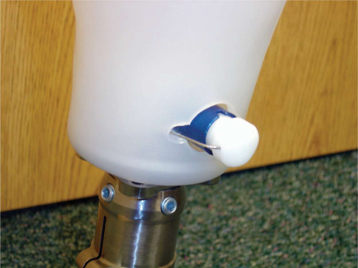
Distomedial view showing cable exiting the frame passing through the 0.3 cm hole in the release button. Additional 0.8 cm holes were required on either side of the release button to prevent the cable from kinking. (Please see colour online)
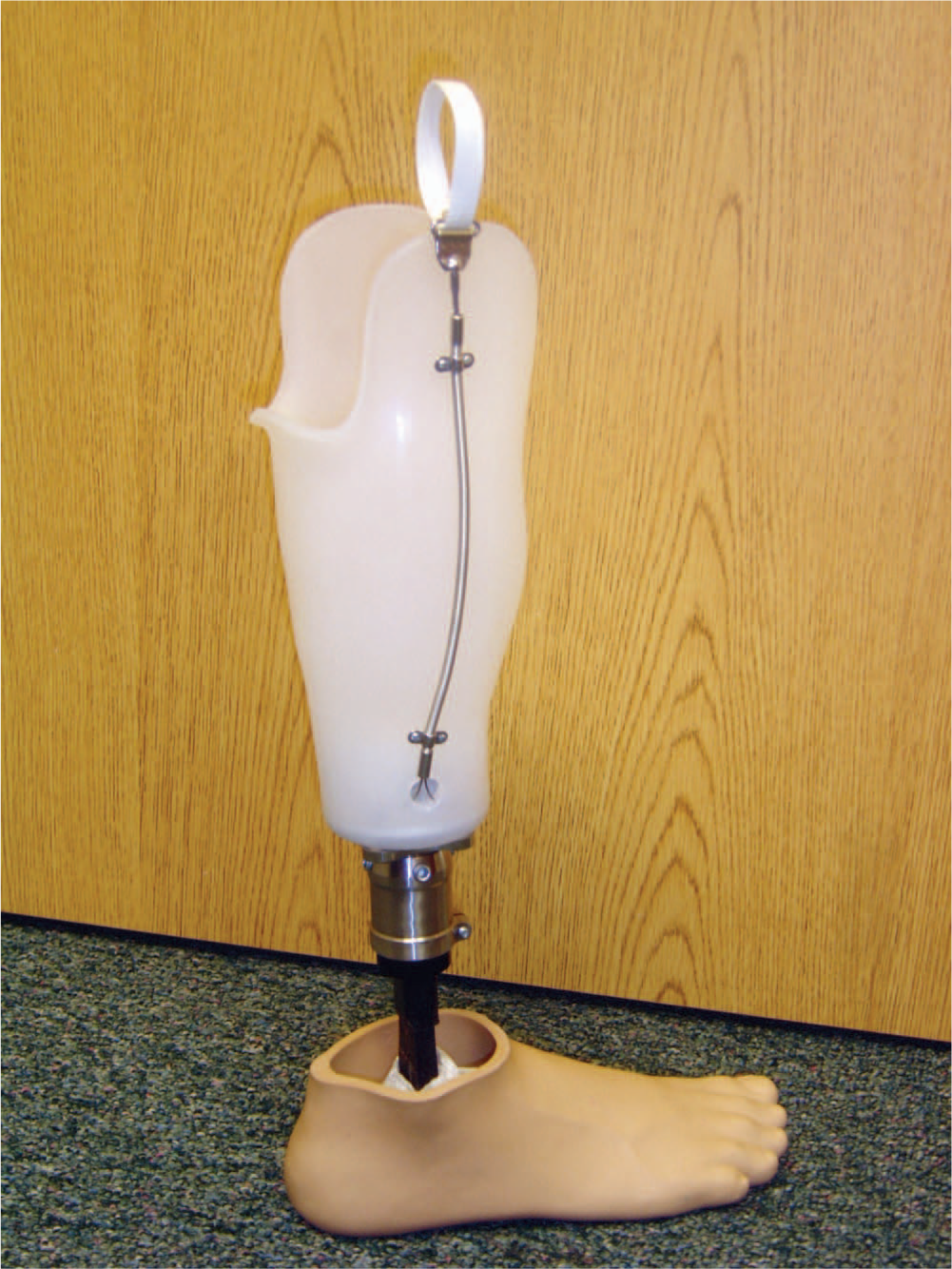
Finished mechanism prepared for foam covering. From proximal to distal the components are as follows; Dacron pull loop secured to a hanger assembly, cable housing protects 0.119 cm cabling that enters the socket frame distally through a 1.5 cm hole. (Please see colour online)
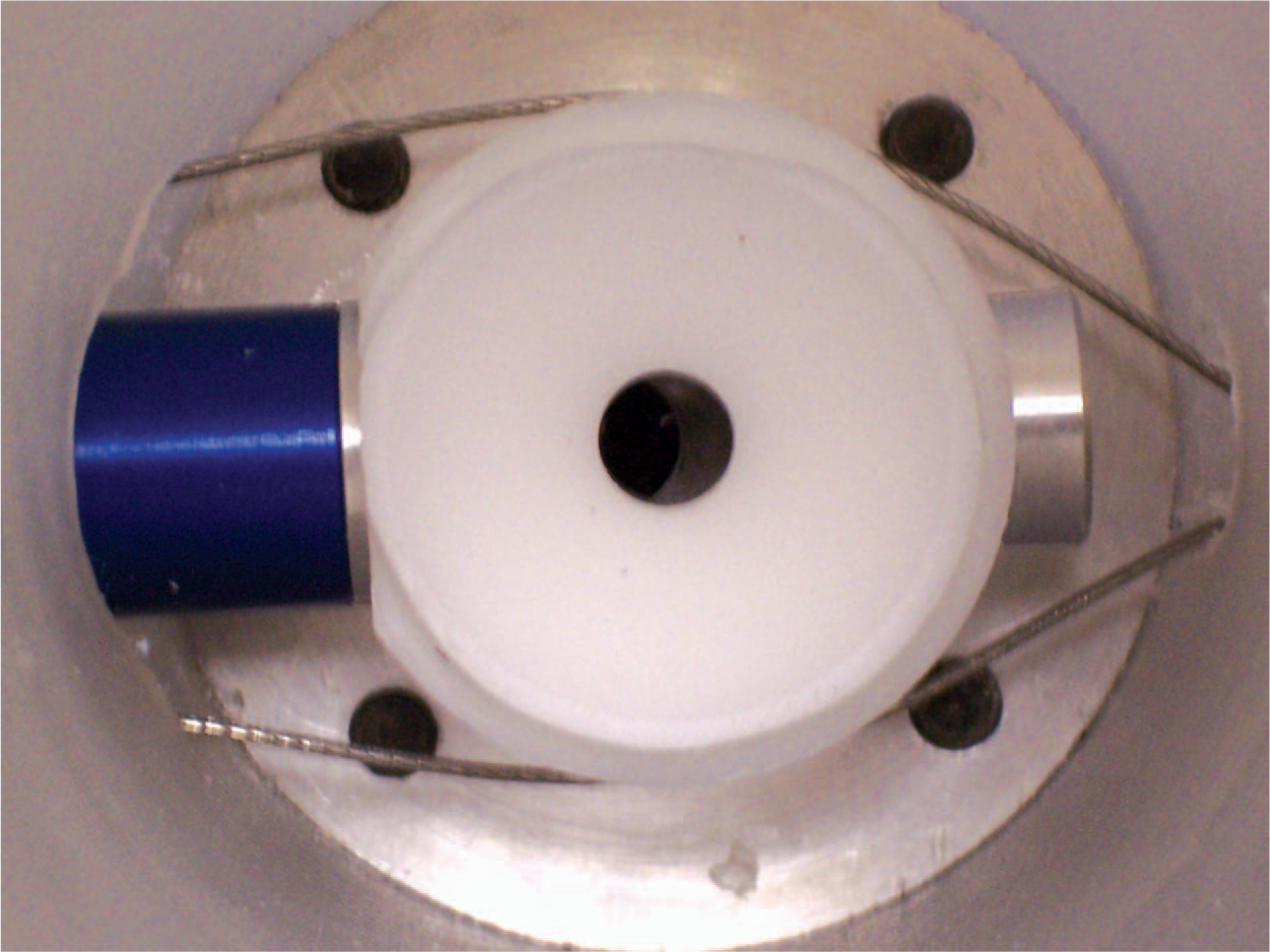
Transverse view (from superior to inferior) showing cabling entering the frame laterally (right) passing smoothly around the lock mechanism on its way out of the frame medially (left) where it passes through the release button. Once through the release button, the cable re-enters the frame, passes again by the lock, and finally, exits the frame. Once out of the frame, it travels in the housing where it is crimped into the hanger with the originating end. (Please see colour online)
When the lanyard is pulled, the release button is depressed in the usual fashion. In this case, approximately 32 cm of reach were eliminated. Following modification, the client was able to independently doff both prostheses. Cosmetic finishing was uniquely challenging due to the need for the lanyard to penetrate the cosmetic, pull-up skin. Long term (approximately three months), this created a problematic, chronic tear point about the necessary cable exit hole in the cosmetic skin.
Discussion and conclusions
This modification was undertaken partially due to the need to continue utilizing pin locking suspension with gel liners, as other forms of suspension were either deemed contraindicated, unsatisfactory or too difficult to independently manage in this case. Functionally, the procedure achieved its intended purpose of restoring independent doffing in the presence of markedly reduced reaching ability. In terms of cosmetic covering, it should again be pointed out that the external cabling accessories will quite likely prematurely damage any cover. Gadget tolerance was not problematic here but may be an issue in some cases.
It should again be pointed out that in order to route the cabling system from lateral to medial, a significant hole is necessary distolaterally. Thus holes are present medially and laterally and the very reason for the modification was for limited reach associated with obesity. This requires the practitioner to compare the risks of decreasing socket strength against the benefits of increasing independence with doffing. In this example, a 1.5 cm hole was used to permit the cabling to travel smoothly and freely around the locking mechanism. The 1.5 cm hole diameter was experimentally derived through trial and error. The starting point was a 0.5 cm diameter hole, forcing the cables through abrupt direction changes ultimately causing operational problems. The hole size was then systematically increased until operation was satisfactory. In this case, despite high body mass, there was no indication of ambulation over-stressing the thermoplastic (polypropylene) socket frame that could lead to potential socket failure due to the additional hole. If this became evident, a laminated socket with distal reinforcement would have been the next intervention.
This modification was additionally performed without consultation with the locking component's manufacturer and would most likely void the component's warranty. This procedure is not advised in every case and should likely only be utilized in very extreme circumstances such as this one. Other cases that might warrant further investigation of a similar modification include cases where the hands themselves are incapable of very fine motor control sufficient to activate the lock's release button or other situations where restricted range of motion prohibits reaching the release mechanism. The authors of this work advise carrying out a risk assessment comparing risk against benefit in addition to consultation with component manufacturers prior to undertaking such modifications to first rule in or out manufacturer recommended modifications that may already exist.
Footnotes
Acknowledgements
Preparation of this manuscript was funded in part by the U.S. Department of Education, Rehabilitation Services Administration Award # H235J050020 “Demonstration Project on Prosthetics and Orthotics”.