
Abstract
Monolimb refers to a kind of trans-tibial prostheses with the socket and shank moulded into one piece of thermoplastic material. If properly designed, the shank of a monolimb can deflect which may compensate for the lost ankle plantarflexion and dorsiflexion to some extent. However, provision of shank flexibility is usually accompanied by reduced structural strength of the entire prosthesis. In the recent work using finite element analysis and the Taguchi method, the dimensions of the shank for the monolimb were derived which aimed at giving high shank flexibility and reasonable strength to resist static load. Yet, fatigue testing has not been performed. Fatigue failure may happen when a relatively low level of load is applied repeatedly. This study aimed to document the fatigue life of two flexible-shank monolimbs, by applying cyclic force of 800 N at the forefoot region for 500,000 cycles. Results showed that the design of the foot bolt adaptor played an important role in the structural integrity of the monolimb. One monolimb completed the fatigue test of 500,000 cycles without visual material yield, but with 3.8° change in dorsiflexion angle when the load was removed.
Introduction
There are at least 3 million people globally who have had amputations performed (Murdoch 1990). Many involve the lower limb at the trans-tibial level (Smith et al. 2004; Murdoch and Wilson 1996; Wilson 1989). It is estimated that the number of people who receive lower limb amputations is on the rise, because of the longer survival rates. Lower limb amputation is no longer to be considered as purely the removal of a body part, but rather as a reconstructive procedure to restore walking function. Prosthetic replacement is one of the most significant rehabilitation programmes.
A high-quality lower-limb prosthesis can restore the locomotor function of the lost limb, and is believed to boost the functional status, self body-image as well as general health of patients with amputations performed. The quality of a lower-limb prosthesis refers mainly to the level of comfort, walking ability and durability that is provided (Legro and Reiber 1998; Legro et al. 1999). Previous studies suggested that there is scope for further improvement in the quality of lower limb prostheses, since stump pain, gait deviation and prosthetic structural failure are not uncommon. In the past two decades, new designs such as dynamic elastic response (DER) prosthetic feet have been brought to the market, aiming to bring amputees better comfort and gait efficiency while at the same time providing enough structural strength to support the whole body weight. These up-market prosthetic feet provide flexibility at the keel/shank to compensate for the lost dorsiflexion and plantarflexion motions at the ankle joint. As reviewed by Hafner et al. (2002), previous research suggested that many amputees subjectively prefer DER prosthetic feet to conventional SACH feet for normal and fast walking (Alaranta et al. 1991; Crandall and Anderson 1999; Gard and Konz 2003; MacFarlane et al. 1991), and the practical advantages have been supported by some objective biomechanical analyses (Nielsen et al. 1989; Power et al. 1994; Barr et al. 1992). Due to the high cost, however, those advanced prosthetic designs are not accessible to the majority of the amputees.
A “Monolimb” prosthesis using a conventional solid-ankle-cushioned-heel (SACH) foot perhaps is an alternative to DER prosthetic feet, providing elastic response of the shank (Valenti 1991), while at the same time lowering the total prosthetic weight and cost. Monolimb refers to a kind of trans-tibial prosthesis having the socket and the shank moulded into one piece of thermoplastic material. Different names have been used for this kind of prosthesis, including endoflex (Valenti 1991), total thermoplastic prosthesis (Rothschild et al. 1991), and ultra-light prosthesis (Reed et al. 1979; Wilson and Stills 1976). The shank, made of flexible thermoplastics, can deform leading to some dorsiflexion and plantarflexion motions of the prosthetic foot. By proper use of material and structural design, the shank deformability can be adjusted to mimic natural ankle joint motions.
Several papers have reported positive feedback from amputees using flexible shank prostheses, which included perceived improvement in comfort and gait efficiency (Beck et al. 2001; Coleman et al. 2001, Valenti 1991). It was suggested that a flexible shank monolimb tended to reduce prosthetic socket-stump interface stress (Lee et al. 2004), which might explain the improved comfort as perceived by the patients. Structural strength is one major concern related to the use of monolimbs. In recent work, the statistic-based Taguchi method and finite element analysis were used to optimize the shank design of monolimbs giving appropriate shank flexibility and reasonable strength to withstand static loading (Lee and Zhang 2005). Gait analysis suggested that the optimized monolimb may have similar function to the DER feet (Lee et al. in press). However, it is concerned that fatigue failure of monolimbs may happen when the load is repeatedly applied. This study served as a part of a series of studies in designing and testing monolimbs. The aim of this study is to investigate the changes in structural behaviour of monolimbs under repeated loadings.
Method
Fabrication of monolimbs
Two monolimbs of different adaptor designs were fabricated for the fatigue test. The socket and alignment of the monolimbs were made according to one right-sided trans-tibial amputee. Before fabricating the monolimbs, a temporary endoskeletal prosthesis with a metal pylon and alignment adjustable adaptors (Figure 1a) was made. A clinical trial was arranged for the amputee to optimize the socket fit and alignment. The socket shape as well as the alignment of the temporary prosthesis was then duplicated to the monolimb. The temporary prosthesis was put into a duplication jig as shown in Figure 1a. With the socket being held securely in the duplication jig, the adaptors and pylon components were removed and a hole was cut at the distal end of the socket. A long mandrel was put in place following the alignment of the temporary prosthesis (Figure 1b). The temporary socket was then filled with plaster solution. After the plaster set, the temporary socket was cut and removed from the plaster. A foot bolt adaptor was attached distal to the mandrel. A polypropylene homopolymer sheet was heated and vacuum formed over the entire structure of the foot adaptor, stump and pylon mould (Figure 2). The plaster and the long mandrel were removed as the thermoplastic sheet hardened. A Kingsley SACH foot was screwed to the foot bolt adaptor. Proper trimming and finishing were performed. Using socket duplication foam (Otto Bock Inc.) and an alignment duplication device, the second monolimb was fabricated with the identical alignment socket and shank shape, but with two different foot bolt adaptor designs as shown in Figure 3.
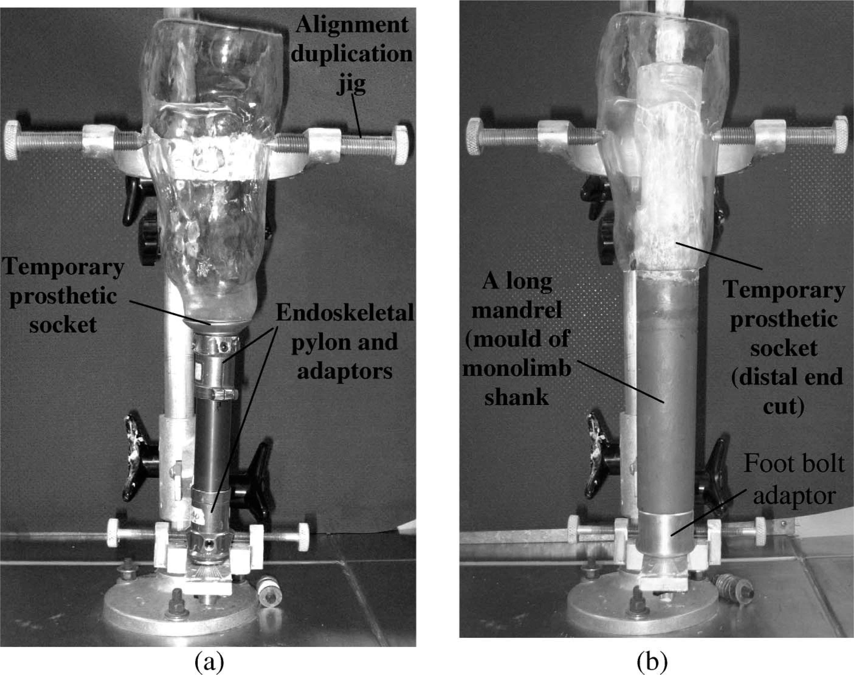
(a) A temporary prosthesis is put into an alignment duplication jig. (b) A long mandrel is put in place following the alignment of the temporary prosthesis.
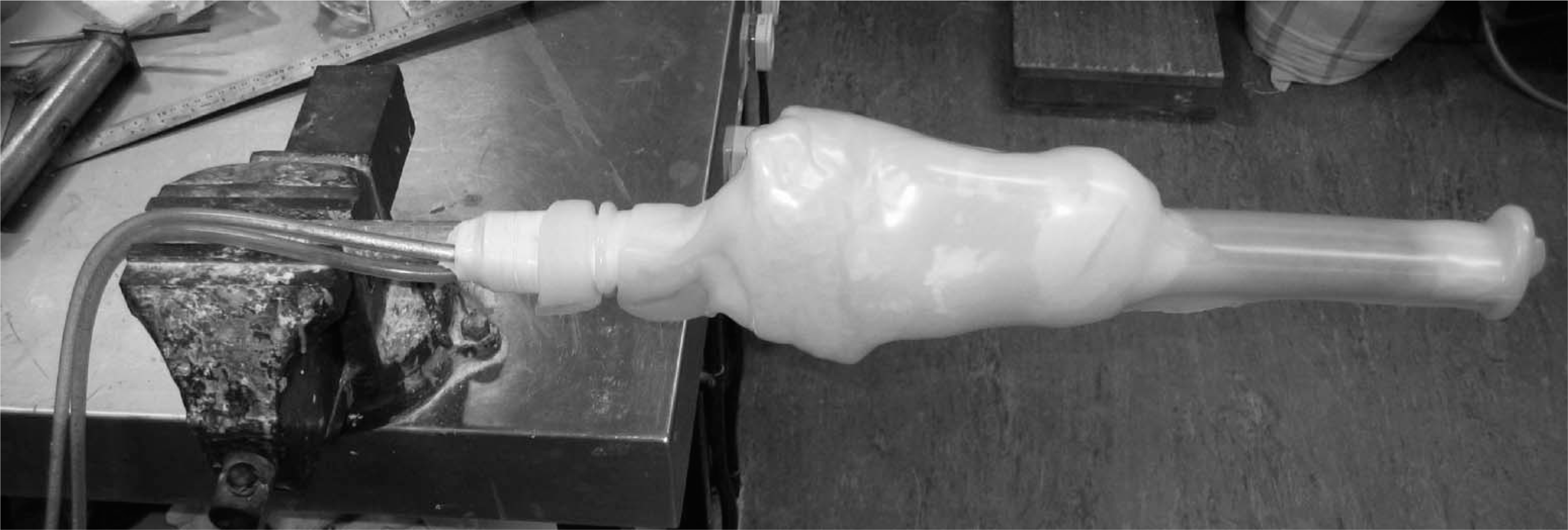
A thermoplastic material sheet is heated and vacuum formed over the entire structure of the foot adaptor, residual limb and pylon mould.
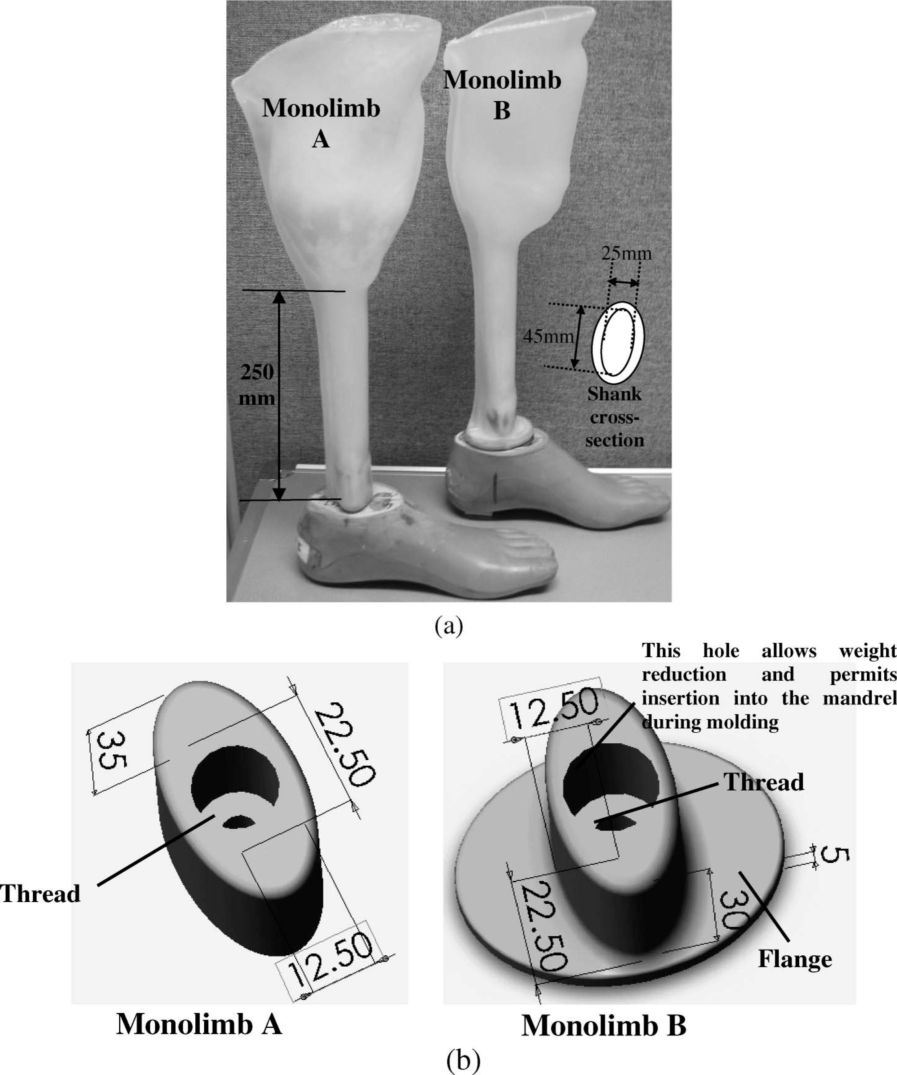
(a) The two monolimb designs, having the same alignment and shank shape but differing in (b) the shapes of the adaptors.
Fatigue test of monolimbs
Fatigue testing of the monolimbs was performed using an MTS material testing machine (Model 858 Mini Bionix, MTS System Corporation, Minnesota). As shown in Figure 4, the monolimb was offset by an extension aluminium block and mounted to the actuator linked to a linear voltage displacement transducer (LVDT) which shows the vertical displacement of the actuator. The monolimb was loaded against a 20° rigid tilting block at the forefoot, which was related to the heel-off phase of the gait. The tilting block was attached securely to the load cell. The prosthetic foot was aligned such that there was no toe-in and toe-out, and the long axes of the extension block and the tilting block were aligned with that of the prosthetic foot. At the beginning, a 50 N test force was applied to the forefoot and the original actuator position was recorded by the LVDT. Next, a sinusoidal waveform of pulsating force oscillating between 800 N and 50 N at a frequency of 1 Hz was applied to the forefoot until 500,000 cycles was reached or the test monolimb structurally failed. The test was interrupted at the end of the successful 0, 5000, 10,000, 20,000, 50,000, 100,000, 200,000, and 500,000 cycles, and (i) a static load of 800 N was applied to the monolimb to detect changes in the structural stiffness of the monolimb due to the fatigue test; (ii) the new actuator position was recorded upon application of 50 N, which was then subtracted from the original actuator reading to give the permanent deformation of the prosthesis; and (iii) an approximate assessment of the dorsiflexion angle change was made, by calculating tan−1 (dc/140), where dc is the new actuator position minus the original actuator position at the load level of 50 N, and 140 mm was the horizontal distance between the centre of the foot bolt and the region of contact between the prosthetic foot and the tilting block. The angle changes considered both the deflection of the shank and compression of the sole.
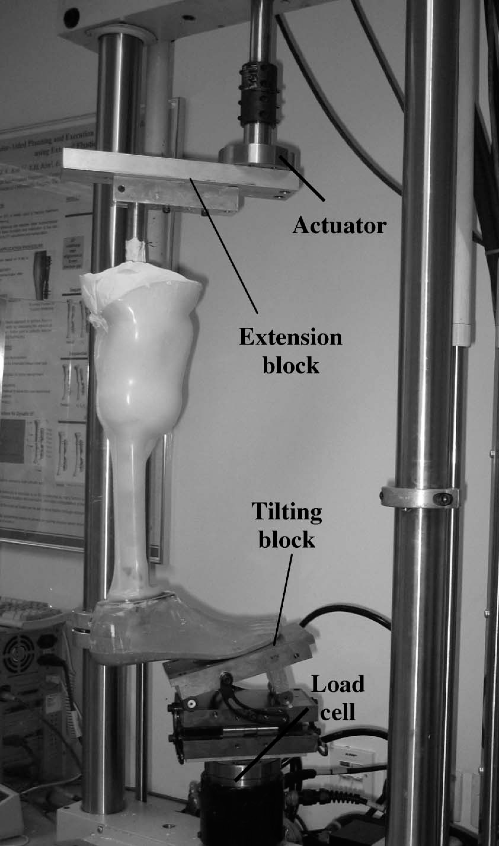
Test set-up of the fatigue test.
Fatigue test was performed on two monolimbs as shown in Figure 3a. The two monolimbs were identical, except for different foot bolt adaptor designs. The dimension of the elliptical shank (anteroposterior dimension 25 mm, medialateral dimension 45 mm) was chosen according to the design optimization process (Lee et al. in press) for trans-tibial amputees of up to 80 kg body mass. As shown in Figure 3b, the Monolimb A used an elliptical-shape foot clamp adaptor; whilst Monolimb B used a similar adaptor but with a flange distally. The addition of a flange aimed to: (i) reduce the pressure at the junction between the shank distal end and the top surface of the wooden keel; and (ii) hold the adaptor inside the shank better.
Results
The Monolimb A, using an elliptical foot bolt adaptor, failed the fatigue test as structural failure occurred before reaching 20,000 cycles. The anterior aspect of the distal end of the shank created a hole on the top surface of the wooden keel of the SACH foot (Figure 5). With the hole, the foot bolt adaptor tended to tilt against the top surface of the keel upon application of loads. At the end, the screw broke into two separating the prosthetic foot and the shank portion of the monolimb before completing 20,000 cycles. A better adaptor design spreading and reducing the pressure at the junction between the shank distal end and the top surface of the wooden keel is desired.
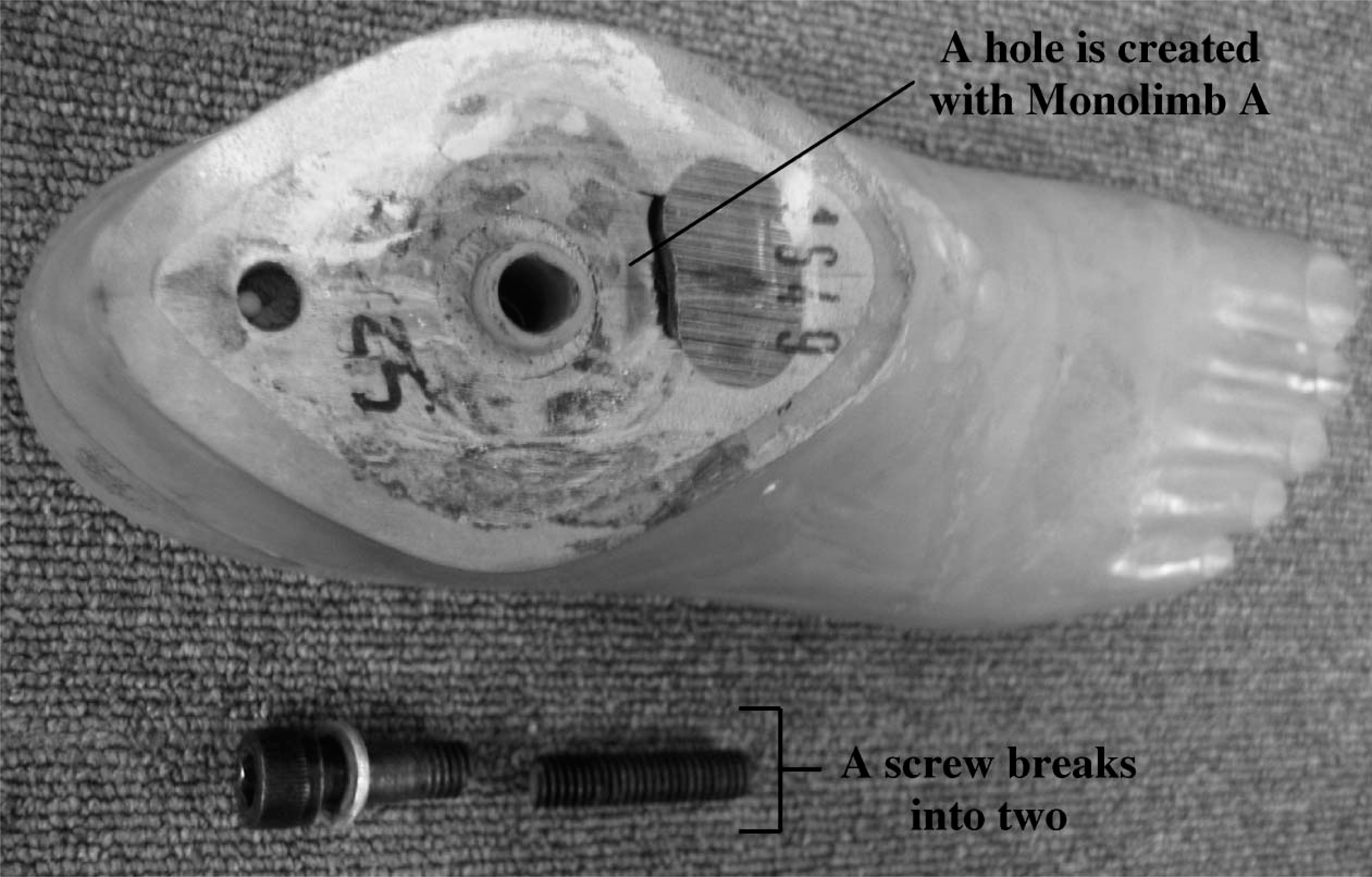
The anterior aspect of the distal end of the shank creates a hole on the top surface of the wooden keel and before completing 20,000 cycles the screw fractures and leaves no connection between the foot and the shank.
The Monolimb B used a similar adaptor but with a flange added distally (Figure 3b). The flange had minimal effects on the stiffness of the entire prosthesis upon static loading, as shown in Figure 6. However, the addition of a flange allowed the monolimb to complete the fatigue test, without visual necking of the thermoplastic and breakdown of the keel of the SACH foot. Figure 7a shows the permanent deformations and approximate dorsiflexion angle changes at 50 N of load after successful completion of 0, 5,000, 10,000, 20,000, 50,000, 100,000, 200,000, and 500,000 cycles. A 3.8° change in dorsiflexion due to permanent deformation of the prosthesis was estimated after 500,000 cycles of load. Figure 7b shows two loading-unloading curves at 0 and 500,000 cycles, respectively. The figure demonstrates: (i) both curves showed the characteristic that the unloading portion of the curve did not follow the loading one (hysteresis); (ii) each single loading-unloading curve showed minimal permanent deformation as the actuator tended to end at the starting position; and; (iii) after 500,000 cycles of loads a total of 8.6 mm permanent deformation was read by the LVDT at the load level of 50 N. However, as the monolimb became stiffer after repeated loading, upon application of 800 N the difference in LVDT reading between 0 and 500,000 cycles was reduced to 4.8 mm. In addition, a tendency of increased overall stiffness was observed as the number of cycles increased. Figure 8 shows the stiffness changes of the prosthesis along the fatigue test at 0, 5,000, 20,000, 100,000, and 500,000 cycles. The increased stiffness is believed to be related to the compression of the polyurethane sole of the prosthetic foot.
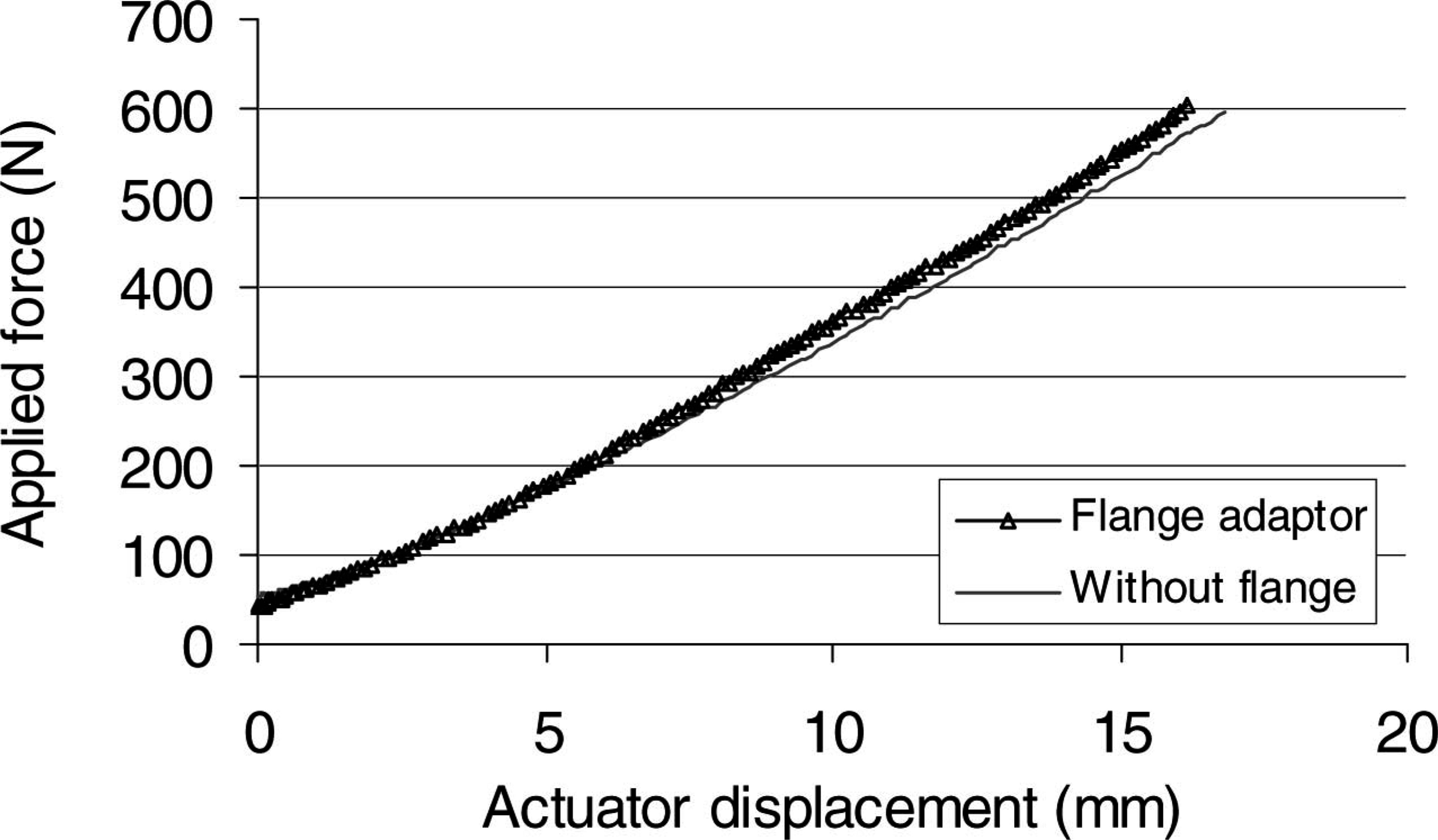
This graph of load vs. displacement shows that the flange had little effects on the stiffness of the monolimb.
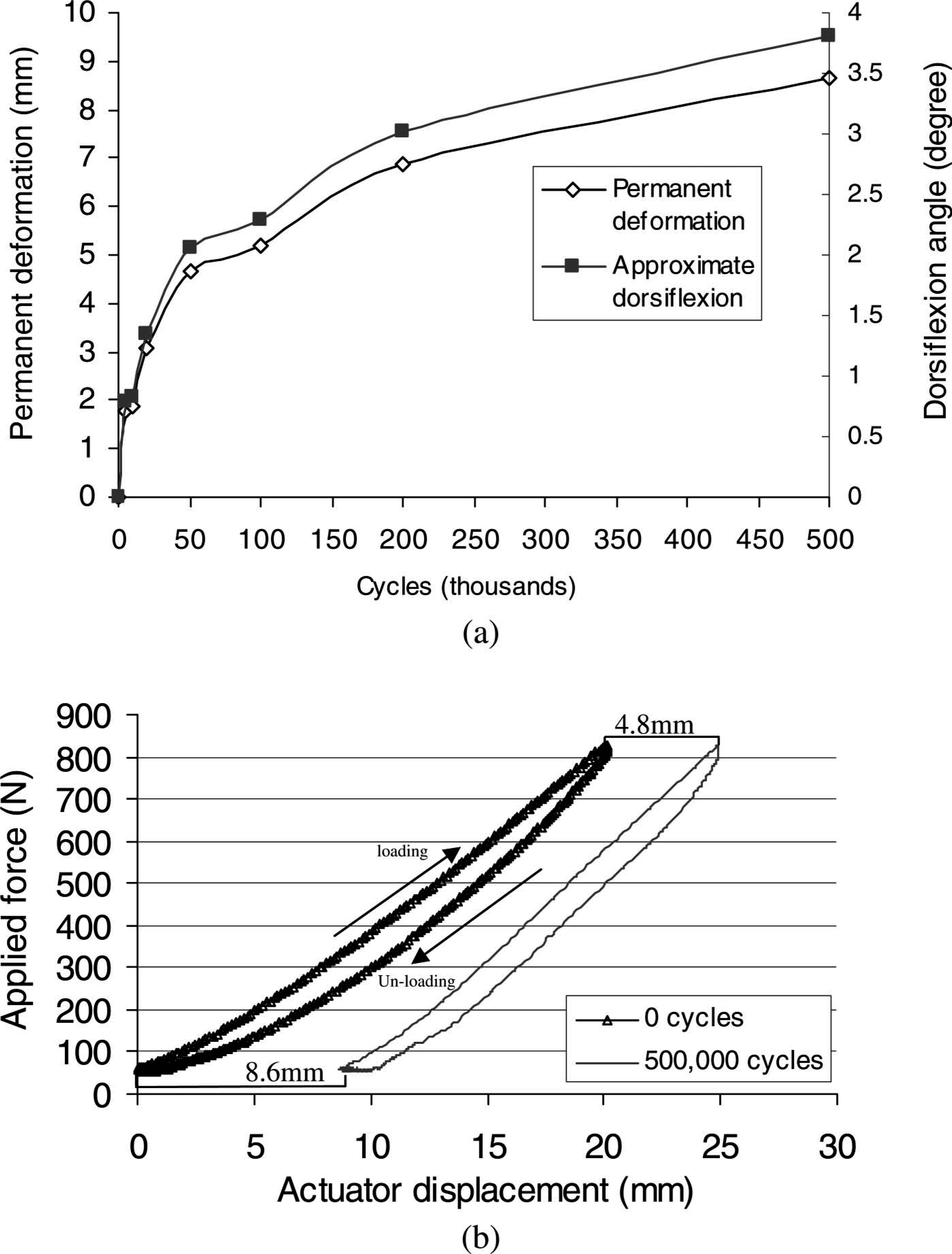
(a) The permanent deformation and approximate dorsiflexion angle changes at 50 N of load for Monolimb Design B during the fatigue test. (b) The loading and unloading curves at 0 and 500,000 cycles respectively.
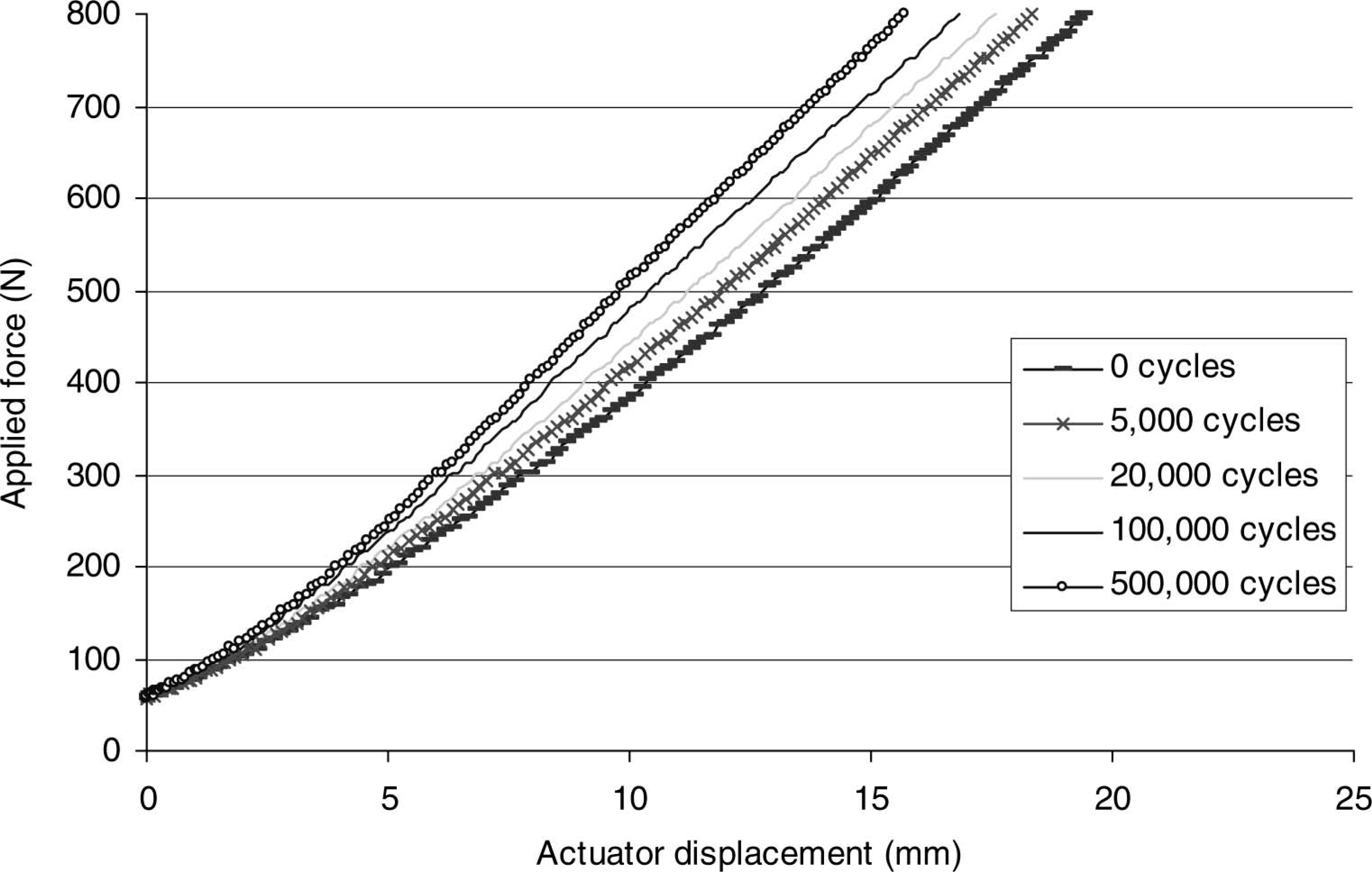
The gradients of the curves show the changes in stiffness of the monolimb with the number of load cycles applied.
Discussion
The loss of active motion of the ankle joint was suggested to be the major cause of gait deviation and increased energy consumption during walking (Bowker and Kazim 1989). Provision of active ankle motion at a lower-limb prosthesis by the attachment of artificial muscles is very difficult as it requires accurate timing and intensity of different artificial muscle contractions during activity. Passive plantarflexion and dorsiflexion can be brought about by controlled deformation at part of the prosthesis during early stance. A properly designed monolimb shank has the potential to provide the required deflection. The amount of deflection of the prosthetic components upon load application can be studied in computational models, experimental structural tests and gait analysis.
It is believed that some flexibility provided by the monolimb shank is beneficial to gait. However, provision of flexibility is usually a compromise with reduced structural strength. Structural tests are needed to determine the strength and fatigue life of the prosthesis. Previous studies applied loads according to consensus reached at the International Society for Prosthetics and Orthotics (1978) or test methods laid out in the International Standard ISO 10328:1996 (Current et al. 1999; Coombes and MacCoughlan 1988; Goh et al. 2002; Neo et al. 2000). The Compliance International Standards ensures the structural integrity on loading. However, it has been commented that the load levels set by the standards are too severe (Wevers and Durance 1987) that many prosthetic components failed to comply with the standards (Coombes and MacCoughlan 1988; Current et al. 1999). In addition to the load level, the strict restriction on the allowable deformation makes it difficult for plastic prostheses to comply with the standard. Some previous structural tests applied force based on the body weight of the subject that the prosthesis was specially designed for (Toh et al. 1993; Wevers and Durance 1987). Monolimbs produced the largest degree of deformation at the heel off phase of the gait (Lee et al. 2004). In this study, cyclic loadings were applied to the forefoot which oscillated between 800 N and 50 N up to 500,000 cycles. The 500,000 loading cycles corresponds to approximately one-year usage of the prosthesis for an amputee walking at about 1,300 steps on the prosthetic side per day. The socket-shank structure of the monolimb was attached to a SACH foot during the fatigue test, which allowed the study of the structural change at the interface between the wooden keel and the distal shank end. Results showed that the Monolimb B using a flanged foot clamp adaptor passed the fatigue test without visual yield of the thermoplastic material.
An approximate 3.8° change in dorsiflexion angle (8.6 mm permanent deformation) is noted at the load level of 50 N, after completion of 500,000 cycles of loads. Permanent deformation can occur at the rubber sole of the Kingsley prosthetic foot and the polypropylene shank. Further investigation using appropriate scanning equipment is required to determine the exact permanent deformation at the two regions. A permanent deformation of 8 mm at the forefoot of a Kingsley SACH foot was recorded by Toh et al. (1993) upon 400,000 cycles at load level of 736 N. Direct comparison with this study is not relevant, however, as they used a different loading protocol.
Future studies can look into the possibility of using reformable low-temperature thermoplastic composites for fabricating monolimbs. Thermoplastic composite material is made up of fibres surrounded by a polymeric matrix. The fibres determine the internal structure of the composite. The polymeric matrix is the body constituent serving to enclose the composite and give it its bulk form. By proper choice of fibres and matrix material types, and the length, percentage, orientation and stacking sequence of fibres, appropriate material strength and stiffness can be tailored. In addition, some fillers and particles can be added to the composite to further enhance its mechanical and physical performances, such as fatigue and heat resistance.
The production cost of a prosthesis has to be low if it is designed for amputees in developing countries. One advantage of monolimbs is low cost, because a piece of thermoplastic is replacing the aluminium pylon, socket-shank and shank-foot adaptors, making it particularly useful for amputee patients of low income. There are some commercial available dynamic elastic prosthetic components which simulate the functions lost by amputations, but due to their high cost they cannot reach many patients. Monolimbs perhaps are alternative options to the DER prosthetic components, but structural strength is one major concern related to the use of monolimbs. Fatigue tests allowed us to study the changes in structural behaviour of monolimbs upon repeated loadings. Due to imperfections in materials, flaws in assembly, and material degradation after thermoforming, the mechanical behaviour might be different even on the same monolimb designs. In the future, fatigue tests on larger number of monolimbs will be performed.
Conclusion
This study performed fatigue test on two monolimbs with the same socket shape and alignment, but with different shank designs. The dimensions of the shank of the monolimbs were chosen according to the design optimization process in our previous studies. It was demonstrated that the foot bolt adaptor design played a very important role in structural integrity of monolimbs. One monolimb with the flanged adaptor completed the fatigue test of 500,000 cycles of load without visual material necking, but with 3.8° change in dorsiflexion angle when the load was removed. The 500,000 loading cycles corresponds to approximately one-year usage of the prosthesis for an amputee walking at about 1,300 steps on the prosthetic side per day. The overall stiffness of the prosthesis increased after finishing the 500,000 cycles, the reason for which was the compression of polyurethane sole of the prosthetic foot which made the flexibility of the foot equal to that of the wooden keel alone.
Footnotes
Acknowledgements
The work described in this paper was supported by the Hong Kong Jockey Club Charities Trust.