
Abstract
Introduction
The cervical spine is a highly mobile segment of the spinal column, liable to a variety of diseases and susceptible to trauma. It is a complex region where many vital structures lie in close proximity. Lateral mass screw fixation has become the method of choice in stabilizing subaxial cervical spine among other posterior cervical fixation techniques whenever the posterior elements are absent or compromised.
Objective
This study examined cervical specimens of cadavers and cervical computed tomography (CT) scans to minimize as much as possible complications of cervical lateral mass screw placement such as vertebral artery or nerve root injuries, facet joint violations, or inadequate placement.
Methods
Forty normal cervical CT scans, obtained from the emergency unit as part of the trauma workup, were included in this study plus 10 cervical cadaveric specimens obtained from the Alexandria Neuro-anatomy laboratory. There were three fixed parameters for screw insertion in this study. First, the point of screw insertion was the midpoint of the lateral mass; it was the crossing point between the sagittal and axial planes of the posterior cortex of the lateral mass. Second, the direction of the screw in the craniocaudal plane was 30 degrees cranially to avoid facet joint penetration. Third, the exit point of the screw was located on the ventral cortex of the lateral mass just lateral to the root of the transverse process in the midaxial cut of each lateral mass, to make a sound bicortical fixation without injuring the vertebral artery or the nerve root. The selected screw trajectory in this study was the line drawn between the inlet and exit points. The depth and width of the lateral mass of the cervical vertebrae from C3 to C7 were measured as well as the angle of screw trajectory from the sagittal plane. All these measures were applied on the cadaveric specimens to make sure that no injury to the vertebral artery, nerve root, or facet joint occurred.
Results
As regards the collected measurements of the lateral mass of all subaxial cervical vertebrae, the study revealed that the average depth of the lateral mass was 12.83 ± 1.28 mm. The average width of the lateral mass was 11.92 ± 0.96 mm. The average divergent angle of bicortical screw insertion without injury to the vertebral artery or the nerve root was 19.51 ± 1.83 degrees. As regard the cadaveric specimens, based on all the collected measurements taken from the CT scans, there was no reported injury to the vertebral arteries or nerve roots or penetration to the facet joints.
Conclusion
Lateral mass fixation can be applied easily and safely for all levels of subaxial cervical spine from C3 to C6 with the following parameters: (1) the point of entry is the midpoint of the lateral mass; (2) the screw trajectory is directed 30 degrees cranially and 20 degrees laterally; (3) the screw length is 13 to 15 mm.
The cervical spine consists of seven cervical vertebrae joined by intervertebral disks and a complex network of ligaments. The cervical spine has a normal lordotic curve, and it is much more mobile than the thoracic or lumbar regions of the spine, which makes it more liable to both degenerative and traumatic disorders. 1
The lateral mass is the bony junction between the superior and inferior articular processes, separated medially from the lamina by the medial facet line (a sulcus at the junction of the lamina and facet). The pedicle connects the lateral mass with the vertebral body and lies between the vertebral canal and the transverse foramen. 2
Many attempts had been at posterior cervical fixation, beginning in 1891 with the spinous process wiring made by Harda. 3 This system was modified with figure-of-eight wiring in 1942 by Rogers, 4 then by Bohlman 5 with the triple wiring technique. In the 1980s, Roy-Camille et al6 introduced the lateral mass fixation technique. Then Grob and Magerl 7 modified the drilling trajectory of the lateral masses of the cervical spine with a divergent orientation.
The main complications of lateral mass fixation are injury to the adjacent nerve roots, vertebral arteries, or spinal cord; facet joint violations; pseudarthrosis; and screw fixation failure. Many modifications have been made after the first introduction of lateral mass fixation to avoid or minimize these complications by changing the entry points for screw insertion and screw trajectory, which can be obtained by a solid anatomic knowledge. There is great variability in the literature regarding the morphometric measurement of the lateral mass; this has significant implications on the entry point and the size of the screw and its orientation. So reviewing the cadaveric data regarding the anatomy of the lateral mass is very important. 8
This study aimed to assess the dimensions of the lateral mass of the subaxial cervical vertebrae and its orientation in relation to the vertebral artery and nerve root in cadavers, to determine the most accurate points of entry and trajectory for lateral mass screw insertion to minimize as much as possible the complications.
Methods
Forty normal cases were examined with cervical CT scans for the subaxial cervical spine with the following criteria: All the axial, sagittal, and coronal cuts of the cervical CT scans from C3 to C7 were copied onto a separate CD with the name, age, and sex of each patient. Depending on specific workstation software (Evorad workstation software, Athens, Greece), simple ruler and protractor were used to measure different dimensions and angles of the lateral mass of each vertebra. All the study scans were reformatted with a slide thickness of 1 mm, and three-dimensional reconstructions were done to show the sagittal, coronal, and axial views of the lateral masses only (Fig. 1).
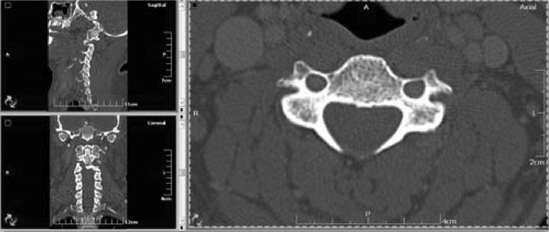
Cervical computed tomography scans showing the sagittal, coronal, and axial views of the lateral masses of the cervical vertebrae.
There were three fixed parameters for screw insertion in this study:
The point of screw insertion was the midpoint of the lateral mass. It was the crossing point between the sagittal and axial planes of the posterior cortex of the lateral mass (Fig. 2).
The direction of the screw in the craniocaudal plane was 30 degrees cranially to avoid facet joint penetration (Fig. 3).
The exit point of the screw was located on the ventral cortex of the lateral mass just lateral to the root of the transverse process in the midaxial cut of each lateral mass to make a sound bicortical fixation without injuring the vertebral artery or the nerve root (Fig. 4).
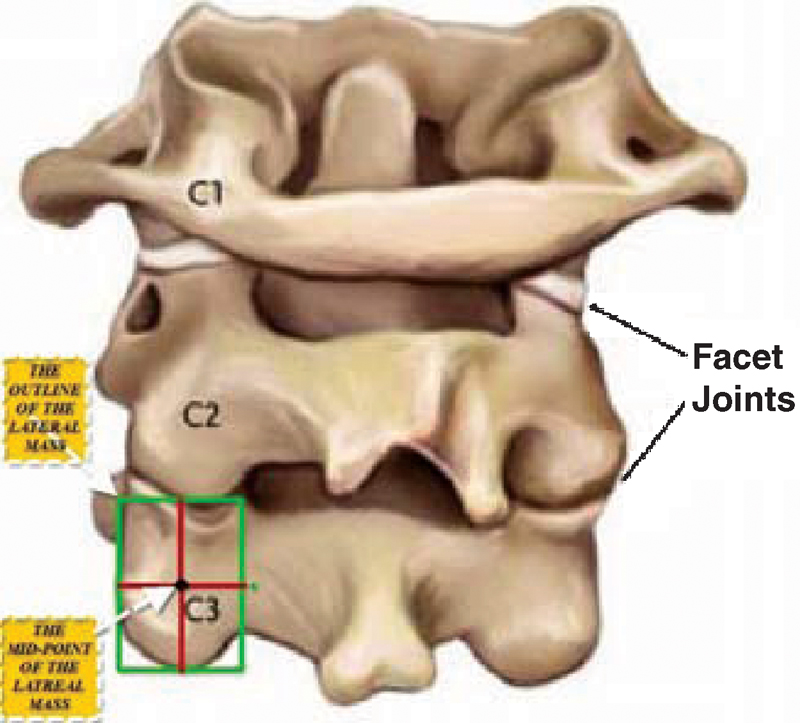
Posterior view of the first three cervical vertebrae with illustration of the left lateral mass of C3 showing its midpoint.
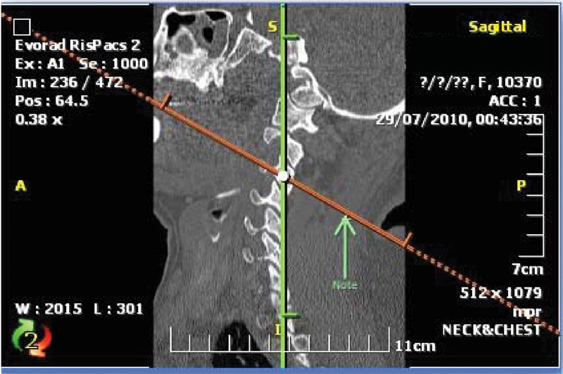
The midsagittal cut of the lateral masses of the cervical computed tomography scan showing the selected plane for screw trajectory, which is tilted 30 degrees cranially in the craniocaudal plane.
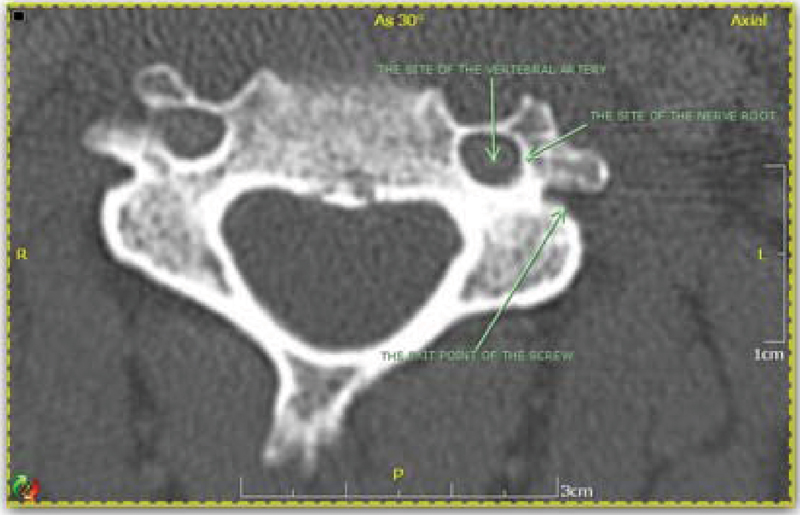
The selected midaxial cut of the computed tomography scan in this study showing the exit point of the screw and its relation with the vertebral artery and nerve root.
The selected screw trajectory in this study was the line drawn between the inlet and exit points, which was always lateral to the sagittal plane.
For measuring the safe divergent angle of bicortical screw insertion without nerve root or vertebral artery violation, the angle between the lateral plane of the screw trajectory (the line drawn between the inlet and exit points) and the sagittal plane was taken.
For measuring the depth of the lateral mass or the length of the screw that can be used in this study, the distance between the inlet and exit points was measured.
For measuring the transverse diameter (the width) of the lateral mass, the starting point is the midpoint of the lateral border of the lateral mass to the midpoint of the medial one.
All measurements were taken for each vertebra starting from C3 to C7.
The 10 cervical cadaveric specimens were subjected to the following: Each specimen was put in prone position. Midline skin incision was done followed by full dissection of posterior soft tissues with exposure of the subaxial cervical vertebrae from C3 to C7. The whole lateral masses and the root of the transverse processes of each vertebra were exposed. The entry point of the screw was located by making the crossing point between the sagittal and axial planes of the posterior cortex of the lateral mass, depending on the visual measures of the surgeon. The direction of the screw in the craniocaudal plane was directed 30 degrees cranially. The exit point of the screw was then located on the ventral aspect of the lateral mass just lateral to the posterior ridge of the transverse process. The metal screw was bicortically inserted taking the previous fixed points, and the relation between the screw and the vertebral artery and nerve root was demonstrated (Fig. 5).
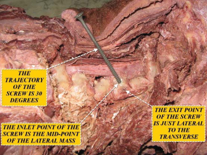
Lateral view of the cervical specimen showing the screw being inserted in the midpoint of the lateral mass, oriented 30 degrees upward, and its exit point just lateral to the transverse process.
In the current study, F test (analysis of variance) was used and was considered statistically significant at p ≤ 0.05.
Results
As regards the collected measurements of the lateral mass of all subaxial cervical vertebrae, the study revealed the following items:
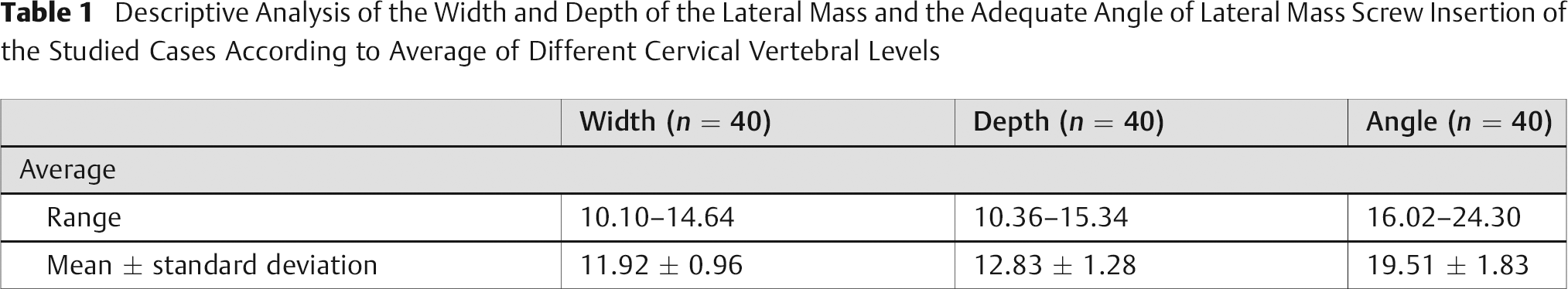
The minimal measured width of the lateral mass was 10.10 mm. The maximal measured width was 14.46 mm. The average was 11.92 ± 0.96 mm (Table 1).
The minimal measured depth of the lateral mass was 10.36 mm. The maximal measured depth was 15.34 mm. The average was 12.83 ± 1.28 mm (Table 1).
The minimal measured divergent angle of bicortical screw insertion without injury to the vertebral artery or the nerve root was 16.02 degrees. The maximal measured angle was 24.30 degrees. The average was 19.51 ± 1.83 degrees (Table 1).
Descriptive Analysis of the Width and Depth of the Lateral Mass and the Adequate Angle of Lateral Mass Screw Insertion of the Studied Cases According to Average of Different Cervical Vertebral Levels
According to this study, as regards all levels of subaxial cervical vertebrae, it was found that:
The minimal width of the lateral mass was at C7 (10.79 ± 0.91 mm), and the maximal width was at C5 (12.59 ± 1.17 mm), with the remaining levels between these values (Table 2). There was significant difference between the widths of the lateral masses of the cervical vertebrae from C3 to C7.
The minimal depth of the lateral mass was also at C7 (9.54 ± 0.99 mm), and the maximal depth was at C6 (13.85 ± 2.70 mm), with the remaining levels between these values (Table 2). There was no significant difference between the depth of the lateral mass from C3 to C6 (ranging from 13.51 ± 1.10 mm to 13.85 ± 2.70 mm), but there was a significant difference at C7 (9.54 ± 0.99 mm).
The minimal divergent angle of safe bicortical screw insertion was at C4 (18.96 ± 2.51 degrees), and the maximal angle was at C6 (20.19 ± 2.54 degrees), with the remaining levels between these values (Table 2). There was significant difference in angles between the lateral masses of C3 and C4 with C6.
Comparison between Different Levels of Subaxial Cervical Vertebrae, as Regards Width and Depth of Their Lateral Masses, and Different Divergent Angles of Bicortical Screw Insertion
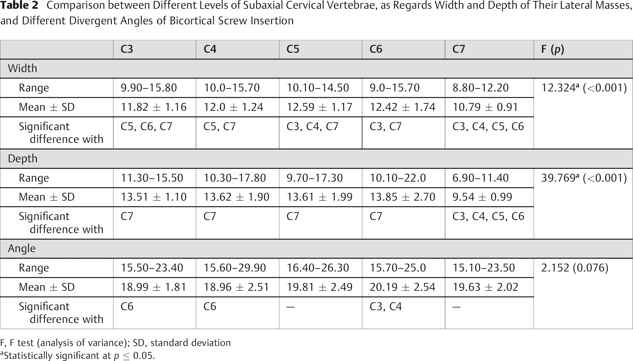
F, F test (analysis of variance); SD, standard deviation
Statistically significant at p ≤ 0.05.
Discussion
There are many techniques of posterior subaxial cervical stabilization such as posterior cervical wires, clamps, and screws. Posterior cervical screws are now the most commonly used among other techniques. Posterior cervical screws are inserted either in the lateral mass, pedicle, lamina, or facet joint. Lateral mass screw fixation has become the method of choice in stabilizing subaxial cervical spine whenever the posterior elements (lamina, spinous process, or pedicle) are absent or compromised. 9 , 10
The main advantages of the lateral mass screw insertion over other posterior cervical screws are that it does not depend on the integrity of the laminae, pedicle, or spinous processes to achieve fixation as in case of cervical wiring, laminar screws, or pedicular screws. It provides superior rotational stability at the facet joints, as it does not penetrate them as in case of transfacet screws. It is safer than transpedicular screws, which carry a high risk of injuring the spinal cord. It can be applied easily without the need of continuous intraoperative imaging. The main limitations of lateral mass fixation are relative risk of injury to the adjacent nerve roots, vertebral arteries, or facet joint; weak grip or purchase of the screw because of less cortical bone in the lateral mass; and small area for bone fusion left after plate insertion. 10 , 11
Many trials in the literature, as well as this study, acquired accurate knowledge about the anatomy of the cervical lateral mass as well as its relationship with cervical nerve root and vertebral artery, which is essential for safe placement of the screws into subaxial cervical spine without fear of injuring these important structures. Roy-Camille and colleagues 12 initially introduced the concept of using a lateral mass screw and plate system to stabilize the cervical spine, then many modifications were made by other investigators 13 , 14 to get the best points of entrance and trajectories for screw insertion. Of these methods, the most commonly used are Roy-Camille and Magerl techniques. Roy-Camille et al 12 advocated that the entrance point for the screw should be located exactly at the midpoint of the lateral mass. The entrance point is then drilled with a 2-mm bit, perpendicular to the vertebral plane and 10 degrees lateral to the sagittal plane. The drill hole is further tapped with a 3.5-mm tap, and a contoured Roy-Camille cervical plate of appropriate length is secured with cortical screws of 3.5-mm diameter. The main anatomic risk when using the Roy-Camille technique is violation of the adjacent facet joints, especially at the lower part of the cervical spine at C5 to C6. Screws violating the articular surfaces should be avoided. Mechanical conflict with the facet joints may produce neck pain, adjacent segment degeneration, and screw pullout. Screws with the Roy-Camille technique are unlikely to cause nerve root injury because their point of exit is midway between the nerve roots. Louis developed another technique in which the starting point for screw insertion is situated slightly above the insertion point of Roy-Camille. The screw hole is drilled with a 2.8-mm bit, and the drill bit is directed strictly parallel to both sagittal and axial planes of the vertebra. The screw should not penetrate the ventral cortex; otherwise it will directly injure the nerve roots. 12
Magerl recommended that the screw entrance point be slightly medial and cranial to the posterior center of the lateral mass and the orientation of the screw should be 20 to 30 degrees lateral and parallel to the adjacent facet. 7
Anderson et al 13 modified Magerl's technique. They recommended that the starting point for screw insertion be 1 mm medial to the center of the four boundaries of the lateral mass and the screw direction be 30 to 40 degrees cephalad (parallel to the facet joint) and 10 degrees lateral to achieve more sound bicortical bony purchase.
An and Coppes 14 recommended that the ideal screw direction should be ~30 degrees lateral and 15 degrees cephalad starting 1 mm medial to the center of the lateral mass for C3 to C6. For C7, special care should be taken during screw placement because the anteroposterior diameter of the lateral mass is thin.
Among the previously mentioned techniques, Roy-Camille's and Magerl's techniques are perhaps the leading techniques of posterior plating of the cervical spine. The ideal exit point with bicortical purchase for the screw in the Magerl technique is located at the anterolateral corner of the superior articular process, and for the Roy Camille technique, the screw it is just lateral to the origin of the posterior ridge of the transverse process. Due to the close anatomic relationship of the screw exit point to the courses of the spinal nerve, the Magerl technique may have a higher incidence of nerve root injury than the Roy-Camille technique, although the former provides more rigid fixation than the latter. If the Magerl technique is to be used, the screw should be directed as lateral and as superior as possible, passing through the upper portion of the superior articular process to avoid injury to the spinal nerve. The exit point for the screw in the Roy-Camille technique seems safe because it lies inferior to the nerve root and is separated from it by the posterior ridge of the transverse process. 12 , 13 , 14 Depending on any of these techniques, one can make a safe lateral mass screw insertion without risk of neurovascular injury.
In the current study, the use of cadaveric specimens was important for demonstration of the anatomic relations between the lateral mass screws and surrounding vital structures such as vertebral artery, nerve root, or facet joint. But it was difficult to depend on them for quantitative measures of the lateral mass. There is some difference between the current study and other studies regarding the maximal and minimal values of the width of the lateral mass for different cervical vertebrae. This can be referred to the differences between the Egyptian populations and others. 15 , 16 , 17 , 18 , 19 , 20
The maximal width in the current study was at C5 but was at C7 in Ebraheim and coworkers’ studies, and the minimal width of the lateral mass was at C7 in the current study but was at C4 or C6 in the Ebraheim studies. 10 , 11 It is noted that the average depth of the lateral mass in all studies depending on Magerl technique for screw insertion is almost always longer than that of all other studies depending on Roy-Camille technique, as the former studies make cranial and lateral angles, giving a chance for the use of longer screws with more sound fixation. 10 , 11 , 12 , 13 , 14 The minimal width of the lateral mass was at C7 (10.79 ± 0.91 mm), and the maximal width was at C5 (12.59 ± 1.17 mm), with the remaining levels between these values. There was significant difference between the widths of the lateral masses of the cervical vertebrae from C3 to C7.
The minimal depth of the lateral mass was also at C7 (9.54 ± 0.99 mm), and the maximal depth was at C6 (13.85 ± 2.70 mm), with the remaining levels between these values.
There was no significant difference between the depth of the lateral mass from C3 to C6 (ranging from 13.51 ± 1.10 mm to 13.85 ± 2.70 mm), but there was a significant difference at C7 (9.54 ± 0.99 mm). There was no significant difference between the current study and other studies regarding the depth of the lateral mass from C3 to C6. The lateral mass of C7 showed the least depth in the current study as well as in other studies, making the lateral mass screw in this level too short to apply sound fixation, so most of the studies in the literature recommended not using lateral mass screw for this particular level. 21 , 22 , 23
The minimal divergent angle of safe bicortical screw insertion was at C4 (18.96 ± 2.51 degrees), and the maximal angle was at C6 (20.19 ± 2.54 degrees), with the remaining levels between these values. As regards the angle, there was significant difference between lateral masses of C3 and C4 with C6.
There was no significant difference between the current study and other studies, using the same point of entry of the screw, regarding the following two points: 2 , 22 , 23
The adequate divergent angle for bicortical screw insertion was almost always less than that of other studies using Magerl's point of entry.
The divergent angle of the screw increased as we went downward in the subaxial cervical vertebrae, with the maximal value at C7.
Conclusion
From this study, we concluded some important points regarding lateral mass fixation in the subaxial cervical spine:
The best point of entry was the midpoint of the lateral mass, which is the point of entry in Roy-Camille's technique.
The first angle made for the screw trajectory was the (30-degree) cranial angle in the craniocaudal plane, to avoid facet joint violation, which is the trajectory used in Magerl's technique.
The second angle made for the screw trajectory was the lateral angle, to make a sufficient screw length for bicortical fixation without injuring the vertebral artery or the nerve root. This angle was based on this study on two fixed points: screw inlet in the dorsal cortex of the lateral mass mentioned above, and screw exit from the ventral cortex of the lateral mass, which is just lateral to the posterior ridge of the transverse process. The line drawn between these two points represented the screw and the lateral angle of this line in the axial plane represented the divergent angle of the screw. The average angle was about 19.51 ± 1.83 degrees for all subaxial cervical vertebrae and increased slightly when progressing downward from C3 to C7.
The average screw length that can be used for bicortical fixation without injuring the vertebral artery or nerve root was about 13.51 ± 1.10 mm from C3 to C6, but at C7 was only about 9.54 ± 0.99 mm.
The average screw thickness that can be used ranged from 3.5 to 4 mm at any subaxial cervical vertebra.
Disclosures
Elrahmany Mohamed, None
Zidan Ihab, None
Anwar Moaz, None
Nabawi Ayman, None
Abo-elw Haitham, None