
Abstract
The cerebral vascular system services the constant demand for energy during neuronal activity in the brain. Attempts to delineate the logic of neurovascular coupling have been greatly aided by the advent of two-photon laser scanning microscopy to image both blood flow and the activity of individual cells below the surface of the brain. Here we provide a technical guide to imaging cerebral blood flow in rodents. We describe in detail the surgical procedures required to generate cranial windows for optical access to the cortex of both rats and mice and the use of two-photon microscopy to accurately measure blood flow in individual cortical vessels concurrent with local cellular activity. We further provide examples on how these techniques can be applied to the study of local blood flow regulation and vascular pathologies such as small-scale stroke.
Introduction
The brain uses more energy than any other organ of the body and relies almost exclusively on moment-to-moment delivery of glucose and oxygen (O2) through the blood. Roy and Sherington (1890), on observing that an increase in neuronal activity caused a local rush of blood into the brain, proposed that neural activity and blood flow were linked. They further postulated that the flow increase existed as a mechanism to support the metabolic demand of active neurons. Our understanding of this phenomenon, commonly termed functional hyperemia or neurovascular coupling, remains an active area of research (Attwell et al, 2010). However, recent studies have highlighted important conditions under which neural activity and blood flow become decoupled (Devor et al, 2008; Jukovskaya et al, 2011; Sirotin and Das, 2008), and thus raise basic questions about neurovascular coupling (Kleinfeld et al, 2011). One set of questions concerns the patterns of neuronal signals that lead to vasoactivity. In particular, what classes of inhibitory vs. excitatory cells have a dominant role and how are their synaptic events converted into dilatory vs. constrictive responses in blood vessels? A second set concerns the role of astrocytes that ensheath the vasculature. In particular, are they intermediary cells that deliver signals from neuron to vasculature (Zonta et al, 2003) or do neuronal signals have a direct effect on blood vessels (Cauli et al, 2004)? A final question set concerns how mechanisms of neurovascular coupling change in response to diseases of the nervous system (Girouard and Iadecola, 2006). In particular, how do the circuits that regulate blood flow break down during stroke and other vascular pathologies. Further, are there mechanisms that can replenish their function after injury?
Techniques to measure blood flow and vascular tone are essential if we are to delimit neurovascular coupling in health and disease. What are the spatial scales that govern these measurements? Although the mouse brain is some 10 mm in extent (Figure 1A), blood flow data is typically analyzed within a cortical column, a region of nominally uniform neuronal activation that extends the full depth of the gray matter (Figure 1B). This corresponds to a cylinder of tissue roughly a few hundred micrometers in diameter and 1 mm in depth in mouse. Single penetrating arterioles, which have the key role of transporting blood from the cortical surface to the subsurface microvasculature, control flow to a similar volume of tissue (Figure 1B) (Bar, 1980). Thus, perfusion changes in a single penetrating vessel can directly impact flow to localized beds of underlying microvessels (Nishimura et al, 2007).
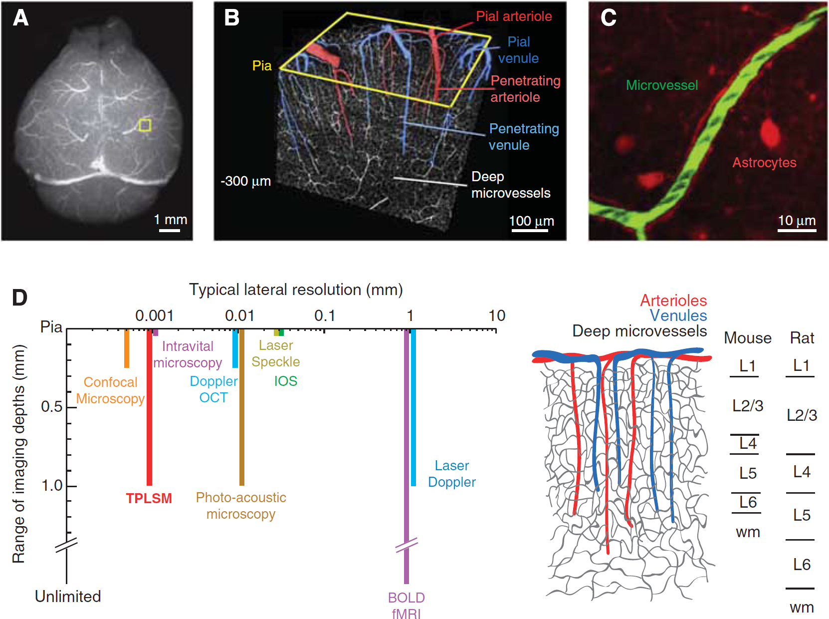
Imaging the microarchitecture of the rodent cerebral vasculature. (
If we consider the flow through a single penetrating arteriole as a single unit of cortical perfusion (Woolsey et al, 1996), how are the spatially and temporally rich patterns of cortical blood flow generated? On the spatial scale of millimeters, flow through tens to hundreds of penetrating arterioles is orchestrated by global control mechanisms, which include the activity of subcortical and brainstem nuclei that project broadly onto the cells and/or vasculature of cortex (Drew et al, 2008; Golanov et al, 2000; Hamel, 2006), cortical gamma rhythms (Niessing et al, 2005; Nir et al, 2008), and intrinsic oscillations in the calcium ion concentration ([Ca2+]int) in vascular smooth muscle (Filosa et al, 2004).
Blood flow regulation on the spatial scale of 1 to 100
Choice of Tools
There is no one tool that can measure from the scale of microvessels to the entire cortical mantle (Figure 1D). The goal of this review is to show that rigorous methods do exist to study blood flow at the micrometer to millimeter spatial scales of vascular function and regulation, i.e., single penetrating vessels and their subsurface branches.
Setting aside the need to image below the pial surface, intravital microscopy, in which the pial surface is imaged at high frame rates, can be used to observe single pial vessels (Ngai et al, 1988). This technique is capable of extracting changes in vessel diameter (Ko et al, 1990; Morii et al, 1986). Concomitant changes in red blood cell (RBC) speed can be collected by intravenous injection of RBCs that have been exogenously labeled with a fluorescent dye (Rovainen et al, 1993; Woolsey et al, 1996). Plasma velocity can be measured by tracking small fluorescent beads that are intravenously injected (Rovainen et al, 1993). However, imaging is restricted to vessels on or close to the pial surface. Thus, diameter changes in subsurface penetrating vessels and microvessels, which are critical for neurovascular coupling, cannot be examined.
Full-field imaging techniques other than intravital microscopy, including intrinsic optical imaging (Frostig et al, 1990; Grinvald et al, 1986) and laser speckle imaging (Dunn et al, 2001), yield information about changes in blood oxygenation and/or blood flow, but are inappropriate for measuring flow below the cortical surface at high resolution. Laser Doppler imaging measures flow deep to the brain surface but also suffers from low spatial resolution (Ances et al, 1999). Blood-oxygenation level-dependent functional magnetic resonance imaging (BOLD fMRI) has no restriction to the depth of imaging, but temporal and spatial resolution are also low (Ogawa et al, 1992). Emerging techniques such as optical coherence tomography (Srinivasan et al, 2009, 2011), photoacoustic microscopy (Hu and Wang, 2010), and functional ultrasound imaging (Mace et al, 2011) are gaining the capacity to resolve flow in large numbers of individual vessels in cortex and may be able to address issues regarding global flow regulation. Critically, none of these methods currently combine imaging of blood flow and cellular activity at high resolution, and are thus less appropriate for studies seeking to link cellular activity with blood flow.
The use of confocal laser-scanning microscopy improves the ability to measure flow in single vessels concurrent with indicators of cellular activity below the pial surface. Here, the vascular serum is labeled with a fluorescent dye to visualize the whole vessel lumen. The dye is conjugated to a high-molecular-weight dextran to prevent its leakage from the vasculature. Non-fluorescent RBCs are then tracked on this fluorescent background (Dirnagl et al, 1989). The optical sectioning capabilities of this method allow imaging of subsurface vessels down to ∼100
We suggest that TPLSM is the method of choice for the imaging of blood flow (Driscoll et al, 2011a; Helmchen and Kleinfeld, 2008; Kleinfeld et al, 1998, 2008; Kleinfeld, 2002; Shih et al, 2009; Tiret et al, 2009). Past studies have made use of TPLSM to examine vascular dynamics in somatosensory cortex (Blinder et al, 2010; Brown et al, 2007; Devor et al, 2007, 2008; Drew et al, 2011; Fernández-Klett et al, 2010; Hutchinson et al, 2006; Kleinfeld et al, 1998; McCaslin et al, 2010; Nishimura et al, 2007, 2010; Schaffer et al, 2006; Shih et al, 2009; Sigler et al, 2009; Stefanovic et al, 2007; Tian et al, 2010; Wang et al, 2006; Winship et al, 2007; Zhang et al, 2005; Zhang and Murphy, 2007) and the olfactory bulb (Chaigneau et al, 2003, 2007; Jukovskaya et al, 2011; Lecoq et al, 2009; Petzold et al, 2008). Recent advancements show that TPLSM can allow single microvessels to be studied throughout the full depth of cortex (Kobat et al, 2009), which is important as vascular regulation appears to initiate in middle and deeper layers of cortex (Tian et al, 2010). A further advantage is the ability to use of fluorescent-based functional reporters or endogenous signals to record cellular activity, such as changes in [Ca2+]int (Chaigneau et al, 2007; Petzold et al, 2008; Wang et al, 2006), and the ratio of [NADP]int to [NAD+]int (Kasischke et al, 2011; Murphy et al, 2008b) concurrent with blood flow and vessel diameter changes. Last, TPLSM may be used to image subsurface vasodynamics through a chronic window in awake mice (Drew et al, 2010b, 2011).
How Can Two-Photon Laser-Scanning Microscopy Help Delimit the Logic of Neurovascular Coupling?
Neurovascular coupling is thought to occur locally, through a complex interplay of signaling cascades among neuronal processes and astroglial endfeet that surround the vascular wall (Attwell et al, 2010; Iadecola and Nedergaard, 2007). The hemodynamic response is dominated by arteriole dilation at the center of the response, where neural activity is most pronounced (Derdikman et al, 2003; Devor et al, 2008), whereas the surrounding regions are dominated by delayed arteriole constrictions that lead to an overall decrease in flow (Devor et al, 2008). What signals generate this spatiotemporal pattern of blood flow? Although multiple vasoactive pathways have been identified, their roles in generating a hemodynamic response remain unclear (Attwell et al, 2010; Kleinfeld et al, 2011). Two-photon imaging, which has been used with great rigor in slice experiments (Gordon et al, 2008; Mulligan and MacVicar, 2004), can meet the necessary challenges to dissect these pathways
An additional line of research that stands to gain from TPLSM is the basis of dysfunction or blockade of a single microvessel and its relation to cortical pathology. A significant proportion of human stroke cases involve obstruction of small cerebral vessels, possibly leading to microinfarctions (Das et al, 2008). The accumulation of multiple small strokes during atherosclerosis or amyloid angiopathy may lead to long-lasting deficits in function and cognition, as seen with different forms of dementia (Gold et al, 2007; Suter et al, 2002). Rodent models to study the consequences of small vessel disease (Hainsworth and Markus, 2008) require measurement and manipulation of flow in single vessels, both at the pial surface (Blinder et al, 2010; Nguyen et al, 2011; Nishimura et al, 2007, 2010; Schaffer et al, 2006) and in subsurface microvessels (Nishimura et al, 2006). Of particular importance is the use of chronic preparations where the consequences of vascular obstruction can be studied longitudinally (Drew et al, 2010b).
Focus of this Review
Here, we provide details on how to perform single- and multivessel TPLSM imaging of blood flow dynamics, concurrent with cellular activity, in the somatosensory cortex of anesthetized and awake rodents. First, we compare advantages and disadvantages of using rat and mouse species for blood flow imaging studies. Second, we describe the surgical tools and procedures used to generate acute and chronic cranial windows; video resources for chronic imaging windows are available (Marker et al, 2010; Shih et al, 2012). Third, we discuss how blood flow imaging data are collected using TPLSM and the calculation of relevant flow parameters from single cerebral vessels. Finally, we provide case studies on how auxiliary lasers and cell-labeling techniques can be used to address critical questions concerning neurovascular function in health and disease. The equipment and algorithms used in these studies have been summarized elsewhere, including basic hardware (Driscoll et al, 2011b; Tsai and Kleinfeld, 2009) and software (Nguyen et al, 2006, 2009) for TPLSM, and algorithms for data analysis (Drew et al, 2010a; Driscoll et al, 2011a; Kleinfeld and Mitra, 2011; Valmianski et al, 2010). Additional work has addressed the use of TPLSM to image histological tissue with labeled vasculature (Kleinfeld et al, 2011; Ragan et al, 2007; Tsai et al, 2003, 2009, 2011).
Methodological overview
Mouse vs. Rat and Chronic vs. Acute Preparations
Both rats and mice have their place in cerebral blood flow imaging studies. It is important to choose the model species based on the goal of the experiment. Rats, for example, are larger animals and thus preferred for complex surgical procedures. Cranial windows can be made large to allow access to multiple regions of cortex and physiological parameters can be more easily controlled. However, a major disadvantage is that imaging quality of rat cranial windows tend to degrade within days. In contrast, mice are excellent for repeated imaging studies as transcranial windows with a thinned skull are generally stable for months. The use of mice allows researchers to exploit a wide range of vascular-related transgenics that now exist. However, physiological parameters are more difficult to control with anesthetized mice.
Physiological Variables
An important factor for blood flow imaging in anesthetized rodents is the maintenance of levels of blood gas, blood pressure, and body temperature within an accepted physiological range. Deviations from the normal physiological state leads to abnormal vascular dynamics. Simply maintaining stable anesthesia is often insufficient as prolonged periods of anesthesia lead to an increase in the partial pressure of carbon dioxide (pCO2) in the blood and a decrease in blood pressure, which in turn lead to gradual vasodilation (Lassen and Christenson, 1976). Rats, because of their larger size, allow for the best control of physiological variables as arterial and venule catheters are easier to place and more blood can be drawn for intermittent monitoring of blood gas (Waynforth and Flecknell, 1992). A femoral artery catheter also serves as a means to continuously monitor blood pressure via an attached pressure transducer. The alternative is to use a pressure cuff transducer, which is noninvasive but permits only intermittent measurements.
Assessment of physiological variables in mice requires more surgical skill than for rats. An important consideration is that the total amount of blood for a 30 g mouse is only ∼2.4 mL (Harkness and Wagner, 1989), and each withdrawal of blood for measurement in a conventional blood-gas monitor will reduce blood volume by ∼4% (McGuill and Rowan, 1989). Repeated sampling of blood over a short period of time would undoubtedly alter vasodynamics. Thus, blood-gas machines that read smaller blood samples, e.g., <100
Two-photon imaging studies of rodents are rapidly moving toward the use of behaving animals (Dombeck et al, 2007; Greenberg et al, 2008; Sawinski et al, 2009), including studies of blood flow (Drew et al, 2011), and the determination of physiological variables will also prove to be critical. Fluctuations in blood pressure may occur during heightened stress or physical activity, and will influence cerebral blood flow. To measure such changes chronically in awake imaging studies, indwelling and remotely transmitted monitors for blood pressure could be used for some experiments (Butz and Davisson, 2001). Although technically very challenging in mouse, chronically implanted arterial and venule catheters enable researchers to draw blood and deliver drugs without added stress to the animal. Finally, implanted wire electrodes to collect ongoing electrocorticograms and electrocardiograms allow noninvasive monitoring of brain state and heart rate, respectively (Pinnacle Technology Inc., Lawrence, KS, USA).
The main advantage of an acute anesthetized preparation is that it allows rigorous physiology monitoring. Blood gas and pressure can be ‘tuned’ to a normal physiological state by adjusting anesthesia and the use of pharmacological agents. In contrast, chronic imaging preparations will almost always be less physiologically controlled as many methods for physiological monitoring are too invasive for survival studies. Yet chronic imaging of awake animals obviates concerns regarding homeostasis, particularly suppressed autoregulation of the vascular supply caused by anesthetics (Hoffman et al, 1991).
Cranial Windows
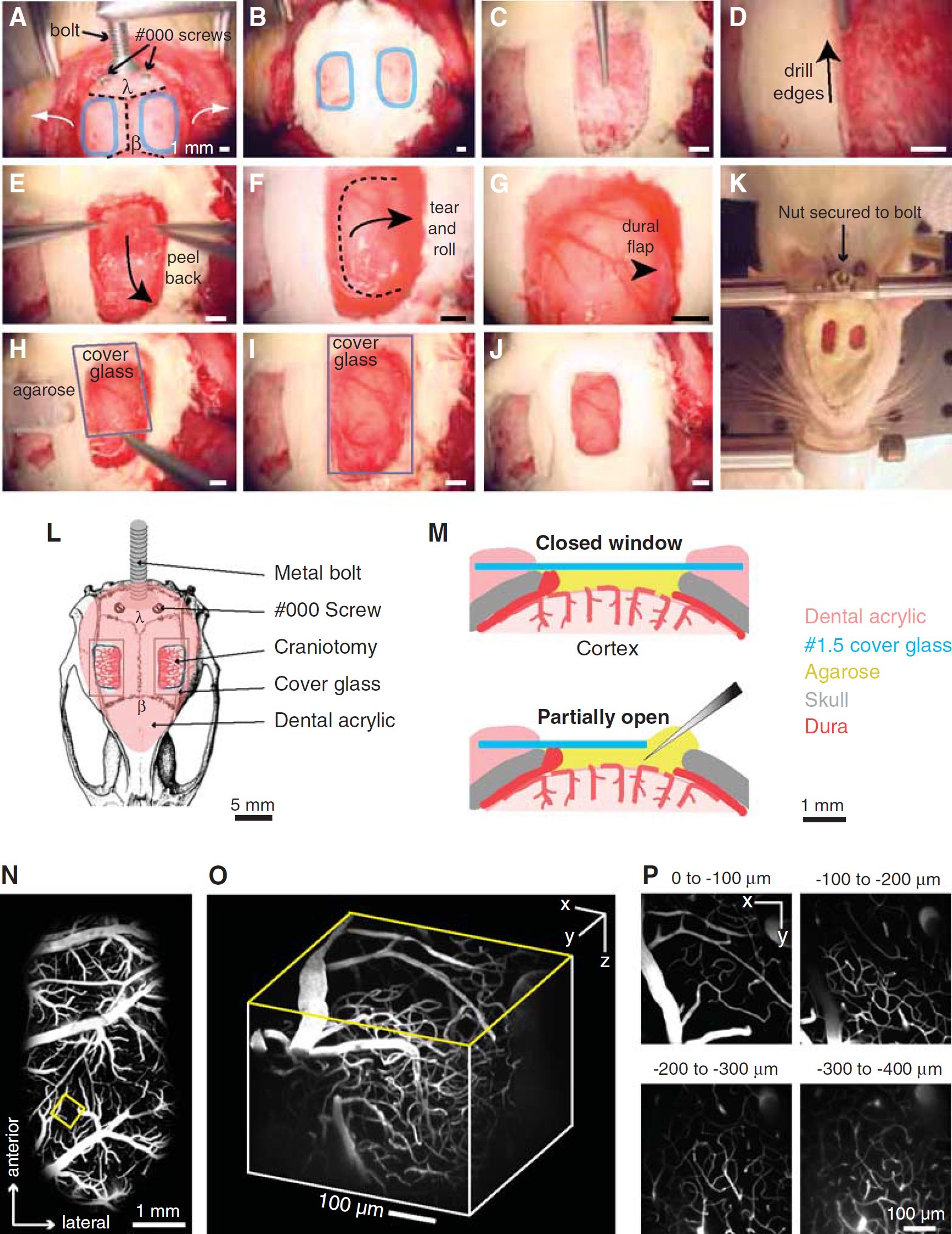
The generation of a cranial window for optical access in rats and mice differ on a number of levels. In rats, the overlying bone must be completely removed. Further, the dura mater must be carefully resected to the edge of the imaging window for TPLSM (Kleinfeld and Delaney, 1996; Levasseur et al, 1975; Morii et al, 1986). The window must then be resealed to restore intracranial pressure and to minimize motion artifacts caused by heart beat and breathing (Figure 2). The clarity through such a cranial window is initially optimal as the materials overlying the pial surface cause minimal scattering. Very large windows, i.e., 4 × 6 mm2, can be generated to facilitate easy positioning of electrodes and cannulae. However, a disadvantage of cranial windows in rats is the disruption of the intracranial pressure and exposure of the cortex to air. As a result, an inflammatory reaction is unavoidable even in the most carefully generated preparations. In our hands, rat cranial windows can be imaged for approximately 4 days, after which dural regrowth begins to degrade the imaging quality. Chronically implanted windows for repeated imaging in rats are rarely reported and the use of pharmacological agents to suppress inflammation may also affect the phenomenon under study, such as the magnitude of injury in experimental stroke models (Tuor et al, 1993). Window clarity may be maintained longer by overlaying the brain with inert substances such as Kwiksil silicone, as has been used in mice (Dombeck et al, 2009).
Procedure for rat dura-removed craniotomy. (
Cranial windows in mice are surgically less demanding, as the dura is thin and does not need to be removed for optical access. Detailed methods have been described for chronic bone-removed cranial windows (Holtmaat et al, 2009; Mostany and Portera-Cailliau, 2008) and semi-chronic thinned-skull windows (Yang et al, 2010). Here, we focus on a method where the skull is thinned, polished, and reinforced with a thin layer of glue and cover glass (Figure 3;Drew et al, 2010b). This method allows the generation of a stable and relatively large window, i.e., 2 × 2 mm2, which greatly minimizes disruption of the intracranial milieu, reduces inflammation, and prevents bone regrowth. Although the imaging depth and clarity are reduced compared with complete bone removal, polished and reinforced windows in mice provide excellent clarity for TPLSM imaging months after the initial surgery.
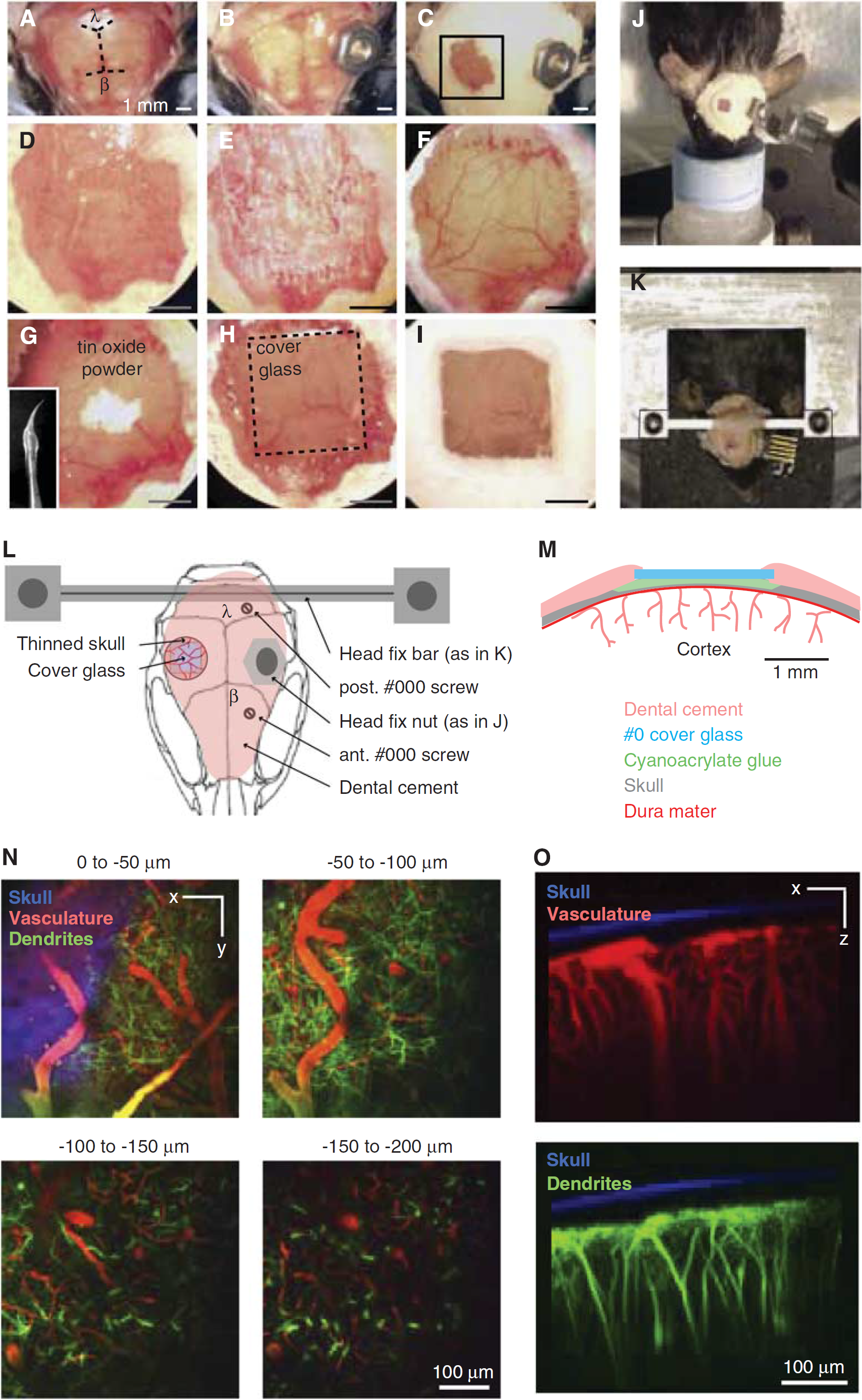
Procedure for mouse polished and reinforced thinned-skull (PoRTS) window. (
Genetics and Behavior
Mice are becoming increasingly important with the advent of transgenic lines with fluorescently labeled components of the neurovasculature (Kleinfeld et al, 2011). Many are engineered to express fluorescent proteins under control of cell-specific promotors, which enable identification of almost any cell type, including glia (Nolte et al, 2001; Zhuo et al, 1997), excitatory neurons (Madisen et al, 2010), inhibitory interneurons (Chattopadhyaya et al, 2004; Ma et al, 2006; Oliva et al, 2000; Tamamaki et al, 2003), pericytes (Zhu et al, 2008), arterial smooth muscle (Xin et al, 2002), endothelial cells (Motoike et al, 2000), and microglia (Jung et al, 2000). Some of these lines also express CRE-recombinase under the same promoters and can, in principle, be combined with animals or viruses carrying FLOXed gene cassettes to achieve cell-specific gene expression (Kuhlman and Huang, 2008; Madisen et al, 2010). This powerful strategy may be used to express sensors of cell activity (Akemann et al, 2010; Mank et al, 2008; Tian et al, 2009), light-based mediators of cell depolarization (Boyden et al, 2005) or hyperpolarization (Chow et al, 2010), chemical-based mediators of cell depolarization (Alexander et al, 2009; Fiacco et al, 2007), or small hairpin RNAs to disrupt specific signaling pathways (Babcock et al, 2005). In addition, a variety of mice with perturbations of potential vascular signaling pathways, such as nitric oxide synthase knockouts (Meng et al, 1996) or inositol-triphosphate 3 receptor knockouts (Li et al, 2005), are used in blood flow-related studies. In future studies, inducible knockouts will be of increasing value, as compensatory gene expression could be at play with chronic loss of gene function. Specific gene manipulations that lead to neurodegeneration (Kuchibhotla et al, 2009), white matter disease and spreading depression (Eikermann-Haerter et al, 2011), or vascular growth abnormalities (Murphy et al, 2008a) are potentially critical tools for studying vascular pathology in slowly progressing diseases, such as dementia and neurodegeneration (Misgeld and Kerschensteiner, 2006).
Transgenic technologies have not translated well to rats, which is unfortunate because the majority of our knowledge of rodent vascular physiology comes from rat studies. Rats also exhibit more complex behaviors and have classically been the model of choice for detailed fine motor control and sensory tasks (Hutson and Masterton, 1986; Knutsen et al, 2006; Krupa et al, 2001; Maaswinkel and Whishaw, 1999; Mehta et al, 2007) and memory-based tasks (D’Hooge and De Deyn, 2001) that may be relevant to vascular pathology. However, recent studies show that mice can be habituated and trained to perform head-fixed behavioral tasks (Komiyama et al, 2010; O’Connor et al, 2010). These techniques will be essential for linking blood flow and neural activity in awake preparations. Given the time investment required for behavioral training, the long-term stability of a mouse cranial window is an important benefit.
Detailed methods
Common surgical materials and procedures to prepare cranial imaging windows in rat and mouse are provided first. We then provide specific protocols for generating: (i) a dura-removed cranial window for studies in rat and (ii) a reinforced thinned-skull window for studies in mouse. All surgical procedures were approved by the Institutional Animal Care and Use Committees at UCSD and Cornell University.
Surgical Materials
The following materials are suggested when performing surgeries and TPLSM imaging of rodents.
Reagents
Appropriate anesthetic (Table 1).
Common anesthetic agents IP, intraperitoneal; IV, intravenous; MAC, mean alveolar concentration; NMDA, 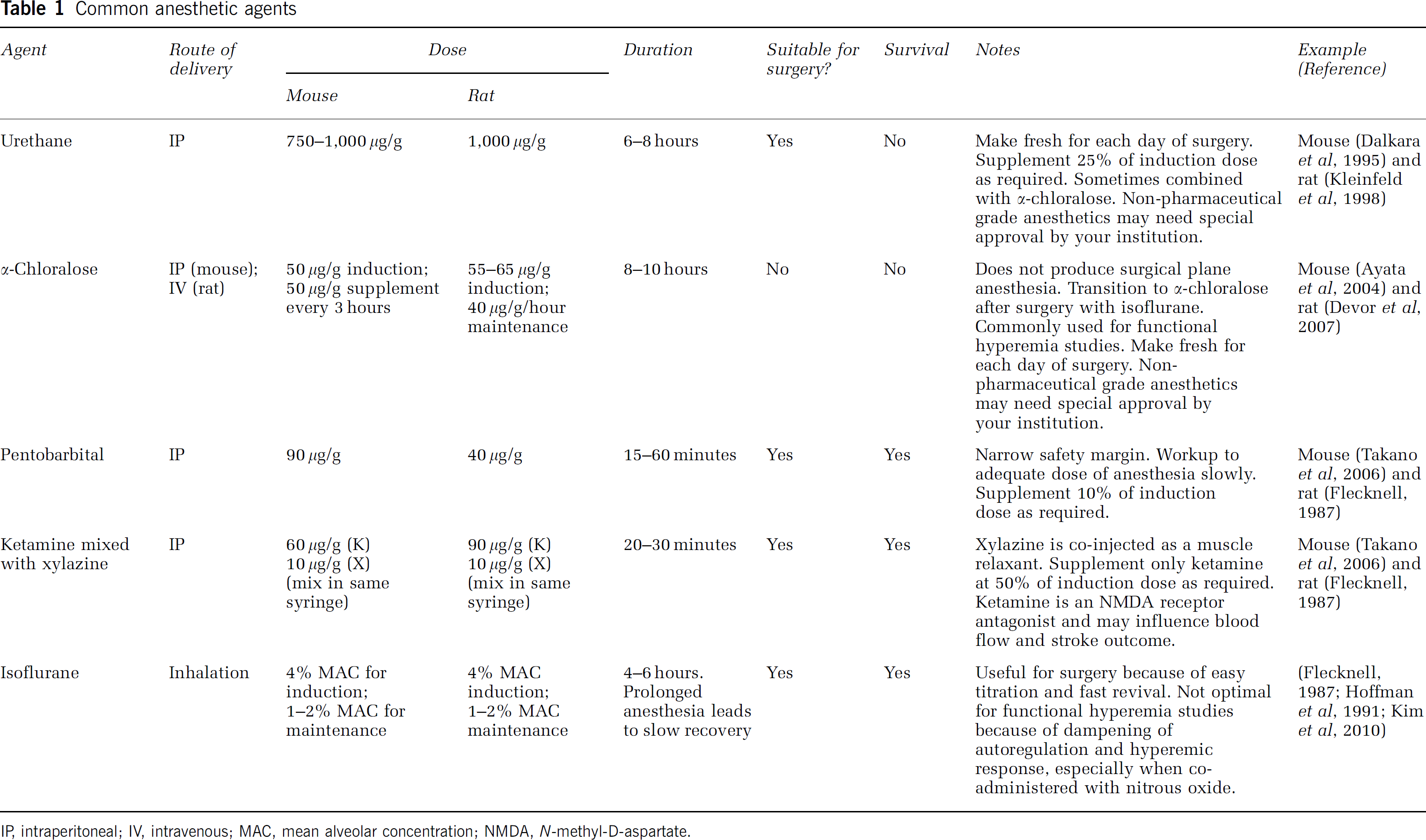
Betadine (6906950; Butler Schein).
Buprenorphine hydrochloride (Buprenex; 031919; Butler Schein, Dublin, OH, USA).
Fluorescent agents for blood labeling
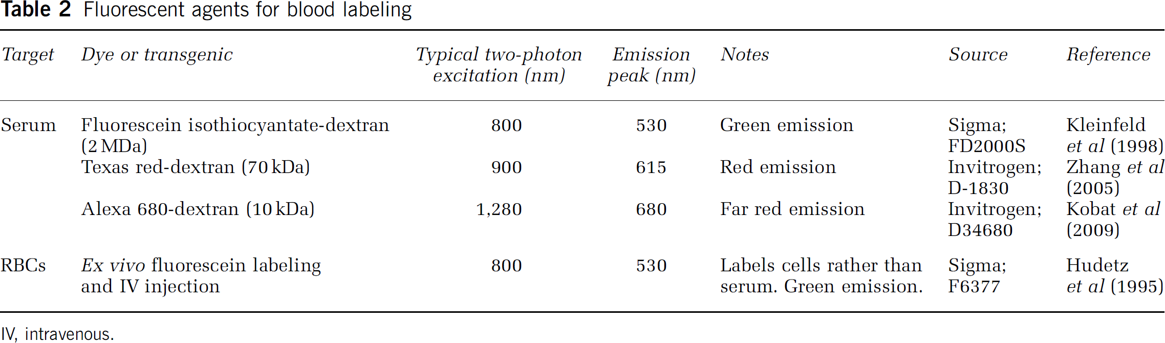
IV, intravenous.
Isopropyl alcohol, dissolved to 70% (v/v) in water (I9030; Sigma-Aldrich, St Louis, MO, USA).
Lactated Ringer's solution (009846; Butler Schein).
Modified artificial cerebral spinal fluid (mACSF), free of carbonate and phosphate (125 mmol/L NaCl, 10 mmol/L glucose, 10 mmol/L HEPES, 3.1 mmol/L CaCl2, 1.3 mmol/L MgCl2, pH 7.4; all chemicals from Sigma; Kleinfeld and Delaney, 1996). This recipe is used when forming a clear layer of agarose under the cover glass, as carbonate and phosphate precipitates are generated when regular ACSF is heated to melt the agarose. For simplicity, we use mACSF in both mouse and rat procedures, but regular ACSF may be used when agarose is not involved.
Saline (009861; Butler Schein).
Tool cleaning solutions (Surgical Milk, 014325 and Maxizyme, 035646; Butler Schein).
Disposables
Bone wax (032005; Butler Schein). Cotton-tipped applicators (23-400-100; Fisher Scientific, Waltham, MA, USA). Cyanoacrylate glue (31428 H04308; ND Industries, Clawson, MI, USA). Dental cement (Grip Cement powder, 675571, and solvent, 675572; Dentsply, York, PA, USA). Drill burrs (For an air drill, 035624 and 035603; Butler Schein, for an electric drill, 19007-05; Fine Science Tools, Foster City, CA, USA). Kimwipes (06-666A; Fisher Scientific). Opthalmic ointment (039886; Butler Schein). Scalpel blades (12-460-448; Fisher Scientific). Screws, self-tapping #000 (FF000CE125; J.I. Morris Company, Southbridge, MA, USA). Surgical gauze (22-362-178; Fisher Scientific). Syringe needle (26 G, 036321; Butler Schein). Syringe plungers (1 cc, 9870250; Butler Schein).
Equipment
Blood gas monitor (RapidLab 248; Bayer, or equivalent). Blood pressure monitor (BP1 and pressure transducer, World Precision Instruments (Sarasota, FL, USA) for intra-arterial; XBP1000, Kent Scientific (Torrington, CT, USA) for rat tail cuff measurements). Dental drill, air powered with foot-pedal control (Midwest Quiet Air; Dentsply). Electric powered drills are also suitable (K.1020; Foredom or EXL-M40; Osada, Los Angeles, CA, USA). Dissecting microscope (OPMI-1 FC or equivalent; Carl Zeiss, Thornwood, NY, USA). Electrical razor (Series 8900; Wahl, Sterling, IL, USA). Forceps, Dumont no. 55 (11255-20; Fine Science Tools). Forceps, serrated (11050-10; Fine Science Tools). Glass scribe to cut cover glass (08-675; Fisher Scientific). Heating pad with feedback regulation (Temperature control system, 40-90-8, rectal thermistor for rat and mouse, 40-90-5D-02, heat pad for rat, 40-90-2-05, heat pad for mouse, 40-90-2-07; FHC Inc., Bowdoin, ME, USA). Hemostats (no. 105-1105; George Tiemann, Hauppauge, NY, USA). Isoflurane vaporizer (IsoTec4; Datex-Ohmeda GE Healthcare, Waukesha, WI, USA). Pulse oximeter (MouseOx; Starr Life Sciences, Oakmont, PA, USA). Screwdriver, miniature (26B09.01; Garret Wade, Cincinnati, OH, USA). Stereotaxic frame, with rat or mouse ear and bite bars (Model 900; David Kopf, Tujunga, CA, USA). Surgical scissors, blunt end (14078-10; Fine Science Tools). Ultrasonic cleaner (15-335-30; Fisher Scientific).
Specific Materials for Rats
Agarose, Type III-A (A9793; Sigma). Cover Glass, no. 1.5 thickness (12-541B; Fisher Scientific). Nut and bolt to secure the head (A35230-ND and H350-ND; Digi-Key, Thief River Falls, MN, USA) or a custom-made head frame (Kleinfeld et al, 2008). Periosteal elevator (RS-8820; Roboz, Gaithersburg, MD, USA). SurgiFoam (6547781; Butler Schein). Sutures, 4-0 silk (SS683; Covidien, Mansfield, MA).
Specific Materials for Mice
Cover glass, no. 0 thickness (6661B40; Thomas Scientific, Swedesboro, NJ, USA). Insulin syringe, 0.3 mL volume with a 29.5-G needle (018384; Butler Schein). Nut and bolt to secure the head (H723-ND and R2-56X1/4-ND; Digikey) or a custom-made head-frame (Drew et al, 2010b). Silicone aquarium sealant (31001; Perfecto Manufacturing, Noblesville, IN, USA). Tin oxide powder (EQT-TINOX; Mama's Minerals, Albuquerque, NM, USA).
Surgical Preparation
Common Procedures
The following procedures are common across all laboratory animals.
Ensure that your local Institutional Animal Care and Use Committee have approved all animal surgery procedures required for your experiment. Induce anesthesia (Table 1). Ensure a surgical plane of anesthesia by checking for a lack of the toe pinch reflex. Shave the scalp with an electrical razor. Secure animal in stereotaxic frame (Cetin et al, 2006). Apply opthalmic ointment to eyes to retain moisture. Inject lactated Ringer's solution intraperitoneally at a volume of 3 mL per kg every 2 hours to maintain body fluids and energy requirements. For sterile surgery, clean the scalp with betadine followed by 70% (v/v) isopropyl alchohol. After surgery, clean surgical tools by sonicating in Maxizyme and Surgical Milk in an ultrasonic cleaner. Dry the tools thoroughly and autoclave before each sterile surgery.
Optional Procedures
Place a femoral vein catheter if drugs, such as the anesthetic Intubate by means of a tracheotomy if the animal is to be artificially ventilated (Short, 1987). Alternatively, intubation can be performed noninvasively using a laryngoscope, which is suitable for survival experiments (Costa et al, 1986; Waynforth and Flecknell, 1992).
Physiological Monitoring
Ensure heart and breathing rates are within a normal range using a pulse oximeter. These values should center around 6 and 1 Hz, respectively, for a rat and 10 and 2 Hz, respectively, for a mouse. Maintain body temperature at 37°C using a feedback regulated rectal probe and heat pad. Monitor arterial blood pressure continuously from a femoral arterial line. Alternatively, the tail cuff method can be used for rats to noninvasively measure blood pressure at intermittent time points. Mean arterial blood pressure should be maintained between 80 and 120 mm Hg. Arterial blood gas and pH can be measured once before and once after the experiment to ensure that values have not drifted over the course of the experiment. Blood pO2 should be between 80 and 100 mm Hg, pCO2 should be between 35 and 45 mm Hg, and pH should be between 7.35 and 7.45.
Acute Imaging Preparation for Rats: Dura-Removed Cranial Window
This preparation is primarily for imaging studies lasting 1 to 4 days and provides ample opportunity for the measurement and control of physiological parameters as well as for electrophysiological recording and drug delivery. It provides excellent optical clarity and exposes a large region of cortex, i.e., typically 3 × 6 mm2. Further, a maximal imaging depth of 500
Make a 4 to 5 cm incision down the midline of the scalp using a scalpel blade. Start the incision from between the eyes and cut to just caudal of the ears. Retract the scalp to the side of the head with four hemostats, two placed on either side caudally and two placed rostrally. Control bleeding with gauze.
Use a periosteal elevator to remove the thin periosteum from the surface of the skull (Figure 2A). Control bleeding from the areas of skin and soft tissue by applying constant pressure to the bleeding tissue with a pair of hemostats and removing excess blood with gauze and cotton applicators. Both the bregma (
Stop any bleeding from vessels emanating from the skull by using light, focused abrasion with 1/2 mm dental drill burr.
Separate the temporal muscle from the temporal ridge, which runs along the lateral aspects of the skull (Figure 2A, white arrows). Apply direct pressure to the muscle where it attaches to the skull using the periosteal elevator. Avoid separating the muscle near the eye to prevent a rip to the infraorbital vein. Rather, separate the muscle as caudally as possible past the squamosal bone, which is roughly lateral to the lambda point. If desired, retract the muscle away from the skull with hemostats on both sides of the skull. Note that one can make bilateral windows to maximize use of each animal, and to potentially study bi-hemispheric changes in blood flow (Figures 2A and 2K).
Demarcate the location of the desired cranial window (Figure 2A, blue circles). As an example, primary somatosensory cortex, which is the part of parietal cortex, nominally lies between −1 and −5 mm relative to the bregma point and between 1 and 7 mm from the midline on the medial-lateral axis for rats (Paxinos and Watson, 1986). However, imaging of blood flow and/or cellular dynamics can be performed in any brain region that lies near the skull. The zygomatic arch may need to be removed when imaging more lateral structures such as auditory cortex.
Attach a metal connector to the skull with dental acrylic for immobilization of the head during imaging (Figures 2A and 2L). The connector could be a custom-fabricated metal frame (Driscoll et al, 2011a; Kleinfeld and Denk, 1999) or simply a nut and bolt system with a horizontal cross bar, as shown (Figure 2K). Clean the contact regions of soft tissue to achieve a reliable connection between acrylic and bone. Apply a thin layer of cyanoacrylate glue to the bone. Introduce small self-tapping screws to the skull to reinforce the linkage of the connector to the skull, just posterior to lambda. Care should be taken when drilling pilot holes, as the transverse sinus lies directly beneath the lambda suture line.
Apply dental cement to the entire assembly. Cover the entire exposed skull surface with dental cement except where the window will be placed (Figures 2B and 2L). Fill the space between the skull and the retracted temporal muscle. Build a slight wall around the window region, which will eventually hold the agarose and keep the overlying cover glass from touching the brain surface. The wooden handle of the cotton-tipped applicator can be snapped to make a fine tip for trailing small amounts of dental cement around the window.
Using a high-speed dental drill with a 1/2 mm burr, thin the skull evenly throughout the entire window (Figure 2C). Flush the surface frequently to reduce heating during drilling, and continue to thin until the underlying pial vasculature becomes visible after application of mACSF. The skull should be less than 1/4th of its original thickness at this point. This requires thinning through the vasculature of the skull, which may bleed, but can be controlled by flushing with mACSF.
Carefully thin the edges of the window with a 1/4 mm burr until a network of fine cracks in the bone begins to show (Figure 2D).
Soak the window with mACSF for 1 minute to allow the bone to soften, and then wick the liquid away with KimWipes.
Use a pair of forceps to gently separate connected segments of the bone flap from the skull, but do not yet remove the bone flap completely. Again, control bleeding from the dura by flushing with mACSF.
Soak the window with mACSF for another minute to soften the bone, and wick the liquid away.
Use forceps to grasp the far corners of the loosened bone flap, and slowly peel it away from the underlying dura mater (Figure 2E). Peel carefully at skull suture lines, as the underlying dura may be attached to the bone.
Flush the dural surface with mACSF and apply small pieces of SurgiFoam presoaked in mACSF to control bleeding. The serpentine-like dural vessels will be clearly visible at this point. All bleeding must be stopped before proceeding to the next step.
Retract the dura to the edges of the window (Figure 2F). This must be done with extreme care, because the dura is thin and close to surface of the cortex. First generate a small incision in the dura using the cutting edge of a 26-G syringe needle. Bend the needle to an obtuse angle with hemostats to ensure the cutting edge punctures the dural membrane but does not damage the underlying cortex.
Using two sharp no. 55 forceps, gently lift the dura away from the cortical surface, starting at the incision site, and tear in small increments (Figure 2F). Whenever possible, tear around large dural vessels to avoid bleeding. Limit any bleeding from dural vessels with small pieces of SurgiFoam soaked in mACSF or moistened KimWipes, twisted to a fine point with the fingers. If bleeding from the dura is excessive, flush with a slow flow of mACSF across the window until bleeding ceases.
Tear along three edges of the window, and roll the dural flap to the side of the window (Figures 2F and 2G). Flush the cortical surface with mACSF. It is crucial to avoid any damage to pial vessels. Hemorrhaging will alter cerebral blood flow, accelerate brain swelling, and severely degrade imaging quality. Removal of the dura and subsequent sealing of the window should be done swiftly, i.e., within 10 minutes, to avoid brain swelling.
Overlay the window with 1.5% (w/v) low-melting point agarose dissolved in mACSF (Figures 2H and 2M;Kleinfeld and Delaney, 1996). Dissolve the agarose in mACSF by heating in a microwave, using short periods of heating to prevent boiling. The agarose should be prepared ahead of time and maintained in a 60°C water bath. Draw the agarose mixture into a 1 mL syringe, and allow to cool slightly before applying 3 to 4 drops to the cortex; the agarose should not feel hot on the back of the hand. Then immediately seal the chamber using a precut cover glass that is larger than the size of the craniotomy. Ensure that the cover glass is not pressing against the cortical surface, as this will impede blood flow and lead to poor imaging quality over time (Figures 2I and 2M).
Apply dental cement to the edges of the cover glass (Figures 2J and 2M, upper panel). Build up the cement slightly to hold water for the dipping lens. Sealing the craniotomy is crucial to protect the cortex and suppress motion from cranial pressure fluctuations because of heartbeat and breathing. However, an edge of the window can remain uncovered to allow insertion of electrodes or micropipettes (Figure 2M, lower panel). In this case, apply ample agarose to the exposed edge as evaporation will eventually cause the agarose to dry. The perfusion of drugs over the cortical surface can also be achieved by adding tubing and an agarose-covered ‘vent’ that allows fluids to directly reach the cortical surface (Nishimura et al, 2010). Be aware that using glass pipettes with diameters >10
Suture the scalp so that it fits snugly around the head mount. Excess skin around the head mount should be cut early in the procedure, as bleeding from the skin takes 10 to 15 minutes to completely stop. Compress the cut edges with hemostats for 10 to 15 seconds to help minimize bleeding. When all bleeding has stopped, protect the exposed edges of the scalp by covering with dental cement. Apply additional dental cement around the metal connector for further reinforcement (Kleinfeld and Denk, 1999).
Stabilize the animal on an optical breadboard for imaging, using the frame as a head support (Figure 2K). The animal should be slightly suspended by the head mount, to prevent motion artifacts from breathing. Here, we use a custom-machined cross bar with a hole for the bolt. The bolt is inserted into the hole and a nut is then used to secure the animal's head in place. This preparation is stable for anesthetized preparations, but another bolt can be introduced to the anterior aspect of the skull for increased stability. Our animal restraint apparatus, constructed from optomechanical components, can be transported between surgical and imaging suites with the animal and all physiological monitoring devices assembled as one unit.
Before imaging, inject 0.3 mL of 5% (w/v) fluorescent-dextran dye dissolved in saline to label the blood serum (Table 2), either through the femoral artery/vein catheter or a tail vein. Extra fluorescein-dextran dye can be frozen in aliquots.
If the animal is meant to survive for more than 1 day, and is showing clear signs of pain when awakened, such as sustained immobility, decreased food and water consumption, and abnormal posture, e.g., hunched back, provide analgesia by injecting buprenorphine hydrochloride solution (10 to 50
A window generated over the somatosensory cortex will reveal large proximal branches of the middle cerebral artery that can be several 100
A web of smaller pial arterioles, typically <100
Below the surface, penetrating arterioles begin to ramify into fine precapillary arterioles as shallow as 10
Capillary networks drain into penetrating venules and, like penetrating arterioles, run perpendicular to the cortical surface. Penetrating venules typically outnumber penetrating arterioles by a factor of 1.8 × in rat (Nguyen et al, 2011).
Penetrating venules drain into pial surface venules and, like arterioles form an intricate network on the surface. These venules either drain medially toward the superior sagittal sinus, or laterally toward the rhinal vein (Scremin, 1995). Venules can be differentiated from arterioles during imaging by a number of attributes, including: (i) a mottled appearance caused by slower moving RBCs; (ii) greater abundance of branches and cortical penetrations; (iii) a generally larger lumen diameter; (iv) a slower flow for the same lumen diameter; and (v) the direction of flow, as penetrating arterioles support flow into the brain while penetrating venules support outward flow. As arteriovenous anastomoses are not present in the normal brain, the individual arterial and venous networks can be traced without ambiguity once a vein or artery is identified.
For troubleshooting, refer to Table 3.
Troubleshooting for rat cranial window and imaging
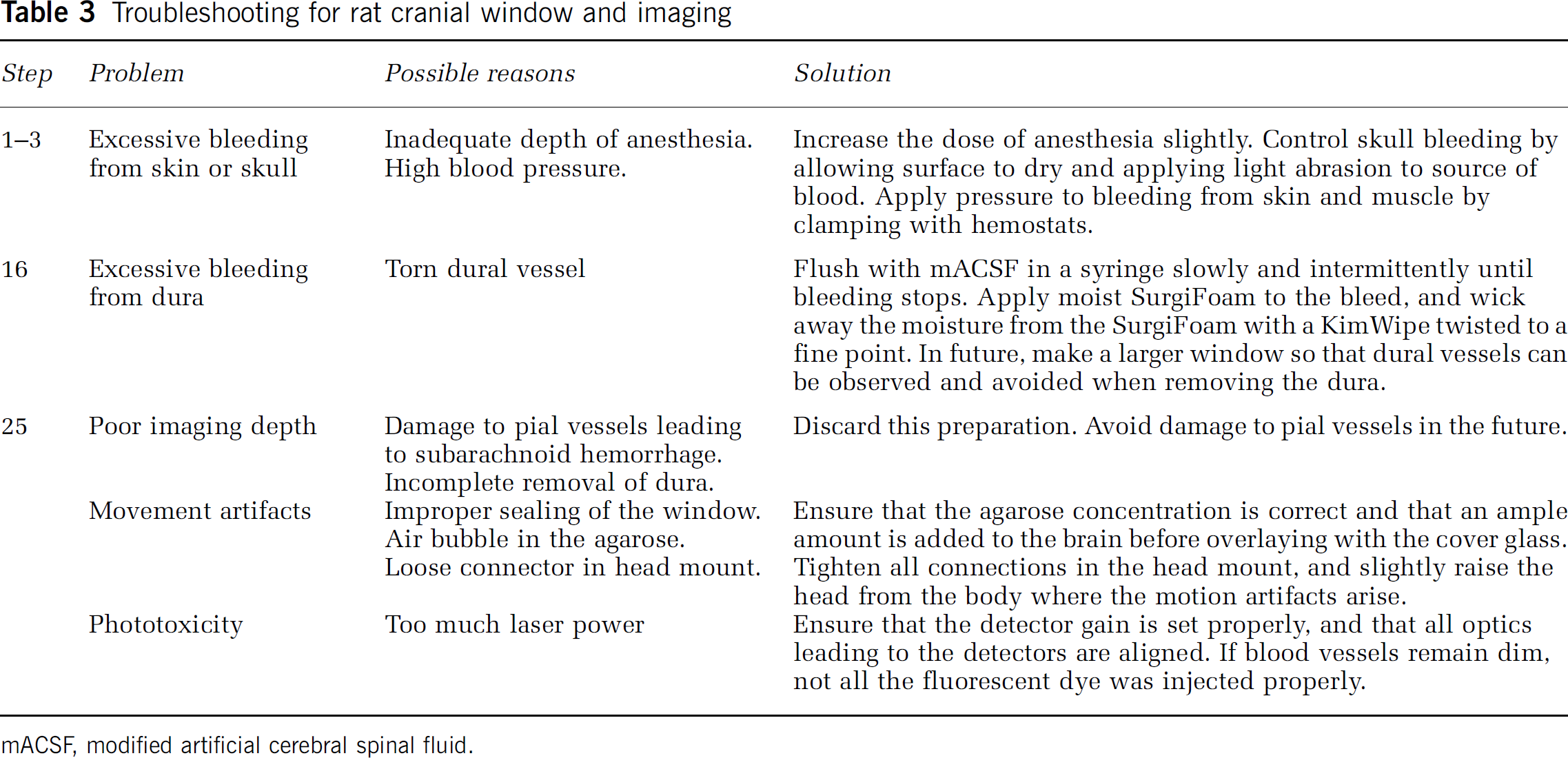
mACSF, modified artificial cerebral spinal fluid.
Chronic Imaging Preparation for Mice: Polished and Reinforced Thinned-Skull Window
This procedure allows repeated imaging for up to 3 months over a large cortical region, i.e., 2 × 2 mm2, without disrupting the intracranial milieu. Imaging depths of up to 250
Remove the scalp over the entire dorsal skull surface (Figure 3A). Use a scalpel blade to remove the thin periosteum from the surface of the skull.
Clean and dry the skull surface. Apply a thin layer of cyanoacrylate glue to the surface and allow the glue to dry thoroughly.
Attach a metal connector to the skull, away from the area of the desired window with a small dab of cyanoacrylate glue and allow the glue to dry thoroughly. Then secure the connector with a layer of dental cement. We adhere a small nut (no. 2-56) that can be later secured to the imaging setup using a bolt (Figures 3B, 3J and 3L). Seal the backside of the nut with tape to ensure that glue does not enter the threads.
Alternatively, attach a custom-made connector, in this case with two attachment points (Figures 3K and 3L). This greatly reduces the degrees of freedom and simplifies relocation of the same imaging field in longitudinal studies. A wide crossbar gives ample room for electrode placement and stimulation of vibrissae.
Cover the rest of the skull surface, excluding the location of the window, with a layer of dental cement (Figures 3C and 3L). Ensure that all exposed edges of the skin are covered by cement.
Stabilize the mouse in a head mount (Figures 3J and 3K). As with the restraint apparatus for rats describe above, a mouse apparatus can be made from commercially available miniature optomechanical components from Qioptiq (Rochester, NY, USA) or ThorLabs (Newton, NJ, USA).
Thin a 2 × 2-mm2 region over the somatosensory cortex with a 1/2-mm burr. Alternate between wetting the skull with mACSF and then drying the skull surface with a gentle stream of air; wet for cooling, and dry for thinning. The skull may bleed from the vessels in the inner cancellous layer, but can be controlled by flushing with mACSF (Figures 3D–3F). The skull begins to flex without breaking under the slight pressure of the drill when it is ∼50
At this point, the bone must be thinned even further, and the speed and sharpness of the drill burr are critical. Change to a new drill burr and lightly shave the skull surface with small controlled movements while holding the drill like a pen. We find that a drill speed of ∼1,000 r.p.m. is appropriate at this stage. Small white spots within the bone, normally visible when moistened bone is ∼50
Polish the window region with tin oxide powder (Figure 3G). Attach a premade drill bit that has been dipped in silicone aquarium sealant and withdrawn, leaving a tapered whip (inset, Figure 3G). Place a small pinch of powder on the window along with a drop of mACSF. Agitate the slurry over the window for up to 10 minutes by gently touching the tip of the moving whip to the skull surface. Surface irregularities and adherent bone chips left by drilling in the previous steps should be removed after polishing. Flush away the tin oxide powder thoroughly from the window using mACSF and dry the bone thoroughly with a gentle stream of air.
Cut small square pieces of no. 0 cover glass, roughly 2 × 2 mm2, by gently scoring separated horizontal and vertical lines in the cover glass with a scribe. Then place the cover glass in a Petri dish and shake vigorously to separate the glass pieces.
Apply a small dab of cyanoacrylate glue over the window using the wooden tip of a broken cotton-tipped applicator and quickly place an appropriately sized piece of no. 0 cover glass atop the glue (Figures 3H and 3M). Using forceps, push the glass so that it is in contact with the skull surface. Avoid creating bubbles underneath the cover glass. Allow the glue to dry thoroughly for 10 minutes before proceeding. Excess cyanoacrylate glue can be removed from the upper surface of the cover glass with a scalpel after it is dried.
Seal the edges of the cover glass with dental cement and form a slightly raised well to hold water for the dipping lens (Figures 3I and 3M).
For some experiments, it may be desirable to inject dyes or insert electrodes into the tissue volume beneath the PoRTS window. A small hole can be added adjacent to the window, through which pipettes or electrodes can be introduced using a stereotaxic arm or Sutter manipulator (Stosiek et al, 2003). This hole can be resealed with bone wax after the experiment if the animal is to be imaged again in future sessions.
Stabilize the animal on an optical breadboard for imaging, using the frame as a head support. Our separate plate can be transported between surgical and imaging suites with the animal and all physiological monitoring devices assembled as one unit (Figures 3J and 3K).
Inject 0.05 mL of 5% (w/v) fluorescent-dextran dye dissolved in saline either through a femoral artery/vein catheter, tail vein, or infraorbital vein to label the blood serum (Table 2). For tail vein or infraorbital injections, use an ultrafine 0.3-mL insulin syringe with a 29.5-G needle.
If the animal is meant to survive for more than 1 day, and is showing clear signs of pain (see step 23 of last section), provide buprenorphine hydrochloride solution subcutaneously for analgesia.
More rigid head mounts are necessary for imaging awake animals. For increased stability, two self-tapping #000 screws can be added to the contralateral hemisphere of the skull before application of the dental cement, as shown in step 3 (Figure 3L).
Habituation to head fixation is important to reduced animal movement during imaging. A new animal can be gradually accustomed to head restraint over a period of 3 to 7 days, starting with 15 minutes sessions and working up to several hours (Drew et al, 2011). Before blood flow imaging, the mouse can be briefly anesthetized with isoflurane for an infraorbital injection of fluorescent-dextran dye. The dye will remain in circulation for several hours, and supplements can be given as necessary if the animal is re-anesthetized.
The cortical vasculature of the mouse is very similar to that of a rat, and can be thought of as a cropped, rather than scaled, version of the rat pial network (Blinder et al, 2010). In our example, we imaged a portion of the pial network after an intravenous injection of Texas red-dextran (Table 2), concurrent with yellow fluorescent protein (YFP)-labeled dendrites in the Thy1-YFP mouse line (Figures 3N and 3O) (Feng et al, 2000; Zhang et al, 2005). The average density of penetrating arterioles, and average surface area occupied by arterioles loops is very similar to the rat, but the total surface area of the mouse cortex is three times smaller (Blinder et al, 2010). As with rat, the subsurface microvasculature is highly tortuous and forms densely packed loops.
Detailed studies from mouse have revealed that neurons lie, on average, 15
Two-photon imaging the vasculature through a PoRTS window requires transmission though the thinned bone and the dura, which attenuates the laser light and adds optical aberrations at greater depths (Drew et al, 2010b). However, despite this drawback, a well-prepared window will allow imaging of depths up to 250
In our hands, the success rate of the PoRTS window can be as high as 80%. In failed cases, the skull is breached or subarachnoid hemorrhaging occurs. These cases should be discarded.
The age of the mouse has a strong influence on the success of bone thinning. In adult mice 4 weeks or older, the rigidity of the more developed skull appears to prevent the bone from breaking, which is necessary to achieve the 10 to 15
For troubleshooting, refer to Table 4.
Troubleshooting for mouse PoRTS window and imaging
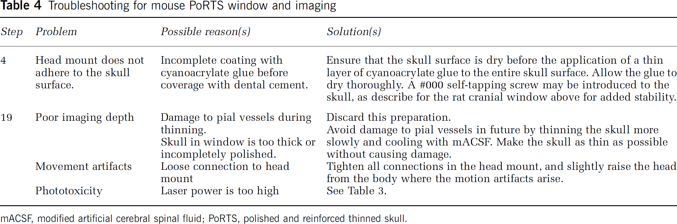
mACSF, modified artificial cerebral spinal fluid; PoRTS, polished and reinforced thinned skull.
Measurement of Blood Flow Dynamics in Single Cortical Vessels
In a typical preparation, we generate a cranial window over the hindlimb and forelimb regions of somatosensory cortex (Figure 4A). In the example given, we image cortical vessels through an acute rat window. Cortical regions that are responsive to stimulation can be mapped with intrinsic optical imaging, which reports a change in the ratio of oxy- to deoxyhemoglobin that occurs secondary to a change in neuronal activity (Frostig et al, 1990; Grinvald et al, 1986). The branching of pial arterioles and venules, which is unique to each animal, serves as useful fiducials to relocate the active region. The preparation is then moved to the TPSLM imaging setup, and the vasculature is labeled with an intravenous bolus of fluorescein-conjugated dextran. The cerebral vasculature within the window is first mapped at low resolution with a × 5 objective (Figure 4A). High-resolution imaging of surface pial vessels, penetrating vessels, and subsurface capillaries can then be performed in smaller regions with a high numerical aperture water dipping objective, such as the LUMPLFL × 40 0.8 numerical aperture objective from Olympus (Center Valley, PA, USA) (Figure 4B).
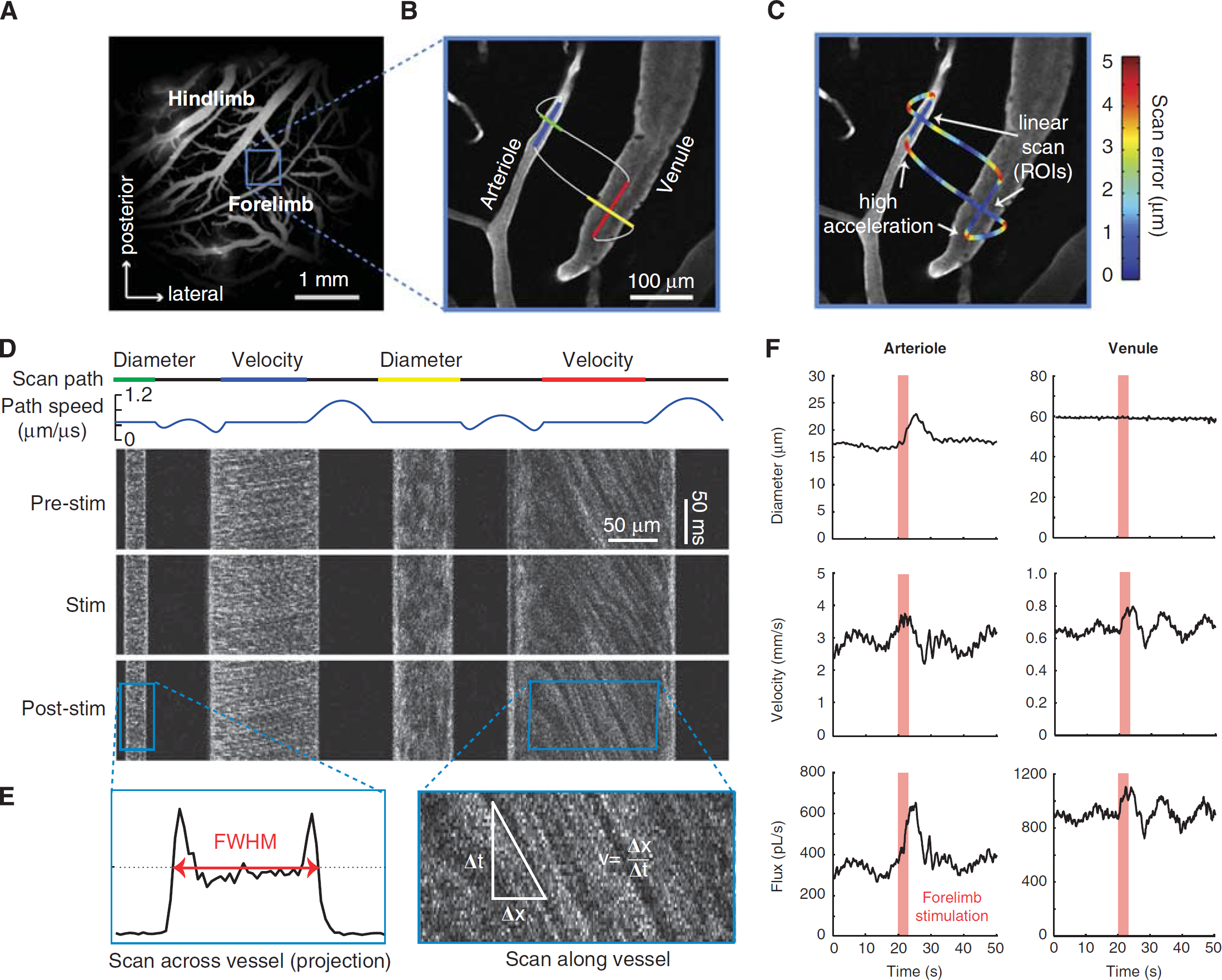
Simultaneous measurement of lumen diameter and red blood cell velocity in multiple vessels using spatially optimized line scans. (
User-Defined Scan Patterns to Simultaneously Measure Red Blood Cell Velocity and Lumen Diameter
When the serum is labeled, RBCs exclude the high-molecular-weight dextran dye and appear as dark shadows moving against a bright fluorescent background. This differential staining is the basis for measuring RBC velocity using laser scanning microscopy (Kleinfeld et al, 1998; Villringer et al, 1989). We used custom software to direct the imaging laser beam in a user-defined path within the imaging plane (Figure 4B;Driscoll et al, 2011a; Valmianski et al, 2010), following earlier work (Göbel and Helmchen, 2007; Göbel et al, 2007; Lillis et al, 2008). Linear segments of constant scan speed traverse along the length of the center of the vessel and across the width of the vessel to measure RBC speed and lumen diameter, respectively. These linear scan segments are connected by polynomial splines, where connecting portions of the scan are accelerated to allow for rapid data collection across multiple vessels (Figure 4C;Driscoll et al, 2011a).
The resulting line scan is a space–time image, typically displayed with the individual scan lines stacked on top of each other (Figure 4D). In principle, many vessels can be measured simultaneously. However, greater distances traversed by the laser will reduce the sampling frequency of RBC velocity, and a 1 to 2 kHz line scan rate is typically required for accurate sampling of the movement of RBCs in pial arterioles (Driscoll et al, 2011a). Further, the RBC speed in penetrating vessels is only measurable when a part of the vessel is parallel to the imaging plane.
Calculating Red Blood Cell Velocity
Portions of the scan path along the centerline of the vessel lumen reveal angled streaks within the cascade image (right panel in Figure 4E). Moving RBCs in flowing vessels sampled at a sufficient rate will appear as diagonal streaks. A stationary or stalled flow will result in vertical streaks. In the limiting case of extremely fast flowing vessels, the streaks will become horizontal, and velocity data cannot be extracted (see also Table 5 for troubleshooting). The centerline velocity is proportional to the slope of the RBC streaks, measured from vertical. Determining this slope is most efficiently performed with a Radon transform of windowed portions of the data (Drew et al, 2010a), which is available in the MATLAB Image Processing Toolbox (Mathworks, Natick, MA, USA). The direction of flow can be extracted from the sign of the slope and the direction of the line scan sweep.
Troubleshooting for blood flow measurement
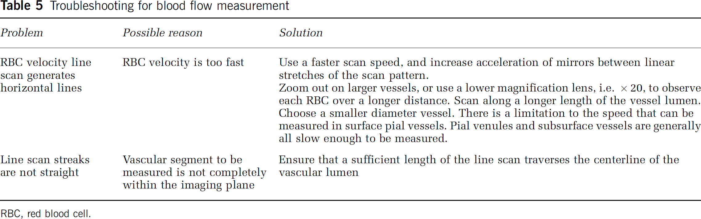
RBC, red blood cell.
A velocity time series is calculated by taking successive time windowed portions of the line scans. The size of the window must be sufficiently short to resolve the highest velocity modulation frequency, the heart rate, which is ∼6 Hz for rats and ∼10 Hz for mice. In addition, the window size must be large enough to capture enough streak lines so that the Radon transform has sufficient data to calculate an accurate velocity value, but small enough to prevent smoothing out the higher frequencies of the velocity data. We find that a window size of 40 ms is a good compromise, which yields a Nyquist frequency of 12.5 Hz. We further use a window spacing of 10 milliseconds.
In addition to heart rate, other physiological signals detected in the RBC velocity of anesthetized rat include breathing at ∼1 Hz and vasomotion at ∼0.1 Hz (Kleinfeld and Mitra, 2011; Mayhew et al, 1996), whereas an awake mouse will have vasomotion ranging from 0.1 to 1 Hz (Drew et al, 2010b); breathing is often not detectable in the awake state (Figure 5;Drew et al, 2011).
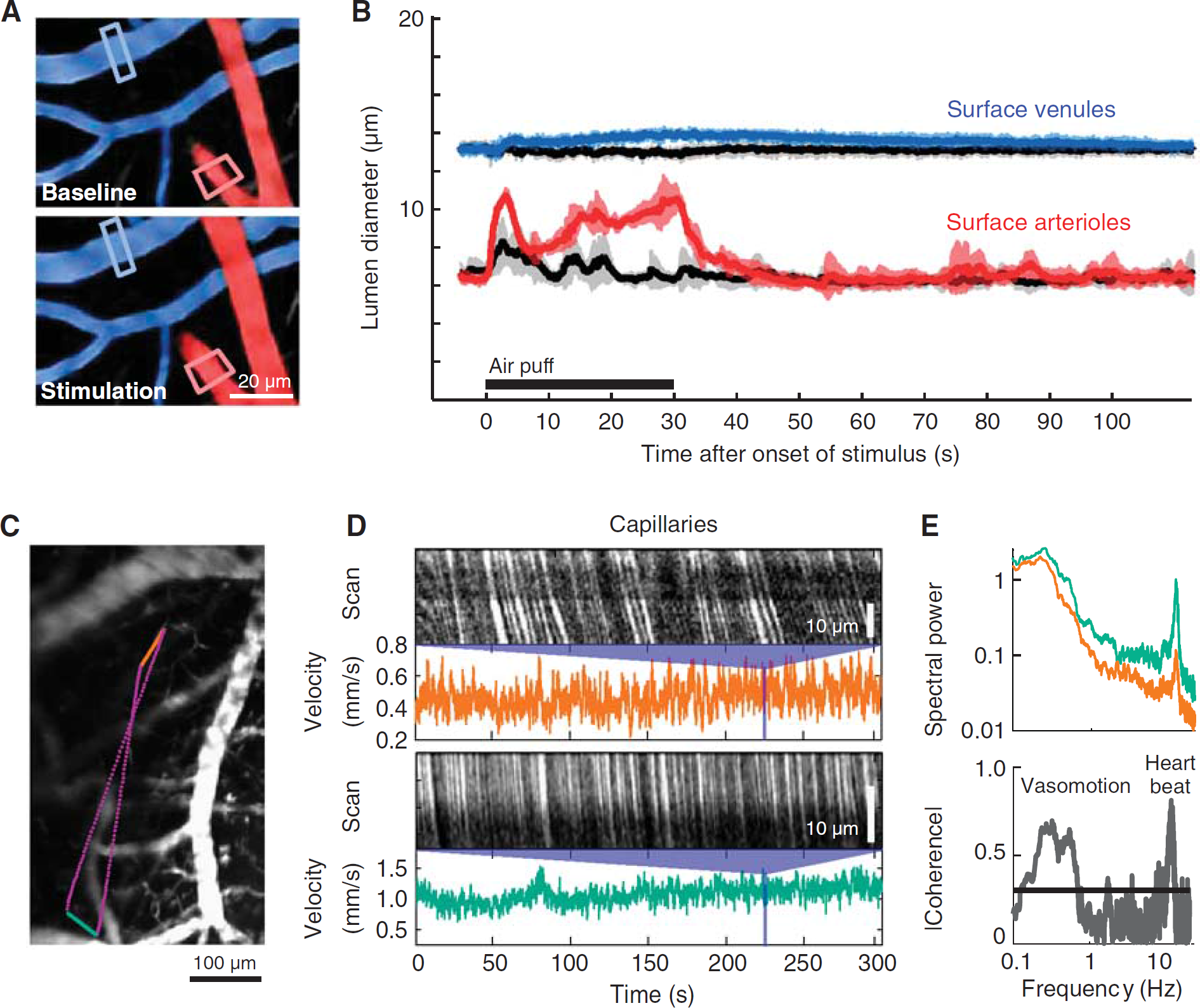
Evoked dilation and basal rhythms of cortical vessels in awake mouse. (
Even when anesthetized, the imaged vessel may move slightly with tissue swelling caused by heart beat, breathing, stimulated increases in blood flow, or edema in stroke models. In practice, most of the movement is within the axial plane. As a quality control measure, velocity line scans can be tested on capillaries, which are only 3 to 5
Maximum Measurable Red Blood Cell Velocity
For relatively fast blood flow, the pattern of fluorescence will change too much to between successive line scans to allow for accurate reconstructions of the flow velocity. As a naive estimate of maximum measurable blood flow velocity, if the RBC diameter is ∼5
Calculating Lumen Diameter
As with the velocity calculation, the diameter calculation is taken from a time windowed portion of the data. The same window size and spacing used for velocity is typically used for diameter so that both parameters can be calculated on the same time scale. Vessel diameter is calculated as full-width at half-maximum of the vessel profile for each window (left panel in Figure 4E). Note the intensity profile tends to increase near the edges because of the exclusion of RBCs from the glycocalyx, which generates two peaks. The two outermost half-maximum points of these peaks are used to calculate the vessel boundary. Linear interpolation is used to add subpixel accuracy to the diameter measurement.
Estimating the Flux of Red Blood Cells
There are two limiting cases for the flux. When the diameter of the vessel allows the passage of RBCs only in single file, as for the case of capillaries, the flux of RBCs is just the number of RBCs that pass per second (Chuquet et al, 2007; Kleinfeld et al, 1998). In this limit, the blood plasma has an essentially constant velocity profile as a function of distance from the center of the vessel, then the velocity falls rapidly to zero near the walls. The thin layer of plasma near the walls acts as a lubricating layer that, together with the glycocalyx, minimizes friction (Secomb et al, 1998).
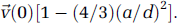
When the diameter of the vessel is much greater than that of the RBC, the flow is laminar and nearly parabolic as RBCs flow in parallel streams (Rovainen et al, 1993; Schaffer et al, 2006). The two vascular parameters, RBC velocity and lumen diameter, are combined to calculate the volume flux, i.e., RBCs and plasma, for each vessel. Flux is a more complete description of blood flow in single vessels, as RBC speed and lumen diameter can change independently of each other (Kontos, 1989; Shih et al, 2009). The volume flux through the vessel is given by
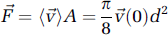
where (
As an example, we measure the change in flux at the level of single penetrating vessels in response to somatosensory stimulation. A line scan frequency of 733 Hz was used to capture the lumen diameter and RBC velocity of an arteriole and a venule nearly simultaneously. Both diameter and RBC velocity in the arteriole respond to stimulation (left column in Figure 4F). The flux through the arteriole increases to a peak of 86% over baseline, compared with a much smaller peak increase of 29% and 24% for diameter and velocity measurements alone, respectively. The increase in RBC velocity is partially masked by a peak in the underlying vasomotor fluctuation, but remains a significant increase over an average 1-minute period of basal activity.
In contrast to the arteriole, a neighboring venule exhibits no change in lumen diameter, but a 23% change in RBC velocity. As a result, the flux increases in the venule by 23% as well (right column in Figure 4F). This increase in venular flux would not be detected with methods that measure diameter only. This caveat should also be kept in mind with arterioles, as functionally evoked diameter changes may not occur along the entire length of the vascular tree. Changes in RBC velocity, however, will be detectable both upstream and downstream of the point of resistance change.
Similarly, the underlying vasomotor oscillation exists only in the RBC velocity traces for each vessel, likely because changes in resistance are occurring upstream of the measured vessel segments. Vasomotion is also commonly observed as slow changes in arteriole diameter (Lefer et al, 1990; Ngai et al, 1995). Here the amplitude of the vasomotion oscillations in the venular RBC velocity trace increases after stimulation, consistent with previous findings (Figure 4F;Vetri et al, 2007).
Example applications
Imaging Stimulated and Basal Hemodynamics in Awake Mice
Cortical vascular dynamics are profoundly different in the awake vs. anesthetized states (Martin et al, 2006). Anesthetics are known to reduce the functional hyperemia response (Lindauer et al, 1993) and also slow vasomotor oscillations (Drew et al, 2011). Here, we show the quantification of blood flow both at and below the cortical surface in awake mice (Figure 5). Mice were habituated to head fixation and blood flow was measured in single vessels through a chronically implanted PoRTS window. Robust arteriole dilations could be evoked by prolonged contralateral whisker stimulation (Figures 5A and 5B, red). Pial venules, typically thought to be static in terms of diameter, show a delayed and weak dilation in the awake state (Figures 5A and 5B, blue). Both arteriolar and venular responses were strongly suppressed by the use of urethane, a common anesthetic (Drew et al, 2011). These data suggest that functional hyperemia changes detected by BOLD fMRI may be dominated by large changes in arteriole volume, in agreement with recent studies (Kim and Kim, 2011), rather than in venules as predicted by the ‘balloon’ model (Buxton et al, 1998).
Dilatory events are relatively slow and diameter measurements can be analyzed from full-frame movies collected at six or more frames per second, in addition to line scans. Measurement of RBC velocity in subsurface capillaries always requires rapid line scanning to accurately quantify (Figures 5C and 5D). We create a user-defined scan path across two capillaries separated by a 500
Simultaneous Imaging of Blood Flow and Local Cellular Activity During Neurovascular Coupling in Anesthetized Rat
An important goal is to identify the cell types and signaling pathways that regulate neurovascular coupling. The activity of various neuronal cell types and astrocytes can be monitored in superficial cortex by bulk loading the tissue with functional dyes, in this case Oregon green bapta-1-AM, to detect changes in [Ca2+]int (Garaschuk et al, 2006; Stosiek et al, 2003; Figure 6A). The Ca2+ indicators may be injected by micropipette into the active region through a vent in the cranial window under two-photon guidance (Figure 2M) or before sealing the window during the initial craniotomy procedure.
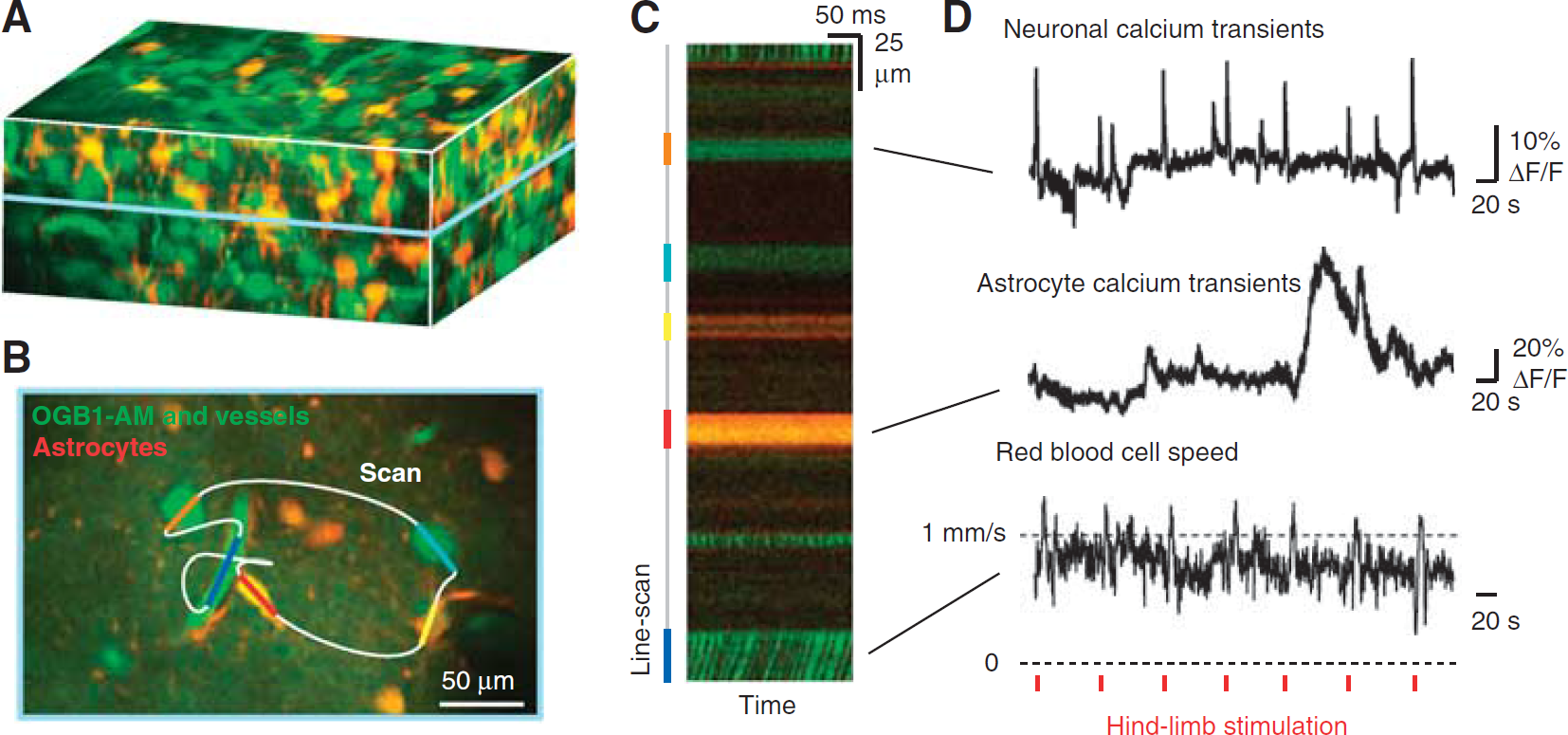
User-defined scan pathways to simultaneously record blood flow and activity from neighboring cells. (
User-defined line scans are used to measure the activity of neurons and astrocytes concurrent with blood flow in a neighboring microvessel through the cranial window of an
The approach described here allows one to correlate the specific location and activity of defined cell types with local changes in blood flow. Transgenic mice with different neuronal subtypes labeled with fluorescent proteins may aid the separation of responses from different cell populations (Sohya et al, 2007). Finally, genetically encoded [Ca2+]int sensors exclusively expressed in a specific cell type can be essential in separating signals from individual cells, which may be an issue with bulk loading of all cellular compartments (Shigetomi et al, 2010; Tian et al, 2009).
Measurement of Arteriolar Smooth Muscle Function
Techniques to measure activity in arterial smooth muscle are critical for understanding the vasoactive signals that lead to functional hyperemia. The combined action of vasoactive transmitters released from all local cells, astrocytic or neuronal in origin, eventually translate into a contraction or relaxation of arteriole smooth muscle. Elevation of cytosolic [Ca2+]int is the major determinant of smooth muscle contractility (Karaki et al, 1997).
The observation of smooth muscle [Ca2+]int dynamics
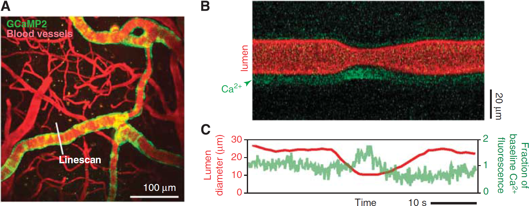
Measurement of arteriole smooth muscle activity concomitant with vasodynamics. (
Imaging of Blood Flow in Deep Cortical Layers
An important development in TPLSM is the ability to image deep cortical layers that are responsible for the output of neuronal processing (Helmchen and Denk, 2005). Penetrating arterioles are separated from the tissue by the fluid-filled Virchow-Robin space. As the penetrating arteriole plunges deep into cortex, the vascular adventitia fuses with the glial limitans, forming a close association between the cortical parenchyma and the vasculature. It is at this close point of interaction that neurovascular coupling is likely to initiate (Hamel, 2006).
Longer wavelengths of light penetrate deeper into tissue as a result of reduced scattering, absorption, and optical aberration. In this example, excitation with 1,280 nm wavelength light from a Ti:sapphire-pumped optical parametric oscillator enabled TPLSM imaging through the entire depth of mouse cortex, i.e., over 1 mm deep, through a dura-intact cranial window (Figure 8A;Holtmaat et al, 2009; Kobat et al, 2009). Red blood cell velocities in capillaries could be resolved as deep as 900
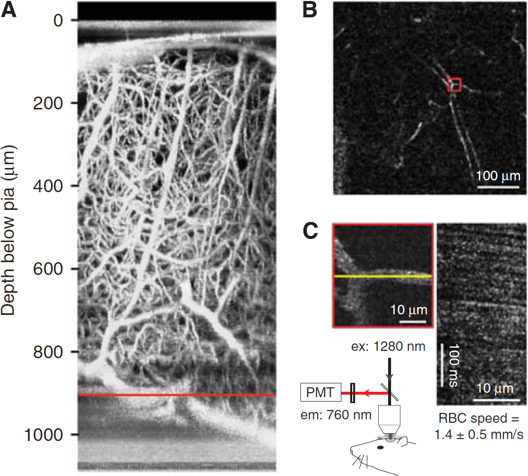
Deep imaging of cortical angioarchitecture and blood flow. (
Measuring Partial Pressure of O2 in Blood Vessels and Tissue
A critical determinant of neuronal metabolic activity is the availability of O2 supplied through the blood. Further, a feedback mechanism may exist, as ambient pO2 levels also influence the dilatory capacity of cerebral arterioles (Gordon et al, 2008). The mechanisms that govern pO2 in brain tissue are not well understood. In recent work, a small molecule pO2 probe, Ptp-C343, was developed and imaged with an optimized TPLSM setup (Finikova et al, 2008; Sakadzić et al, 2010). Subsequent to two-photon excitation, the probe decays by phosphorescence—a process that is accelerated when the O2 tension is high. The partial pressure of oxygen, pO2, can then be calculated offline by fitting the phosphorescence decay to an established calibration curve.
The probe enables measurement of absolute pO2 concentration either within the vascular lumen following intravenous injection or the cortical parenchyma following intracerebral injection. The example of Figure 9 shows how pO2 can be measured at the level of single vessels through a dura-intact cranial window in mouse, after intravenous delivery of the probe. The vascular architecture was first determined by conventional imaging with fluorescein-dextran (Figure 9A). The Ptp-C343 phosphorescence originating from the lumen of a single penetrating arteriole and penetrating venule was then sampled at ∼150
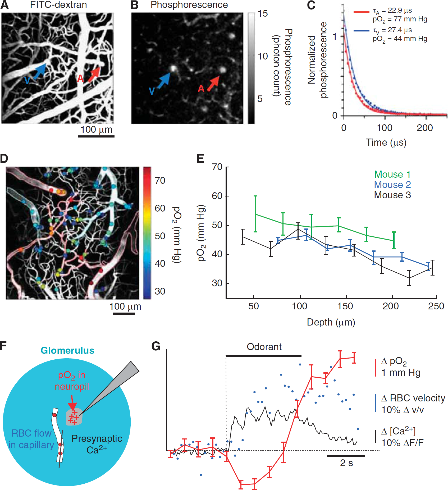
Imaging of intravascular partial pressure of oxygen. The mouse cerebral vasculature was imaged through a dura-intact cranial window following intravenous delivery of the phosphorescent O2 probe PtP-C343. (
Combined with the TPLSM blood flow measurement techniques, we have described (Figure 4) small molecule O2 probes will aid the study of O2 transfer from vasculature to tissue during functional hyperemia during health and various disease states (Girouard and Iadecola, 2006). Indeed, Lecoq et al (2011) has elegantly demonstrated the feasibility of measuring cerebral blood flux, neuronal activity, and pO2 simultaneously in olfactory bulb (Figures 9F and 9G). Recent work by Devor et al, (2011) has extended similar measurements to the superficial layers of cortex.
Manipulating Blood Flow with Photothrombosis and Laser Ablation of Single Vessels
The majority of current preclinical stroke models focus on large-scale ischemic strokes that manifest severe behavioral deficits (Ginsberg and Busto, 1989). However, small cortical infarcts are prominent in cases of human small vessel disease and dementia, and are clinically difficult to detect (Kövari et al, 2007; Suter et al, 2002). Optical access to the vasculature offers the opportunity for laser-mediated formation of intravascular clots in single vessels, as a model to study the effects of small-scale stroke in rats and mice (Hua and Walz, 2006; Mohajerani et al, 2011; Nishimura et al, 2006, 2007). On the cortical surface, single vessel thrombosis is achieved by irradiating the lumen of the target vessel with a focused green laser to activate the circulating photosensitizing dye, Rose Bengal (Schaffer et al, 2006; Watson et al, 1985). Below the cortical surface, thrombosis is achieved by focusing high-fluence, 100 to 300-fs pulses of near infrared light into the vessel lumen (Nishimura et al, 2006). Nonlinear absorption ensures that the laser injury is limited only to the plane of focus. In both cases, damage of the vessel wall induces clot formation in the lumen.
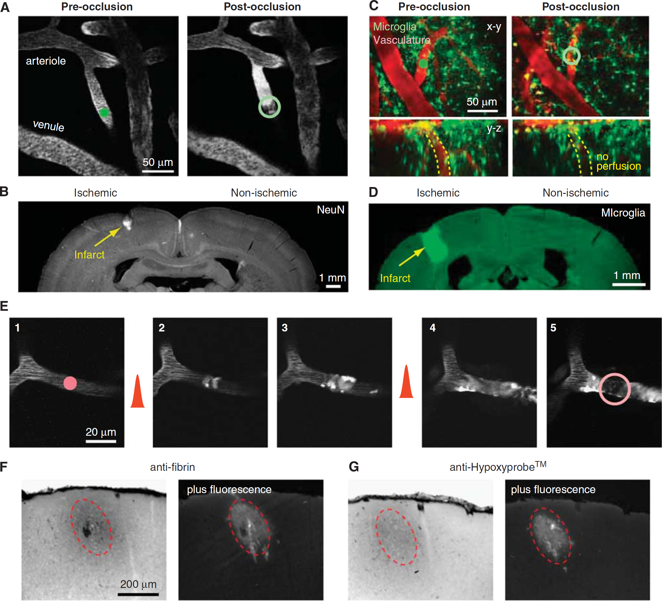
In the first example, we use Rose Bengal irradiation to occlude one of many penetrating arterioles visible on the pial surface through a dura-removed cranial window in rat (Figure 10A) or a PoRTS window in a CX(3)CR1 transgenic mouse with green fluorescent protein (GFP)-labeled microglia (Figure 10C). Measurements of blood flow can be made before and after the occlusion, to confirm successful occlusion and to examine adaptive flow changes in neighboring vessels (Nishimura et al, 2010; Schaffer et al, 2006). One week after occlusion, a localized cortical infarct can be identified by immunostaining for the pan-neuronal marker NeuN (Figure 10B) or by aggregation of immune cells in the infarcted tissue (Figure 10D), consistent with the concept that penetrating arterioles form bottlenecks within the cortical vasculature (Blinder et al, 2010; Nishimura et al, 2007).
Manipulation of blood flow in single-cortical vessels using auxiliary lasers. (
In the second example, we consider a microvessel that is 10
Finally, longitudinal
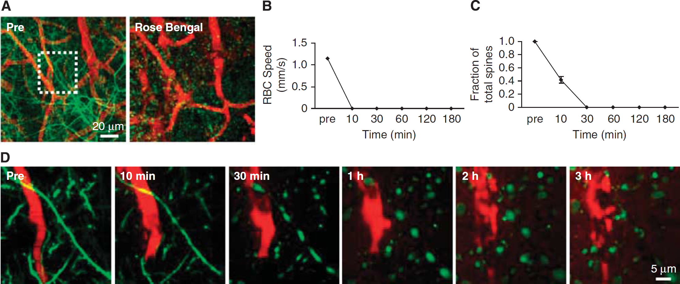
Imaging of neuronal structure following targeted stroke. (
Summary and future steps
Two-photon microscopy provides a number of advantages that will aid the study of the mechanisms underlying neurovascular coupling and cerebrovascular disease in animal models, including: (i) the resolution needed to visualize single cortical vessels and their surrounding cells; (ii) penetration depths of 250
A wide variety of functional fluorescent dyes that currently exist can be exploited for studies of neurovascular control. Recent focus has been on Ca2+ sensors to study cellular activity. Organic-based sensors such as OGB1-AM have the advantages of labeling both neurons and astrocytes, along with a meshwork of processes that intervene between cell bodies. However, the cellular source of a signal may be difficult to resolve when focusing on fine processes. Genetically encoded Ca2+ sensors that are expressed only in specific target cell populations will resolve any ambiguities of signal source. Cyclic adenosine monophosphate sensors would also be of value considering that Ca2+-independent pathways may also be involved in neurovascular control.
Similarly, the intermixing of cell types within a small tissue volume also hinders electrophysiological and pharmacological approaches to query the role of cell types in neurovascular coupling. New advances with light activated opsins (Lee et al, 2010) or engineered receptors with unnatural affinities for exogenous chemicals (Alexander et al, 2009; Fiacco et al, 2007) may help to unravel issues with cellular specificity (Kleinfeld et al, 2011). However, caveats should also be considered, as activation of one cell type does not preclude activation of nontargeted cells linked within the same circuitry. To test for specificity of action, opsins could be used in conjunction with bolus-loaded Ca2+ sensors (Figure 6) that report the activity of surrounding cells. Another approach would be to inhibit critical signaling pathways. The manipulation of cell-specific vasoactive signaling cascades will be an important step in dissecting the chemical basis of neurovascular coupling, but will also be the most challenging as new tools to knockdown gene expression will need to be developed (Kleinfeld et al, 2011).
There is also an additional need for tools to quantify volume conduction of vasoactive transmitters concurrent with measurement of blood flow. We recently described the use of CNiFERS, HEK293 cells that co-express the genetically encoded Ca2+ sensor TN-XXL with a muscarinic acetylcholine receptor. Following implantation directly into cortex, CNiFERS enable real-time measurement of extracellular acetylcholine concentration (Nguyen et al, 2010). Further, injectable protein-based detectors of neurotransmitter concentration, such as the EOS glutamate sensor, may be useful for studying vasoactive signaling (Okubo et al, 2010).
Future imaging studies related to neurovascular control are likely to make exclusive use of awake, behaving mice to circumvent problems associated with anesthesia, such as suppressed autoregulation (Drew et al, 2011). Genetically encoded indicators of physiological function as well as methods to optically stimulate cellular activity and specific signaling pathways are well suited for studies in awake, behaving mice (Airan et al, 2009; Drew et al, 2010b; Zhang et al, 2007).
We have described methods that can be used to observe and manipulate the fine-scale of neurovascular coupling, i.e., at the interface between cells and vasculature. However, it is important to realize that the somatosensory-evoked hemodynamic response extends deep into the tissue as well as laterally across cortex, and involves considerable trial-to-trial variability (Drew et al, 2011). A full understanding of the response requires the ability to quantify flow from hundreds of vessels within a large volume of tissue. This represents an important challenge, as TPLSM is pushed to its limits in imaging depth (Helmchen and Denk, 2005; Kobat et al, 2009; Oheim et al, 2001; Theer et al, 2003; Theer and Denk, 2006) and line scanning speed (Göbel and Helmchen, 2007; Göbel et al, 2007; Lillis et al, 2008; Valmianski et al, 2010). Currently with TPLSM, long imaging sessions are needed to measure over a large population of distantly located vessels, and measurements would not be obtained simultaneously. Even with the user-defined line scan capability demonstrated here (Figure 4), the imaging of cellular activity and vascular response is limited to closely associated cells and vessels that lie in the same imaging plane. New tools that enable rapid shifting of the focal plane could extend the capability of the techniques discussed here. These include: (i) pairs of acoustic-optic deflectors to both scan the laser beam in the
Although not permitting the true three-dimensional line scanning just described, techniques to more slowly shift the focal plane with piezoelectrically actuated microscope objective mounts (Göbel et al, 2007), or to sample multiple focal planes simultaneously by multiplexing the imaging beam (Carriles et al, 2008; Cheng et al, 2011) offer the capability to acquire data at multiple cortical depths in rapid succession. Further, evolving techniques such as Doppler optical coherence microscopy (Srinivasan et al, 2011) and photoacoustic microscopy (Hu and Wang, 2010), may become more suitable for studying the hemodynamic process over broader areas of cortex while maintaining single vessel resolution.
Limitations to imaging of deep structures in cortex may be overcome with longer wavelength and improved photon collection (Kobat et al, 2009), or the use of microprisms (Levene et al, 2004). However, observation of flow in white matter and subcortical structures, which lie more than 1 mm below the brain surface in mice, require the removal of a column of cortical tissue (Dombeck et al, 2010). Microendoscopic methods using GRIN lenses allow stable imaging for weeks after the placement of a glass guide cannula through the cortex (Barretto et al, 2009). This approach would be of particular interested when studying small vessel diseases that afflict deeper brain structures, such as subcortical lacunar stroke and leukoariosis.
Footnotes
Acknowledgements
The authors thank to Pablo Blinder, David A Boas, Timothy H Murphy, Sava Sakadžiæ and Serge Chapak for generously contributing artwork and images. We also thank Celine Mateo for critical reading of the manuscript.
Disclosure/conflict of interest
The authors declare no conflict of interest.