
Abstract
This article describes device integration with an emerging standard in laboratory automation. The architecture of a library is described, which offers smart adaptation to the standard and a smooth integration into a laboratory automation environment. The library has a plugin interface to allow making any device standard compliant. It allows the use on embedded hardware, and it supports its use with different programming languages. With a tiny starter application, the library can be used as a stand-alone application, and it can be started out of an existing device controller.
Introduction
In a laboratory automation environment, integrators set up their automated laboratory by a setup of several devices of different vendors. Such a device is used to accomplish a task—whether a preparation step, such as diluting, or an analyzing step, such as an absorbance measurement—with a microplate or only a separate substance. Each chosen device is selected carefully to best fulfill the requirements of the laboratory, such as processing rate or accuracy. To be most flexible during the integration, the device vendors equip their devices with established PC interfaces, such as USB, RS232, or Ethernet. Figure 1 shows how a central process management system (PMS) connects to such devices.
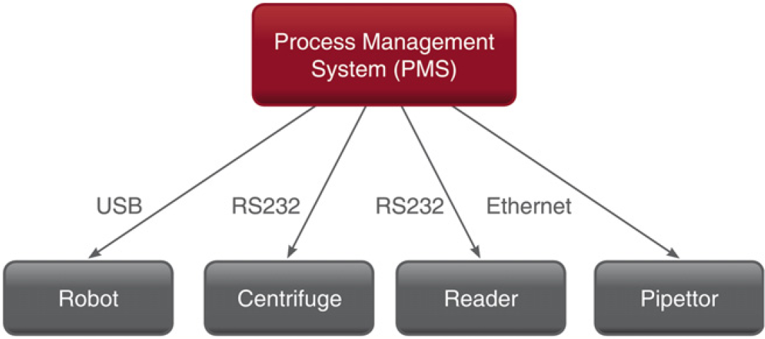
Example setup of a laboratory automation environment.
A PMS allows an operator to create a flow of steps that has to be performed for defined microplates. Such a workflow might start to fetch the correct microplate with a robot and move it to a dispenser. There, the substances in all wells shall be diluted. Then, the robot shall move the plate to a plate reader, which performs some absorbance measurements and produces some results, which an operator or a researcher can use to draw conclusions about the substance. The task of the PMS is to schedule the required steps as time efficient as possible with many microplates.
The devices might be from different vendors. However, each vendor offers a unique interface. So the integrator has to realize a driver for every device in use. Even devices of the same class, such as dispenser, offer different interfaces depending on the vendor they are produced by.
By using a standard protocol, all can profit. Suppliers do not need to create a protocol for their devices because the standard already describes it. Additionally, the penetration of the market is easier because the standard functionality can be used by every PMS that supports it. The integrators can offer solutions more rapidly with the standard because they do not need to handle drivers that are totally different for similar devices. From this time efficiency, the applier also benefits.
We provide a solution ready to use for both devices and PMS to apply a standard. The solution consists of two libraries, one for the PMS and one for the devices. This article focuses on the library for the devices.
The next chapter provides related solutions. Then an overview about Standardization in Lab Automation (SiLA) gives some background knowledge about the standard. A section about the software architecture describes the design that is based on the decisions of the standard. Afterward, working solutions realized with the library explained in this article are described. Finally, an outlook is given.
Ways to Support Device Integration
Laboratory Rapid Automation Toolkit 1 realizes a peer-to-peer communication to address the modularity that could be reached with devices, but which a central PMS stands in the way. Alas it is based on a standard that did not achieve broad acceptance and that standard was not even followed exactly.
Open Lab Automation 2 is an open source approach. Device drivers, which are developed for any integration project, will be made available as open source to the community. The companies creating and using such drivers potentially compete with each other. Therefore, certain reservations exist in providing drivers to others.
We chose to create a commercial library that strictly follows a standard. Standards that match our intention are SiLA 3,4 and Laboratory Equipment Control Interface Specification. 5 For the latter one, no relevant usage is known. Other standards have a different focus, so we decided for SiLA. The next section gives an introduction to that standard.
Standardization in Lab Automation
SiLA is an open standard that specifies the communication between a PMS and its devices. No licensing fee is foreseen for implementers and users; they only have to buy the specifications. The next section describes the technique SiLA specified for the communication to the devices over web services. Afterward, a short introduction into the state machines of the devices is provided.
Communication over Web Services
The SiLA communication takes place over Ethernet and is based on web services. It is in the nature of processes taking place in devices, such as a centrifuge or a reader, to take some time for the execution. Therefore, the command execution is done asynchronously by means of events. A typical hypertext transfer protocol connection is not designed for asynchronous events, so the PMS also has to start a web service. Figure 2 shows a communication diagram for a typical command execution between a PMS and one device.
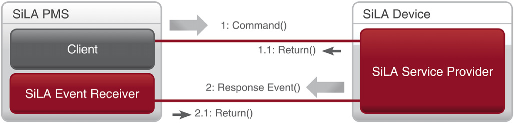
Asynchronous command invocation.
The diagram shows the PMS calling a command of a device (1). The command is acknowledged by a synchronous response (1.1) indicating that a process at device site has been started. After the process finished, a response event is sent (2) from the device to the event receiver of the PMS. The response event can include result data, such as an entire plate report. Finally, the response event is acknowledged (2.1) by the SiLA Event Receiver.
Device State Machine
To guarantee a common behavior of the devices, SiLA specifies three state machines, which all devices have to follow. During the device initialization or when the device is idle, only the first state machine is needed. Figure 3 shows an object diagram with an instance in 3a for the main state machine. When one command is started (3b), two further state machines are instantiated. The main tasks of the Asynch Processing State Machine are pause handling and event sending. The tasks of the Busy State Machine can best be seen in Figure 3c, which applies for two commands being executed in parallel. That case shows that for each command an individual Asynch Processing State Machine is instantiated. So the Busy State Machine manages the creation and disposure of Asynch Processing State Machines. This includes parallel execution and queuing. Within each state, machine transitions correspond to the commands that can be issued on the device.
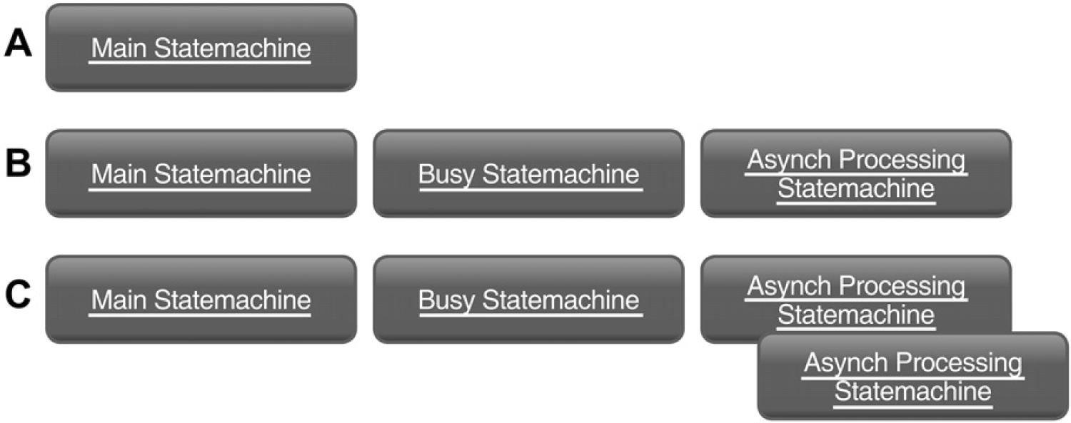
State machines execute (A) no, (B) one, and (C) two device controlling commands.
Software Architecture
To prepare for the emerging standard, we realized two libraries. One offers a simple software interface for a PMS to use a SiLA-compliant device. The other library offers a ready-to-use SiLA interface to make devices SiLA compliant. This article focuses on the latter; it will be discussed in the following sections.
To decide on the architecture, some general deployment information and design goals need to be discussed. We planned two different approaches for the deployment of the library. On the one hand, a converter can be created with a SiLA interface on the one site and a proprietary interface on the other site. In that case, a stand-alone application needs to be built. Legacy devices can use such a converter. It may be installed on a separate computer or on the PMS computer. On the other hand, a library shall be provided that can be controlled from an existing application. Such a library may be used by newly created devices or by devices with existing driver software. The main design goals for the software are the support of the deployment scenarios as described above, the use on embedded hardware, and the combinability with C# code.
We decided to create a library with plugin interface. Such a library can be used by existing software or by a tiny starter application. The next sections describe this library. First, an overview is given including a class diagram, which shows the main modules of the library. Afterward, separate sections discuss the different modules in detail. Finally, the device integration is discussed.
Architecture Overview
As the library needs to support the use on embedded hardware and the integration into existing software, we decided for the language C/C++. The combination with device drivers in other programming languages, such as C#, is possible and in use in customer projects. We decided not to rely on any open-source library because of legal issues, so we had to realize even basic functionality from scratch. The library has to offer a web service that accepts and acknowledges the commands, asynchronously starts a process, and finally sends a response event. Figure 4 shows the main modules of the library. The following sections give a brief overview over the respective projects.
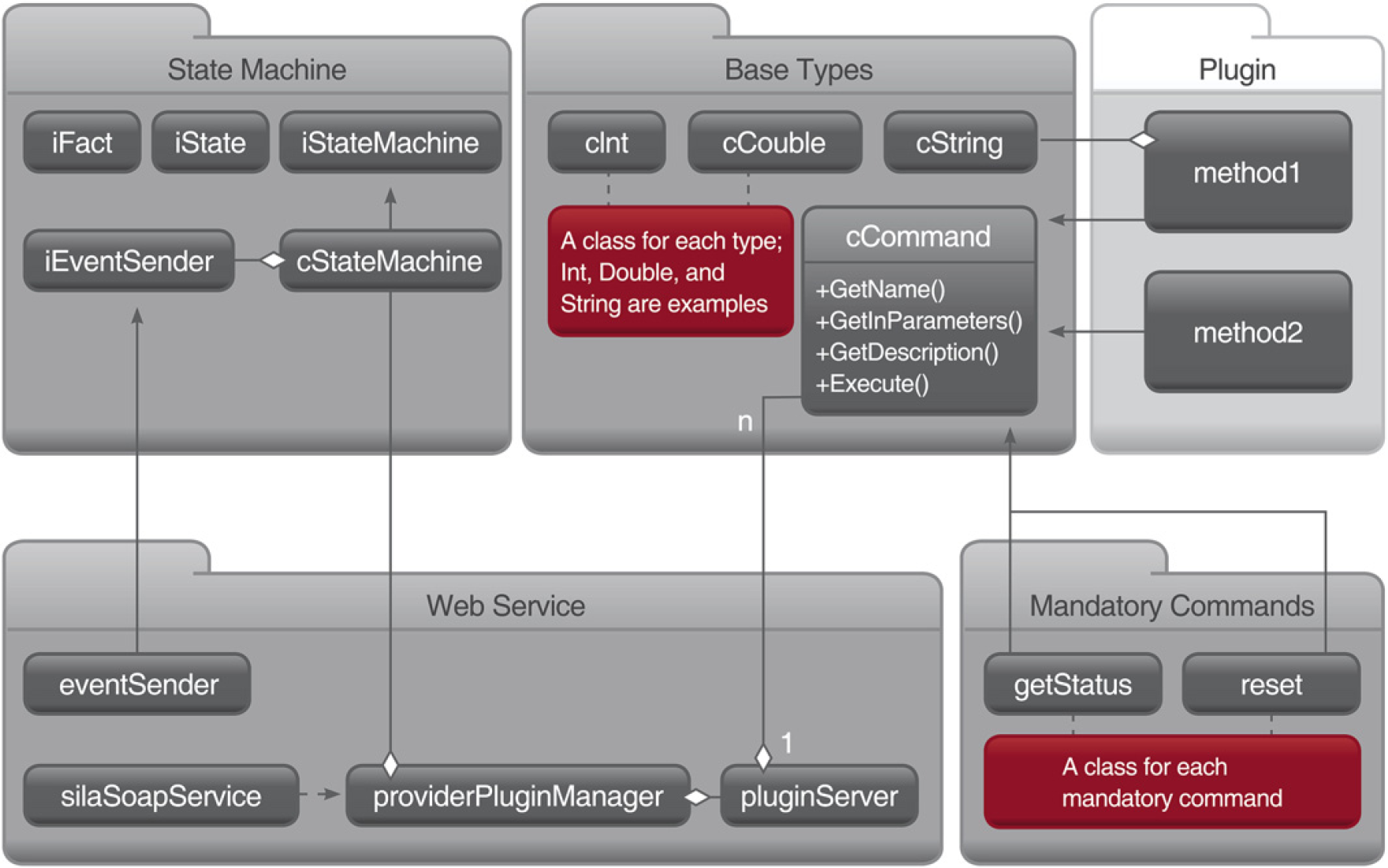
Library's main modules, classes, and dependencies.
Base Types
The project Base Types is located in the center at the top of Figure 4. It defines simple and complex types, which are used by SiLA. Instances of these types can be created with string values, which are received by a web service request; a “3” as American Standard Code for Information Interchange value will be contained in the web service request to describe the integer value 3. The types can also serialize themselves for web service responses or the response event. The classes can be serialized to describe the web service or for the SiLA annotation extension, which allows adding ranges and default values to parameters.
Additionally, the base class for commands is located in this project. The class cCommand defines what needs to be specified for a command. A command basically consists of a name, parameter list, and return value. Therefore, the types described above can be used.
Mandatory Commands
The project Mandatory Commands contains a class for each mandatory command—a command that controls the SiLA state machines. This also includes SiLA events, such as the data event, which can be sent to provide intermediate data. They each represent the data a SiLA command has to provide, especially for the annotation extension, such as a describing text, specification of parameter, or flag that indicates a SiLA-specific command classification. To specify all the data required for a parameter, the Base Types are used.
State Machine
State Machine implements the required behavior according to the three state machine diagrams specified by SiLA. This includes the asynchronous command execution, the state changes, parallelism, and queuing. The backbone of the entire project consists of the three classes iFact, iState, and iStateMachine. As the name suggests, each derivation of iState represents a state within a state machine. Each state realization holds a list of allowed transitions and their transition conditions to provide the state machines with this information. The state machine then can generically check whether a command is allowed and which state it can lead to. Each derivation of iFact represents a fact that occurred, such as the reset fact represents the information that Reset has been called. Additionally, the facts transport information that will be needed to control the device, such as the parameters of the command call.
To represent the three state machine diagrams of SiLA, there are three derivations of iStateMachine. Each provides the method Happen that accepts facts and handles them. In case of a plugin call, the state is switched to the appropriate state, and a thread for the command execution will be started.
Web Service
The web service realization enables to start up a web service and receive web service messages. These messages are forwarded to the state machine to handle their execution. Additionally, this project handles loading plugins, which represent the device control. To allow immediate reaction of the web service, different threads handle the communication. Figure 5 shows the first thread as a circle at the left. It accepts web service requests, checks whether they are syntactically correct, and puts them into either a queue for mandatory commands or a queue for other plugin commands. Afterward, it notifies another thread to read the commands from the queues; the queue for mandatory commands is handled with higher priority because plugin commands might need to be aborted or paused by the according mandatory command. Finally, the commands are forwarded to the state machine as fact. In addition to the immediate reaction, this procedure guarantees a single-threaded entry to the state machine.
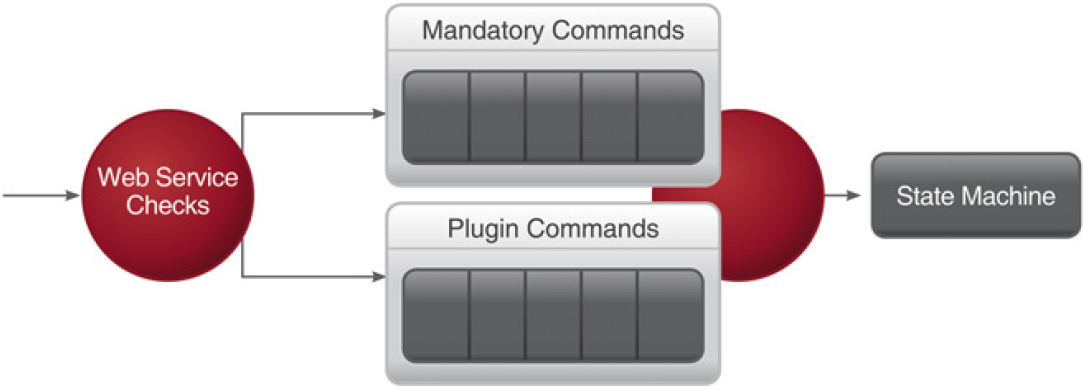
Threads and queues of module web service.
Device Integration
To integrate a device, the device's functionality has to be provided by SiLA commands. The efforts for controlling the device, such as realizing proprietary RS232 commands, will not be reduced by any library. However, once this realization exists and is broken down into the individual commands, the infoteam SiLA Library allows a rapid integration of the device. Therefore, three things need to be created: The command realizations, which make up the plugin, a configuration file, and a starter of the application. The configuration file contains the filename of the plugin and some network information.
Figure 6 shows the method Initialize in the class silaSoapService. The starter of the application, the class ApplicationStarter, calls this method, which creates the libraries' queues and threads. Then, the method Run is started, which uses the thread of the caller to run the web service. The method Run will not return on its own, but the web service can be stopped by other methods of silaSoapService. This approach can be used by both, a converter application, such as a windows service, or an existing device driver.
The other three classes of the Device Driver (PluginSettings, Reset, and AspirateFromSource) make up the command realizations. In this example, the SiLA commands AspirateFromSource and Reset are propagated to the device. Reset is a mandatory command, 3 so it derives from cMandatoryCommand. This method specifies the methods that can be overwritten. Both GetTiming commands are used from the library to provide a SiLA compliant time estimation for the PMS. This duration depends on the tasks the device has to perform during the execution of Reset. The execution is done in the method Execute. The method GetEventSender can be used to retrieve an object that allows sending SiLA events, such as the previously mentioned data event. The command AspirateFromSource is no mandatory command, 3 so it derives from cCommand. Commands that are no mandatory commands are not already defined in the SiLA specification, so additional information has to be provided. The method GetName has to return the name of the command: “AspirateFromSource.” The methods GetInParameters and GetOutParameters specify the parameters of the web service, including ranges and default values. The method GetDescription provides a description of the command for the annotation extension. The PluginSettings provides methods that register the classes, which represent the methods.
In the example in Figure 6, only one Mandatory command is realized. The other mandatory commands will be available automatically in the web service, and they all will control the state machine as specified. There is only no communication to the device during their execution.
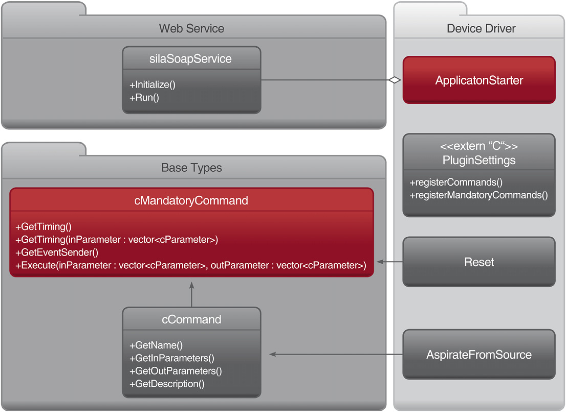
Integration of a device driver.
There are different ways to integrate a device using the infoteam SiLA Library. For legacy devices, the library can be used to provide a converter box. This converter box offers a SiLA/Ethernet interface for the connection with the PMS and a proprietary interface to connect to the device. In this case, the ApplicationStarter can be started as a stand-alone application.
If there is already a software controlling the device, which does not offer a SiLA interface yet, our library can be integrated in that software. In this case, a separate thread will start the web service.
Proof of Concept
Besides customer projects, which are still in progress, we used the infoteam SiLA Library to realize different exhibition exponents. On the MipTec trade show 2009, we presented the device drivers for a Tecan Sunrise Reader and a Thermo Scientific Multidrop Dispenser compliant to SiLA 1.0. The Reader was lacking a reading module. Figure 7 shows that the converter box that allows controlling these devices is an embedded device.
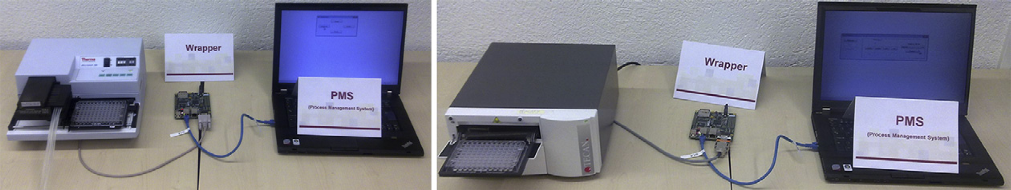
SiLA converter box for a dispenser and a reader.
On the MipTec trade show 2010, we used the infoteam SiLA Library to visualize a SiLA 1.1 compliant state machine. It highlights its internal state—first state machine only. Figure 8 shows a screenshot of the visualization in the state Busy. It is also used for SiLA trainings, so a trainee can see what happens when he sends a command, such as Reset.
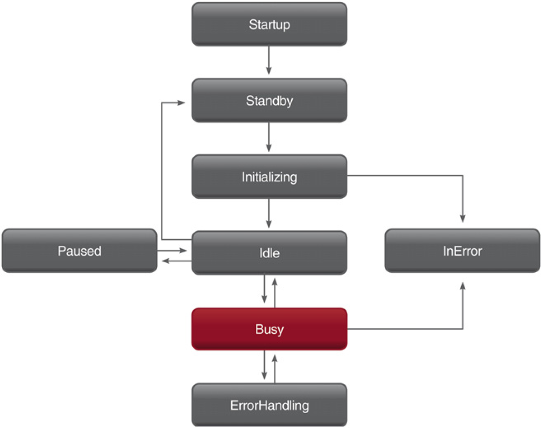
Visualization highlights the State Busy.
Figure 9 shows the control of a DeLonghi coffee machine over SiLA 1.1 (yellow cable) using the infoteam SiLA Library we presented on the Lab Automation trade show 2011.
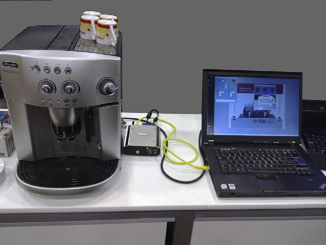
Notebook controls coffee maker via SiLA.
Outlook
The work of recent years in automation focused on the control of devices connected to a single control system. With the infoteam SiLA Library and the exponents mentioned above, the proof that the emerging standard offers a feasible network interface is provided. However, with SiLA and Ethernet, there is a high potential for applications one did not consider before SiLA. Devices can be accessed from enterprise applications, such as global device monitoring or logistics. We already started to investigate interdevice communication and distributed algorithms to improve reliability, but no results are at hand yet. These results are expected to be the subject of a future publication.
Footnotes
Acknowledgments
We thank the Tecan Group Ltd. for lending us a Tecan Sunrise Reader and F. Hoffmann-La Roche Ltd. for lending us a Thermo Scientific Multidrop. We used both devices for the MipTec trade show in 2009.