
Abstract
The scope of this project covers the storing of result data produced by generic laboratory devices during processing of analytical experiments, the data describing the examination methods, and the audit trail using the Analytical Information Markup Language (AnIML) standard. This project also considers the integration of generic devices in automated laboratory environments.
AnIML is an upcoming ASTM standard format for recording analytical data and workflows with accompanying experimental metadata. Adapting this standard to existing instruments currently requires manual intervention. The goal of this project is to automate as many steps as possible in generating an AnIML document with all its essential information supplied directly by the analytical instrument. Software with such functionality could be integrated into analytical instruments or reside in firmware boxes hooked to the instruments. This would allow a smooth transition to the new standard even in complex existing environments. A set of prerequisites have to be fulfilled before the feasibility of this approach can be shown.
The prototype application we describe here integrates the generic description of an instrument using the Laboratory Equipment Control Interface Specification, Object Management Group (LECIS OMG) Device Capability Dataset. Information about the device's commands and the device's data stream with its semantics can be found there. The experiment's metadata are provided by the test order. In both cases, XML schemas contain the information syntax. Using this information, we developed a generic interface that maps the result stream semantically and then transforms it into an AnIML document without manual intervention. At this time, we have completed and tested a prototype implementation and are working to support the full functionality of both the LECIS OMG and the ASTM AnIML standards. (JALA 2006;11:247–53)
Background
AnIML
The Analytical Information Markup Language (AnIML)1, 2 is an upcoming ASTM 3 standard for the documentation of analytical data and experiment workflows with all accompanying experimental metadata.
In addition to handling experiment-result data, AnIML is also able to manage information about different and possibly combined analytical methods (techniques), information about samples used, and workflow data. The standard supports the handling of audit trails and digital signing methods. These features support the data integrity requirements of regulatory agencies.
AnIML is an XML-based 4 markup language and consists of two logical layers. First is the AnIML Core, which is a generic data container with data elements for result data, samples, audit trails, and signatures. Second is the Technique Definition layer, which describes how the AnIML Core can be used for some particular analytical technique. A Technique Definition defines the structure of an AnIML document that corresponds to a specific analytical experiment. Implicitly, it also describes the experimental setup, the data interrelationships, data elements used, samples used, and the sample properties.
Laboratory Equipment Control Interface Specification, Object Management Group
The Laboratory Equipment Control Interface Specification, Object Management Group (LECIS OMG)5, 6 standard provides a program interface defining a set of standard methods that facilitate the smooth integration of instruments into laboratory systems and the operation of these devices. The LECIS OMG standard specifies what functionality these methods must contain and specifies the possibilities for retrieving the device status. It is the vendor's responsibility to implement these requirements. This standard has been developed to integrate devices in laboratory systems using CORBA 7 middleware; however, in this project, no middleware has been used. Detailed information about the functionality of particular methods and about the LECIS OMG standard is described in the LECIS OMG specification document. 5
The Device Capability Dataset (DCD) Schema that also belongs to the LECIS OMG specification is a machine-readable device description for a specific device. Such a description contains information about the instrument's vendor, physical characteristics of a device, description of device subunits, error codes, command macros, and other device-specific properties. With the aid of an XML file that complies with the DCD Schema it is possible to describe simple devices that contain only one subunit and have only few commands. However, it is also possible to describe a very complex instrument such as a chromatograph that has a complex command set and contains several subunits that can be processed independently.
Functional Requirements
For this demonstration project, our case study has to show how typical analytical result data produced during laboratory experiments could be recorded. For this prototype, it should be irrelevant which device acts as a data source. It must be possible to process data produced by a generic laboratory instrument. To highlight the utility of our approach across the variety of existing laboratory instruments, a balance and a nuclear magnetic resonance spectrometer (NMR) were chosen for discovery and testing purposes. However, operation with the NMR was only simulated.
The documentation of an experiment's results must contain result data, experiment description information, sample description, information about the user who carried out the experiment, and optionally an audit trail and digital signatures. The experimental result data are delivered by the instrument. Any other required information not provided by the instrument must be entered by the user, so that the documents created will conform to the AnIML standard.
Automation of an analytical experiment must not be dependent on a specific laboratory instrument. For example, it should be possible to provide weighing with nearly every available balance that can be controlled by a computer system. To resolve this requirement, the LECIS OMG specification is used. This has facilities to describe device properties and also provides a program interface for implementing device control (Fig. 1).
AnIML generator workflow overview.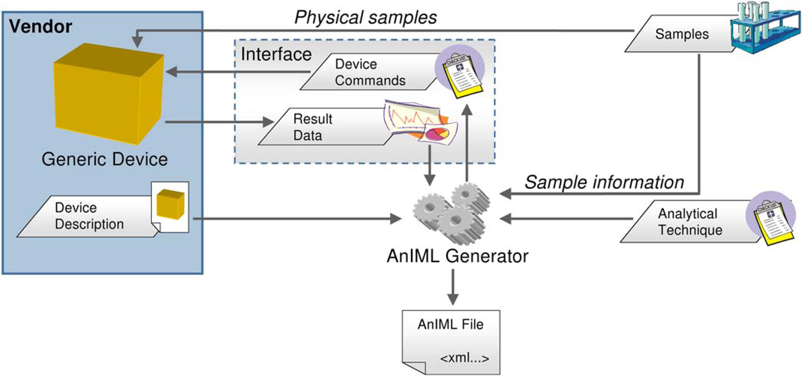
Any additional information that is mandatory for the execution of the experiment must be entered by a user before processing an experiment. This can include the following:
unambiguous sample identification;
a technique definition for the experiment describing the data structures for the AnIML document to be created;
information regarding the identification of the instrument used; and
the identity or personal information of the person performing the experiment.
Implementation
The software application is subdivided into three parts:
Device Level;
Generator Level; and
Front-end Level.
Device Level
The device level encapsulates the instrument functionality and makes the device-specific properties transparent to the software system. The components of the device level are also responsible for the device control, evaluation of instrument status, error code handling, and reading out and preprocessing the raw data stream. The instrument control design is based on a device driver and a corresponding device description. Both elements must conform to the LECIS OMG standard. A device driver must implement a uniform program interface, and the device description, created in XML, must adhere to the DCD schema.
This concept allows the device to be decoupled from the application. A DCD provided by the instrument manufacturer allows the instrument to be controlled and used in an automated system using either a generic device driver or a custom device driver developed by the manufacturer. Because a device driver must implement a unified program interface (LECIS OMG), the bonding of a device driver and the device control in the application will be instrument-independent and also uniform. A machine-readable device description (DCD) that complements a particular device driver describes the device characteristics and the result data structures and allows the integration of a new instrument into the software system without software changes. This approach provides a flexible solution and makes it easier to incorporate future changes.
The device driver encapsulates the device functionality. With the aid of a device description, the driver is able to control a generic device, to request result data, and to serve as a unified program interface for the generator level. It also represents an error domain for device-specific exceptions and error situations (Fig. 2).
AnIML generator architecture overview.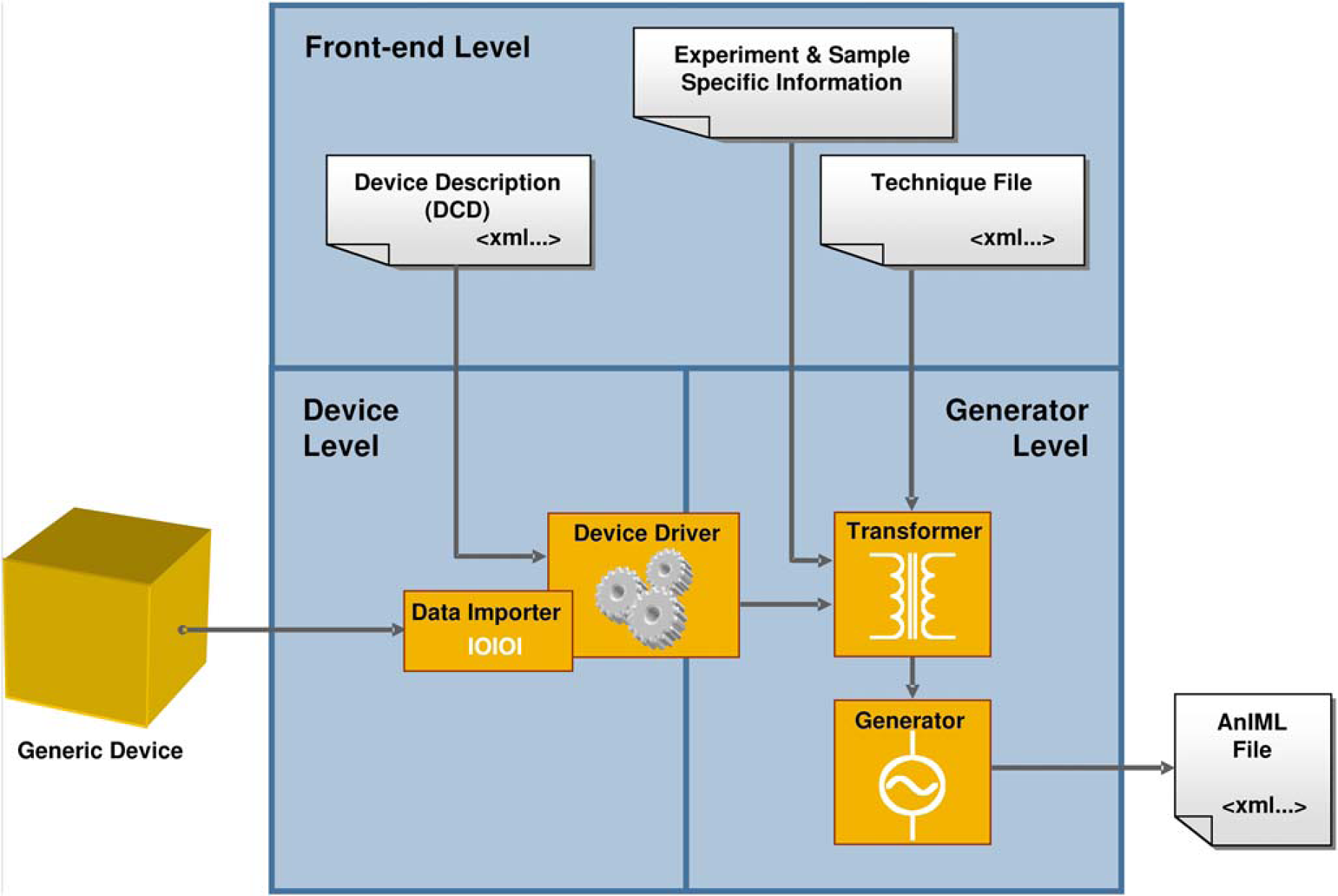
Generator Level
The generator level encapsulates the whole functionality for the generation of AnIML documents. At this level, the experiment process is coordinated, and the result data are transformed to create XML documents that are compliant to the AnIML Core Schema and a specific AnIML Technique definition.
The functionality is divided into three components: transformer, validator, and generator.
The generator is responsible for the creation of valid AnIML documents that must be compliant with the AnIML Core Schema. However, a particular AnIML document must also be conformant to the specific AnIML technique that was used for an experiment. The file with technique information for a particular experiment can be selected up front in the user interface. In addition, it is necessary to specify a device description for the instrument that was used in the experiment. The DCD can also be specified in the user interface.
To transform the experimental result data delivered by an instrument into an AnIML file, the mappings between data source (laboratory instrument) and data destination (AnIML file) must be specified. The chosen solution works by first mapping a particular data element of the specified technique definition to a command (COMMAND_TYPE) of the specified device. Second, the data elements selected in the first step must be associated with the return values (SYNC_RESPONSE_DATA) of the device command also specified in the first step. Both data-containing constructs (VectorBlue-prints 1 and SYNC_RESPONSE_DATA 5 ) provide information about the data type and units; so, it is possible to convert and to transform the values as appropriate. This data linking procedure, henceforth named “mapping”, must be performed before the experiment starts. The mapping creation functionality is located in the front-end level; in our prototype, the mappings must be created there by the user and can then be forwarded to the generator component.
It should be mentioned that our error-handling mechanism is currently not technically mature on either the device or application level and must be improved.
Front-End Level
The front-end level consists of a graphical user interface that enables importing master data, displaying master and result data, and configuring of the software application. Master data constitute the techniques for different measurements or experiments and the device descriptions in LECIS OMG format. Furthermore, there is functionality implemented to input, to administrate different experiment parameters, and to initialize an experiment workflow. The front-end level also contains the mapping facility to assign the result data elements to the corresponding data vectors in a particular AnIML document (Fig. 3).
Mapping facility.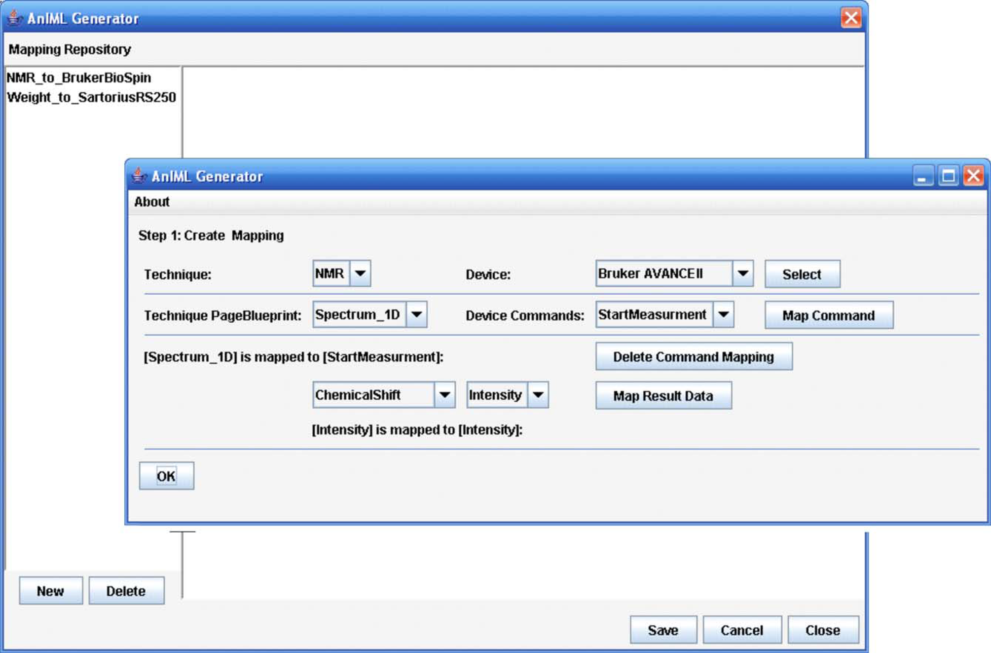
The functionality is spread over several components:
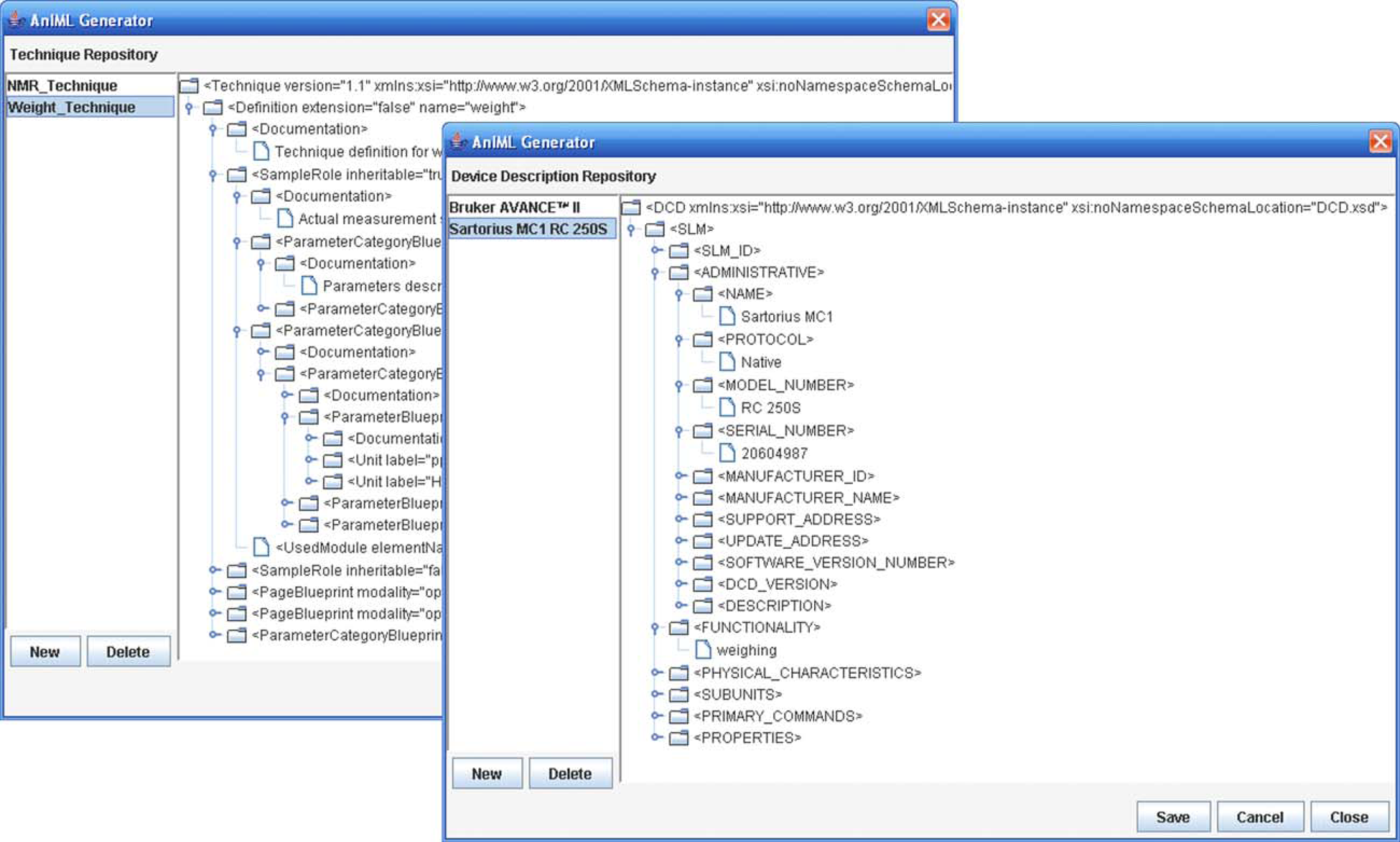
Mapping facility—creation and administration of data mappings (Fig. 3). Technique repository—importation and administration of existing techniques (Fig. 4).
Technique repository and device description repository. Device description repository—importation and administration of existing device descriptions (DCDs) (Fig. 4). Experiment panel—creation and processing of experiments (Fig. 5).
Experiment panel.
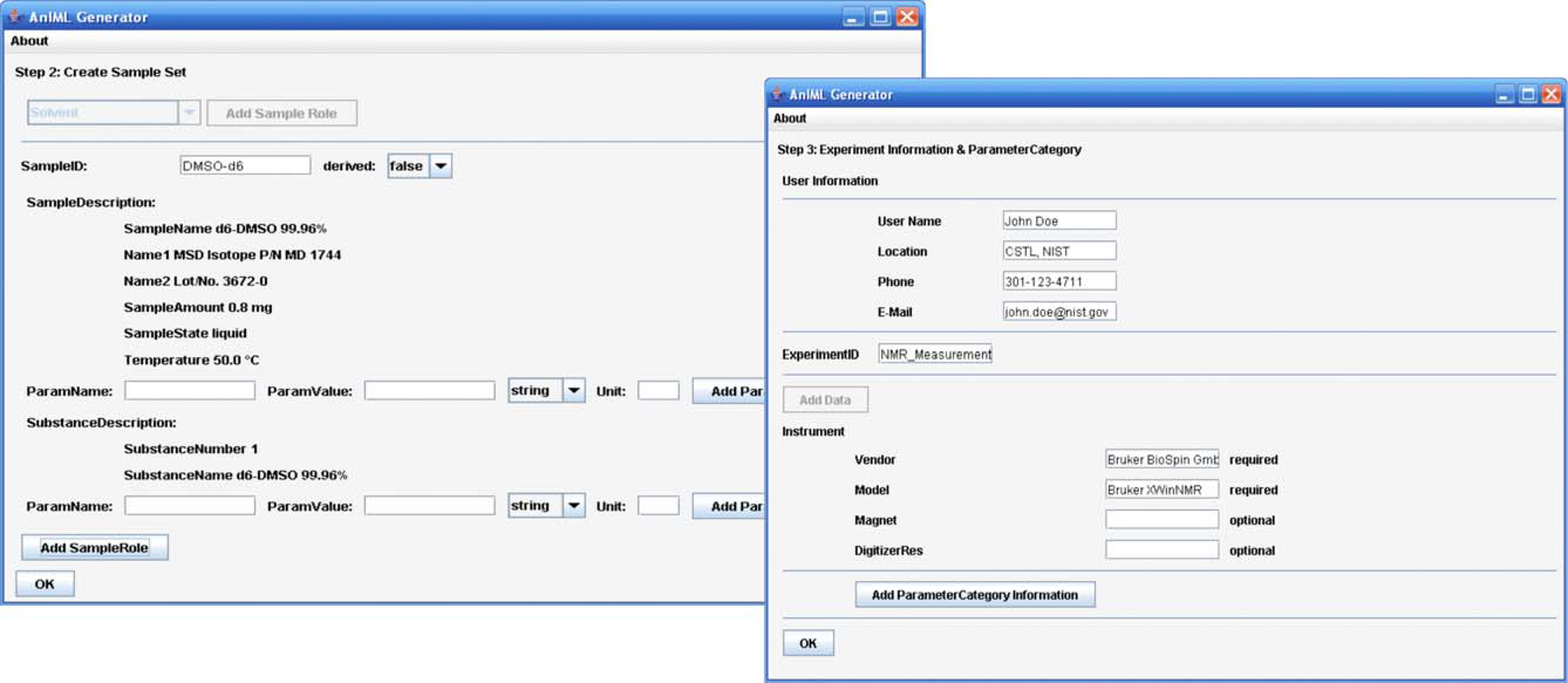
The mapping facility and an experiment panel provide the core functionality of the front-end layer. In the mapping facility, it is possible to create data maps where the result data elements of particular device commands are assigned to the data elements of an AnIML document as required by a technique. To simplify the use of the software, the data maps created can be stored for subsequent reuse.
In the experiment panel, it is possible to create an experiment and to start the processing. Creating an experiment means opening an experiment template and filling in the required experiment information, such as, the samples to be used, the experiment technique used, the instrument used, and the data maps used. Finally, the experiment can be processed, and the AnIML file is created. An AnIML viewer can display the result data (Fig. 6). The discussion of such a viewer, however, falls outside the scope of this project.
Simplified AnIML viewer.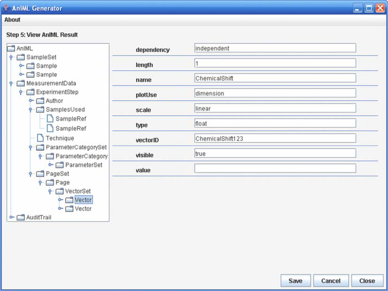
Example use case
This is an example of an experimental workflow where an analytical balance is used to provide a weighing measurement. In the first step, experiment description information must be entered by the user by selecting the desired technique definition and appropriate device description. Then, it is necessary to specify the result data container that must appear in the AnIML document and to link it to the device command, which is able to deliver the required results. The mapping process is not completed yet; the data elements of the selected AnIML data container must be linked to the return values of the desired device command. When the mapping is created, additional information such as sample information, user information, measurement and instrument parameters must also be inserted. Then the experiment can be started.
In the next step, the generator module initializes its components, the Transformer and the Device Driver, with the technique file, miscellaneous processing parameters, mappings, and a device description file. During the initialization, the transformer evaluates the specified technique file and prepares, with the help of data elements defined there, the required data structures for the AnIML document. The Device Driver is responsible for converting the abstract instructions into device-specific commands of a particular instrument and for processing the measurement. After a successful initialization, the Device Driver receives the information necessary to start the measurement. This information is created during mapping from properties in the technique definition and the DCD.
In the tested case, the balance receives the command to open the gate. The sample measured must be placed on the balance plate by the user who also must close the door using the balance's touch panel. After that the device driver gets the notification that the measurement can be performed and processes it. As soon the measurement process is finished the generator gets a notification and the result data. The data elements given in the technique definition can be transformed as defined in the available mappings, so that an AnIML document can be created. Finally, the generated document can be syntactically and semantically checked for errors. After an error-free AnIML document was created successfully, experiment documentation is available in the form of an AnIML document. It is displayed in the user interface and can be stored anywhere in the file system (Fig. 7).
Workflow example.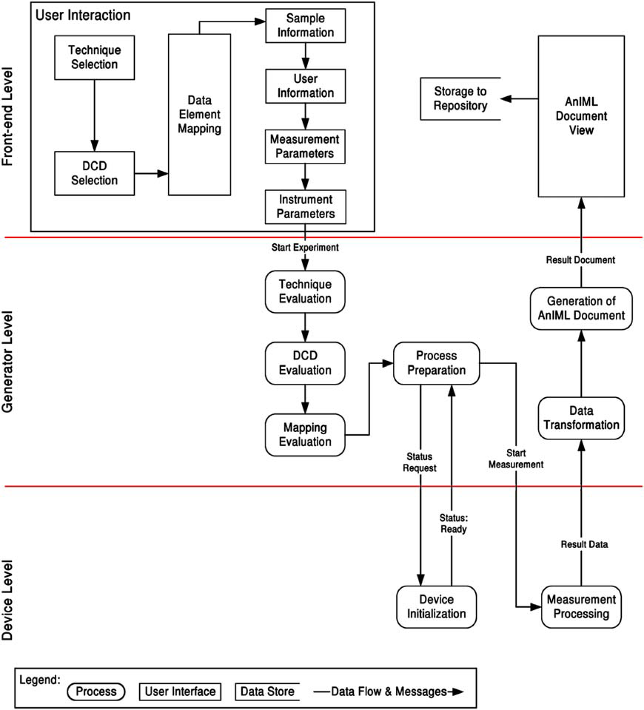
Project status
To demonstrate how our approach works, we applied it for the processing of two AnIML techniques and two particular devices. To minimize the complexity of the project, but yet to demonstrate the concepts, we chose a simple analytical balance to show how the device interfacing and control works. However, since the result data produced by a balance is trivial, we decided to use the result data from an NMR spectrometer to illustrate how the experimental output is incorporated into an AnIML document. This was done in simulation, since there was no need to repeat the device control demonstration. Since the generic mapping functionality is not yet complete, it is not yet possible to represent a full range of hierarchies. The mapping construct must be extended and optimized. Much of the information that currently must be entered manually in the front-end may in the future be fed from a LIMS or other secondary processes to minimize user interaction at this application level.
Our prototype of the AnIML generator successfully shows the implementation and combination of the XML-based standards, AnIML and LECIS OMG. This project demonstrates how our basic concepts can be used to implement software that is capable of generating standardized experiment-result documentation for analytical experiments processed by nonspecific laboratory instruments. When implemented on a broader scale, this approach using standardized instrument control through LECIS OMG coupled with a standardized way of handling result data and metadata can go a long way toward eliminating the difficulties in creating and developing automated analytical chemistry systems.